Adura Technologies SDR10PA Wireless Lighting Control for commerical and industrial buildings User Manual Sensor Interface Manual Myraid Pro 01
Adura Technologies, Inc. Wireless Lighting Control for commerical and industrial buildings Sensor Interface Manual Myraid Pro 01
Contents
- 1. User Manual
- 2. User Manual Antenna Instructions
User Manual
SI Instructions 07.09
w w w . a d u r a t e c h . c o m
This equipment has been tested and found to comply with the limits for a Class A digital device, pursuant to Part 15 of the
FCC Rules. These limits are designed to provide reasonable protection against harmful Interference when the equipment
is operated in a commercial environment. The equipment generates, uses and can radiate radio frequency energy and, if
not installed and used in accordance with the instruction manual, may cause harmful interference to radio communica-
tions. Operation of the equipment in a residential area is likely to cause harmful interference in which case the user will be
required to correct the interference at his/her own expense.
Class A Digital Devices
CAUTION
• Disconnect all power before installation or service.
• All installation and maintenance work must be performed by qualified personnel.
• The Sensor Interface must be installed in accordance with state, local and national
electrical codes and requirements.
INSTALLATION
INSTRUCTION MANUAL
WARRANTY INFORMATION
Adura Technologies
™
warranties its products to be free of defects for a period of five years. Adura Technologies will, at its option,
repair or replace any product that is defective in materials or manufacture that is returned to ADURA within the warranty period.
This warranty is void if this product has been installed improperly or in an improper environment, overloaded, misused, or altered
in any manner, or not installed in accordance with any labels or instructions. Adura Technologies is not liable for incidental, indirect,
special, or consequential damages, including without limitation, damage to, or loss of use of property, revenue or profit. This
warranty does not cover the cost of installation, removal or reinstallation.
To comply with RF exposure compliance requirements, for mobile configurations, a separation distance of at least 20 cm must be
maintained between the antenna of this device and all persons. This device must not be co-located or operating in conjunction with
any other antenna or transmitter.
Installation Materials (Not Supplied)
Wiring connectors. All existing wiring connectors must be replaced with new UL listed
wiring connectors, either wire nuts or captive-type connectors. All wiring connectors must
be correctly sized for the application, the number and the size of the electrical conductors.
sensor interface
The Sensor Interface is to be used in lighting systems to control lighting in commercial and
industrial buildings. It transmits signals received from an occupancy sensor and from a
photocell onto ADURA’s™ wireless network.
The Sensor Interface is intended to be used in a network of devices which communicate
wirelessly, such as Light Controllers, wall control devices and software management tools.
The Sensor Interface is intended to mount onto an electrical junction box. Often, the
Sensor Interface and the junction box will be mounted in the space above a finished
ceiling. The Sensor Interface is intended for indoor use only. It is rated for mounting in
a plenum.
The Sensor Interface is a low voltage device that must be powered by a Class 2 power
supply.
The Sensor Interface has 2 input channels:
• Channel 1 = Blue Wire
• Channel 2 = Yellow Wire
Either channel can be used to monitor standard low voltage occupancy sensors, low
voltage photocells and dry contracts.
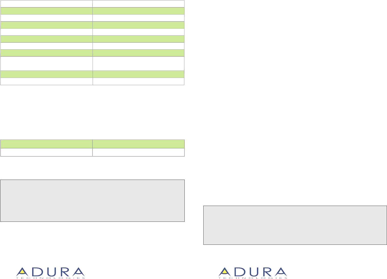
Specications:
Input Voltage:
Power Consumption:
Radio Frequency:
RF Transmission Output Power (Average):
15 – 30 VDC
11 mA
2.4 GHz
+12 dBm
40 to 120 deg F, dry location
Dimensions:
Operating Environment:
Sensor Input Channels (2):
Configuration Programming: Configuration programming
stored in non-volatile memory
Mounting:
UL Listing: UL 2043 plenum rated
0 - 30 VDC
Wires: 9" 600 VAC plenum rated, 18 AWG solid conductors
3 1/4” L x 1 7/16“ W x 1” H
Ordering Information:
Catalog Number Description
Sensor Interface - 2 Input ChannelsSI - 2C
Snaps into 1/2” knockout on electrical box
ADURA TECHNOLOGIES™
San Francisco, CA 94105
Tel: 415.227.0868 • Toll Free 1-888-828-8281
ADURA TECHNOLOGIES™
San Francisco, CA 94105
Tel: 415.227.0868 • Toll Free 1-888-828-8281
TM TM
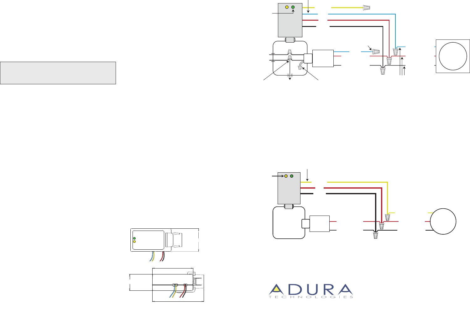
Wiring Diagram #1
OCCUPANCY SENSOR WIRING
Wiring Diagram #2
PHOTOCELL WIRING
Class 2 Power
Supply
RED (+24 VDC)
BLACK (Return)
(0-10 VDC Signal)
Line Voltage
Connections
BLACK
RED
YELLOW
Junction
Box
Photocell
Power
Pack
Sensor
Interface
Installation Instructions:
The Sensor Interface is designed to be inserted
into a knockout on an electrical junction box.
All Sensor Interface wiring is low voltage.
1. Locate the junction box on which the power
pack is mounted. (See occupancy sensor
and/or photocell section for more information).
This is likely to be the preferred location for
mounting the Sensor Interface.
2. Locate a spare 1/2” knockout on the junction
box. Remove the knockout and slide the
Sensor Interface into the opening until it
catches.
3. With a volt meter, identify the +24 VDC and
Return wires from the power pack.
4. Connect the +24 VDC and Return wires from the
power pack to the Sensor Interface, as shown in
the wiring diagrams.
New Occupancy Sensor:
If new occupancy sensors are required, purchase
any standard low voltage occupancy sensor and
associated power pack. Install the occupancy
sensor and power pack according to the
manufacturer’s instructions.
(Do not connect the occupancy sensor signal to
the power pack. Do not connect the line voltage
wiring to the relay on the power pack).
Existing Occupancy Sensors:
Locate any existing low voltage occupancy
sensor and its associated power packs.
Wiring an Occupancy Sensor:
1. Verify that the occupancy sensor detects
and signals occupancy as intended.
(+24 VDC on occupancy sensor signal wire
when occupied).
2. Connect the signal wire from the occupancy
sensor an available Sensor Interface channel
wire. For existing occupancy sensors,
disconnect and secure the signal wire on the
power pack.
Channel 1 = Blue Wire
Channel 2 = Yellow Wire
3. For existing occupancy sensors, disconnect the
line voltage wiring from the power pack relay.
Connect the lighting load wiring to the hot
wire. Secure the relay leads with a wire nut.
Wiring a Photocell:
1. Install and wire a standard 0-10 VDC photocell
and power pack or other Class 2 power supply
per the manufacturer’s instructions.
2. Connect the signal (wire or terminal) on the
photocell an available Sensor Interface channel
wire.
Channel 1 = Blue Wire
Channel 2 = Yellow Wire
Auto Detection:
The Sensor Interface detects what type of sensor
is connected to each channel prior to being
commissioned.
Verifying Installation:
The two LEDs are used to verify the status of the
field wiring. Each channel has an LED.
Channel 1 = Green LED
Channel 2 = Yellow LED
If a channel has never been used, then its LED will
blink every two seconds. If an occupancy sensor is
connected and occupancy is signaled, then the
LED for that channel will be solid on. If a
photocell is connected, then the LED for that
channel will blink. As the light level increases, the
speed of the blinking will increase.
Programming:
Refer to the setup application instruction for
information on programming the Sensor
Interface.
YELLOW LED
Channel 2 Signal
ADURA TECHNOLOGIES™
San Francisco, CA 94105
Tel: 415.227.0868 • Toll Free 1-888-828-8281
Sensor
Interface
DO NOT CONNECT THE SENSOR INTERFACE IF THE
SUPPLIED VOLTAGE IS GREATER THAN 30 VDC.
STOP AND IDENTIFY ANOTHER POWER SOURCE.
TM
BLACK (Return)
RED (+24 VDC)
1
1/2”
2
1/2”
1”
3
1/4”
Dimensions:
YELLOW
RED (+24 VDC)
BLACK (Return)
Power
Pack
Class 2 Power
Supply
To Lighting
Load
Disconnect and
secure relay leads
Disconnect
lighting load from
power pack relay
and connect lighting
load to hot wire
BLUE
DISCONNECT
AND CAP
EXISTING WIRE
Junc tion B ox
Sensor
Interface
N
H
Typical wire colors. Verify actual wire
colors with installed occupancy sensor.
Channel 1 Signal
Occupancy
Sensor
GREEN LED
RED (+24 VDC)
BLACK (Return)
BLUE (Signal)
BLACK
RED
BLUE