Advance Multimedia Internet Technology CDD531AMU02 WIFI ADSL2/2+ROUTER2 User Manual
Advance Multimedia Internet Technology Inc. WIFI ADSL2/2+ROUTER2
UserManual.wiki
>
Advance Multimedia Internet Technology
>
CDD531AMU02 User Manual
>
Users Manual 1
Contents
1.
Users Manual 1
2.
Users Manual 2
Users Manual 1
Navigation menu
Upload a User Manual
Namespaces
Wiki Guide
HTML
PDF
Info
Views
User Manual
Discussion / Help
Navigation
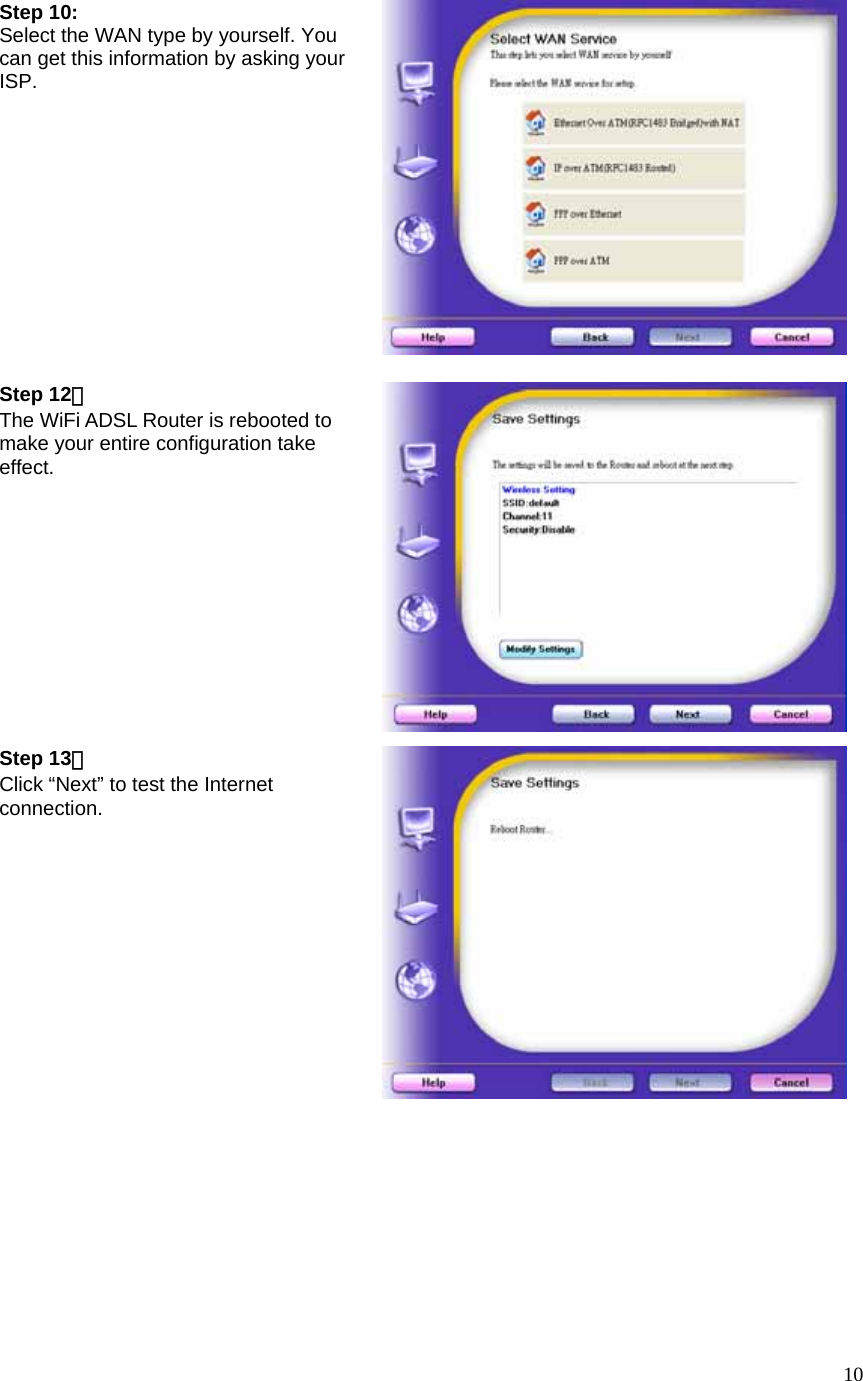
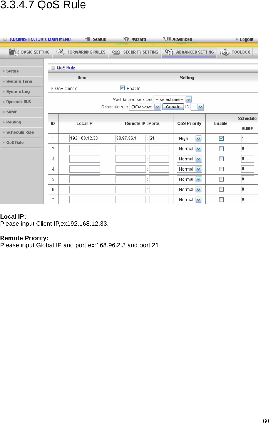
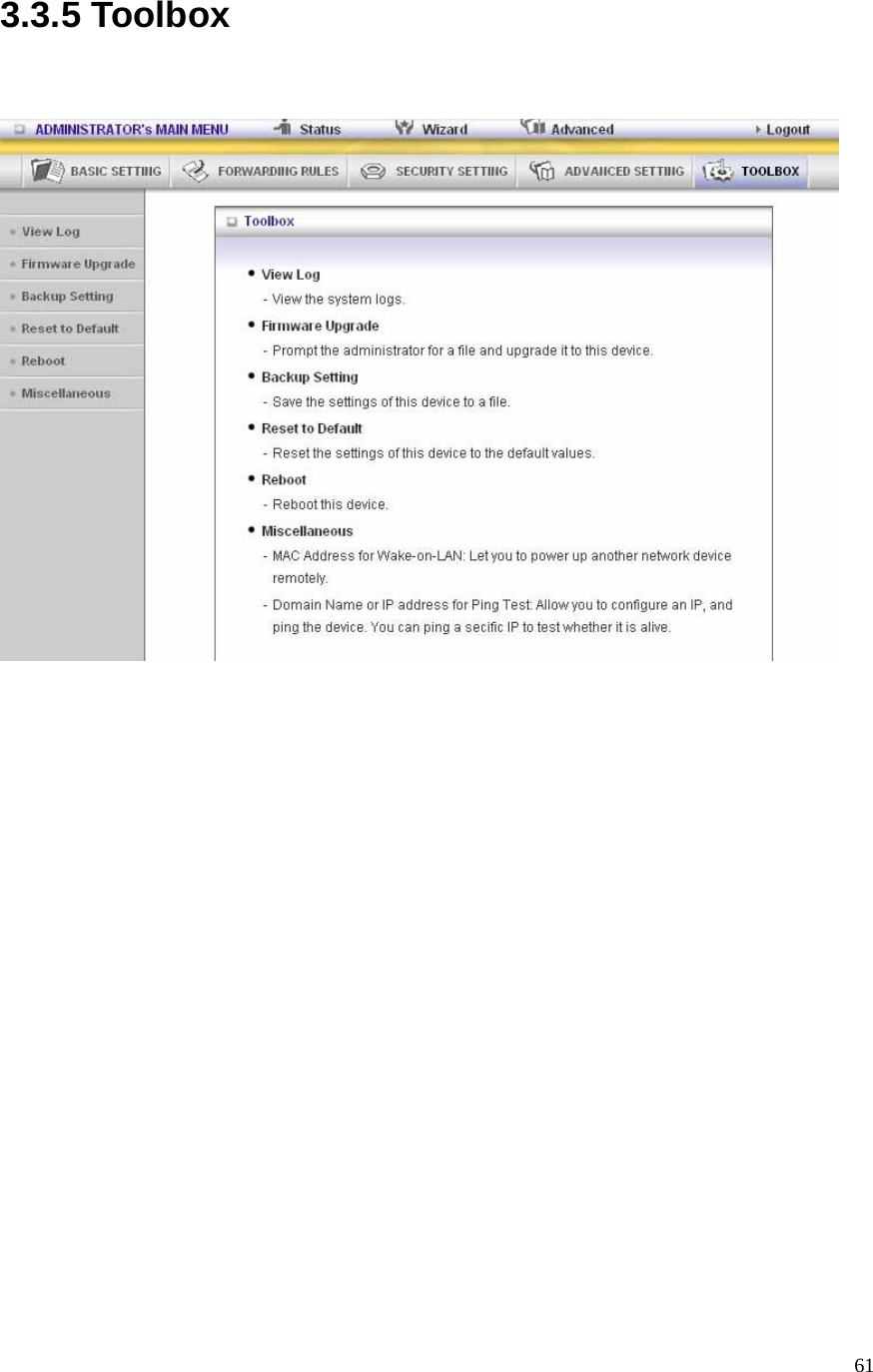
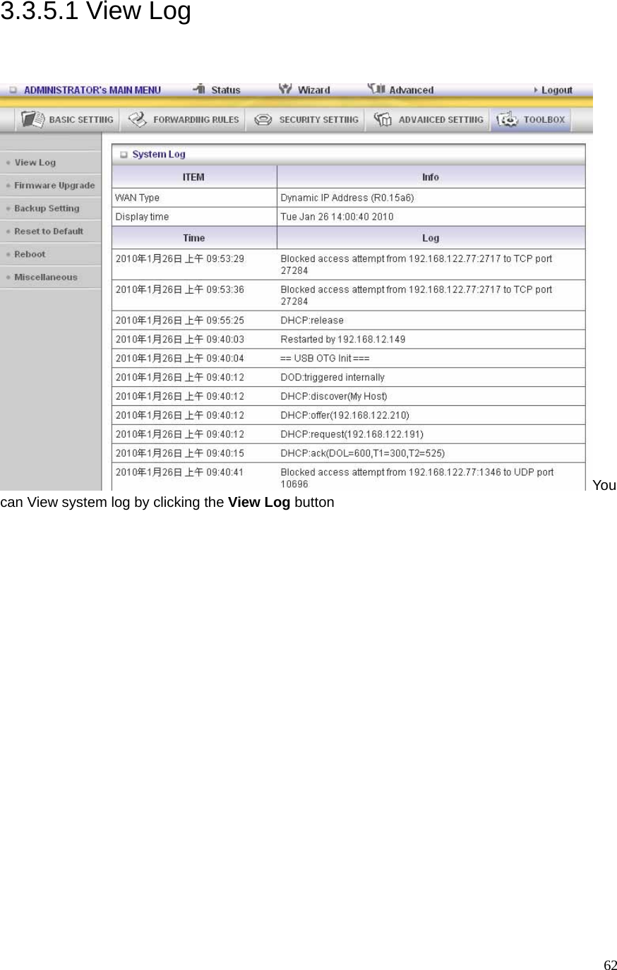
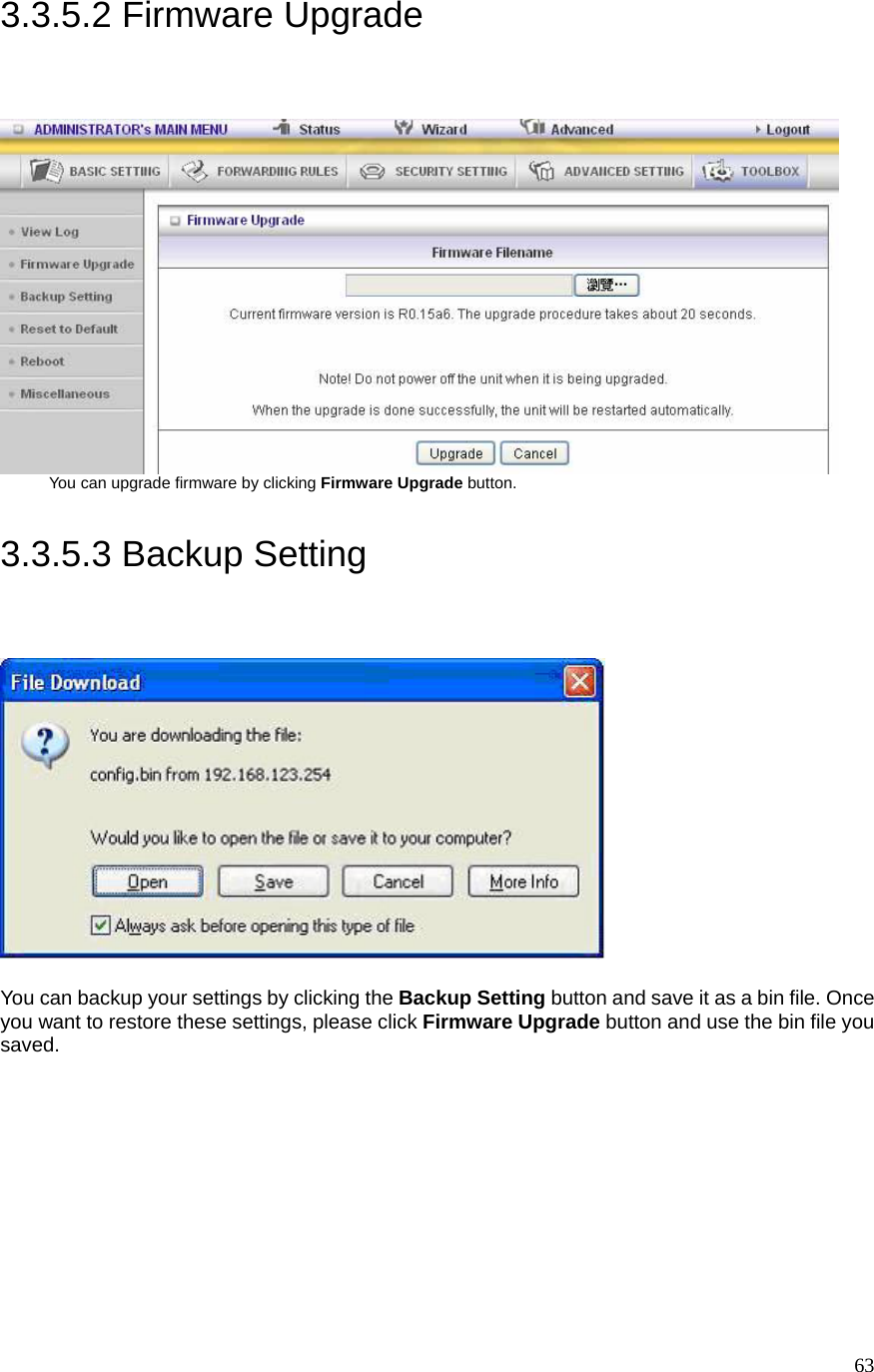
![9Step 7: Configure your wireless interface. Step 8: Insert SSID, Channel and Security options, and then click “Next” to continue. Step 9: Auto detect the WAN service, just click the [Next] button. Or you could select the WAN type by yourself via select the check box [Let me select WAN service by myself] Æ jump to Step 10.](https://usermanual.wiki/Advance-Multimedia-Internet-Technology/CDD531AMU02.Users-Manual-1/User-Guide-1598927-Page-9.png)