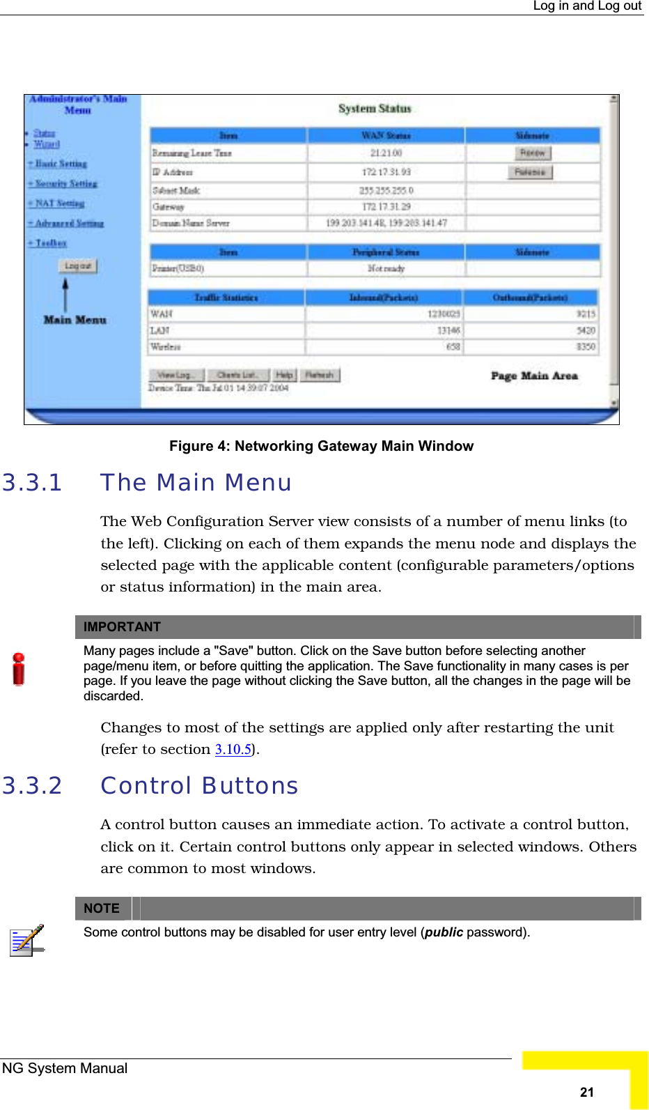
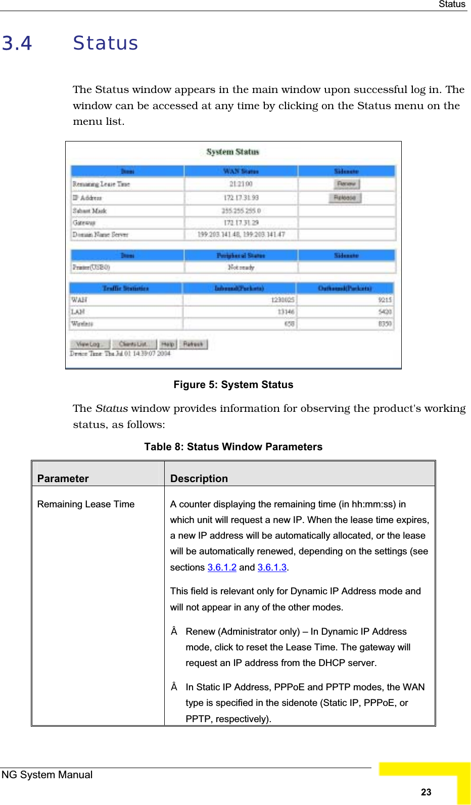
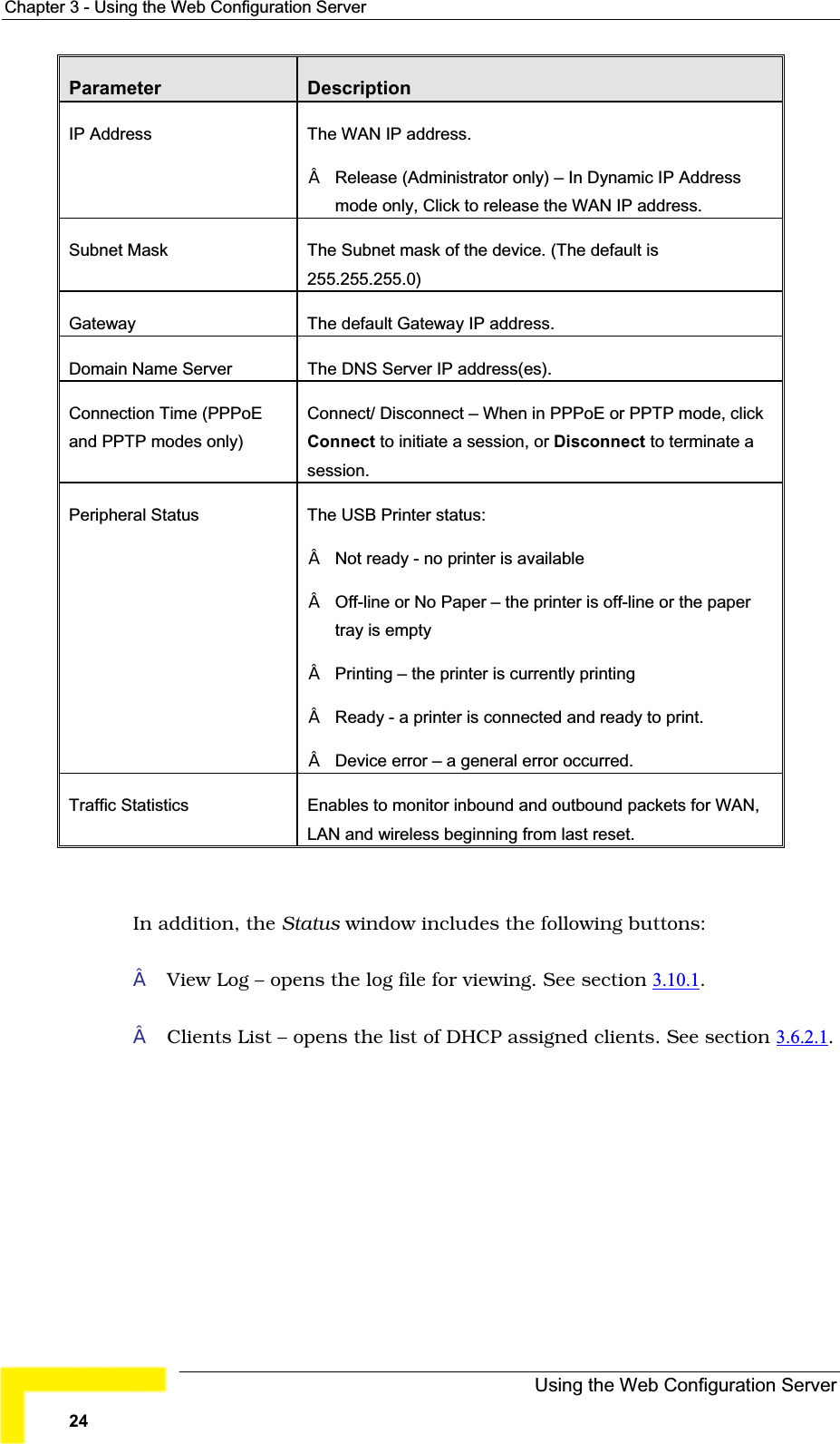
Advance Multimedia Internet Technology TE1088 Networking Gateway User Manual TE1088 Manual 971106
Advance Multimedia Internet Technology Inc. Networking Gateway TE1088 Manual 971106
UserManual.wiki
>
Advance Multimedia Internet Technology
>
TE1088 User Manual
User manual
Navigation menu
Upload a User Manual
Namespaces
Wiki Guide
HTML
PDF
Info
Views
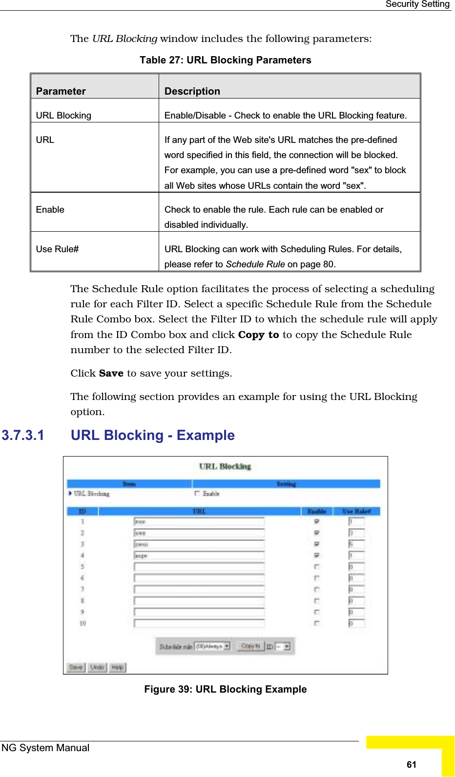
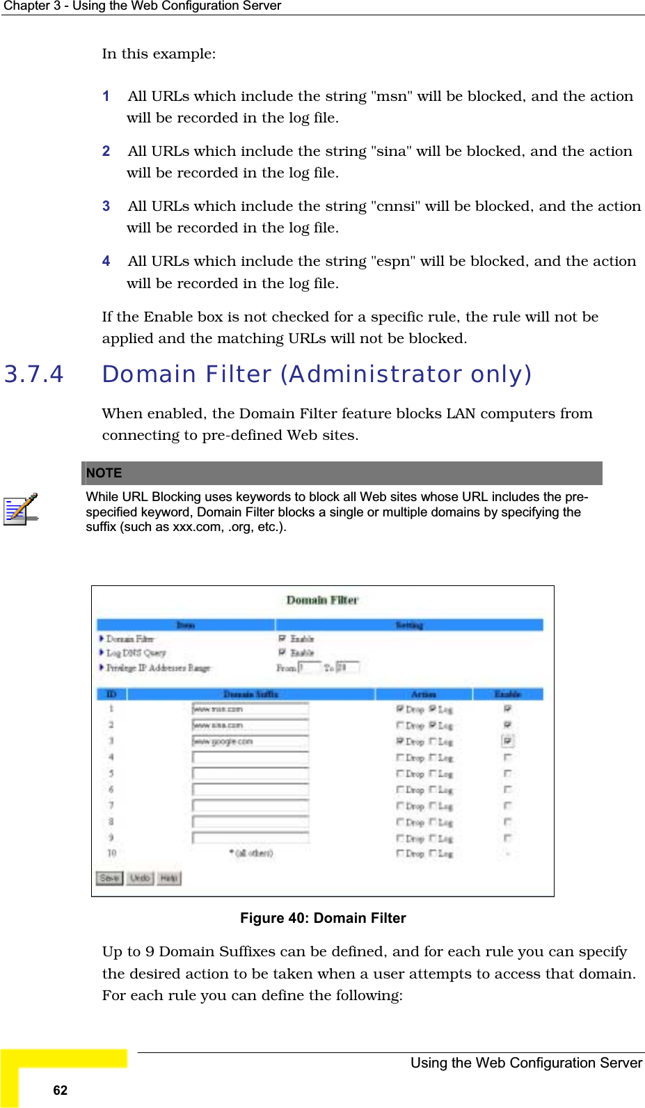
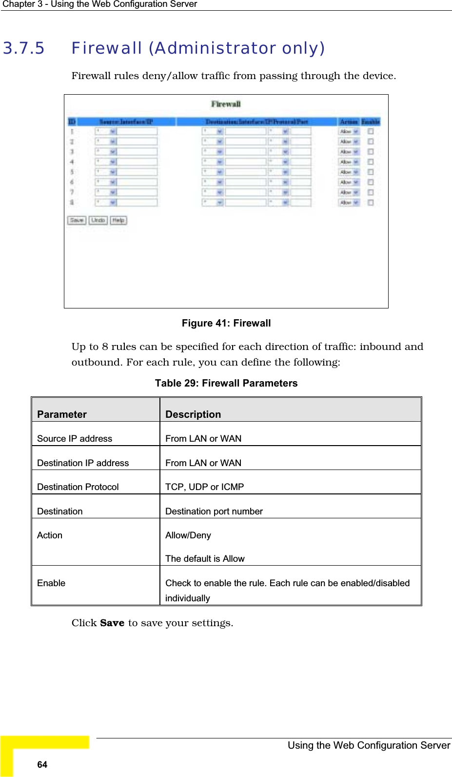
User Manual
Discussion / Help
Navigation