Advance Multimedia Internet Technology WL561CAM CardBus Adapter User Manual CardBus
Advance Multimedia Internet Technology Inc. CardBus Adapter CardBus
UserManual.wiki
>
Advance Multimedia Internet Technology
>
WL561CAM User Manual
Users Manual
Navigation menu
Upload a User Manual
Namespaces
Wiki Guide
HTML
PDF
Info
Views
User Manual
Discussion / Help
Navigation

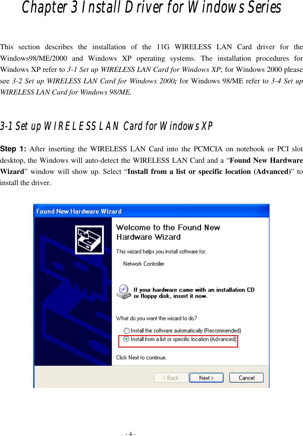
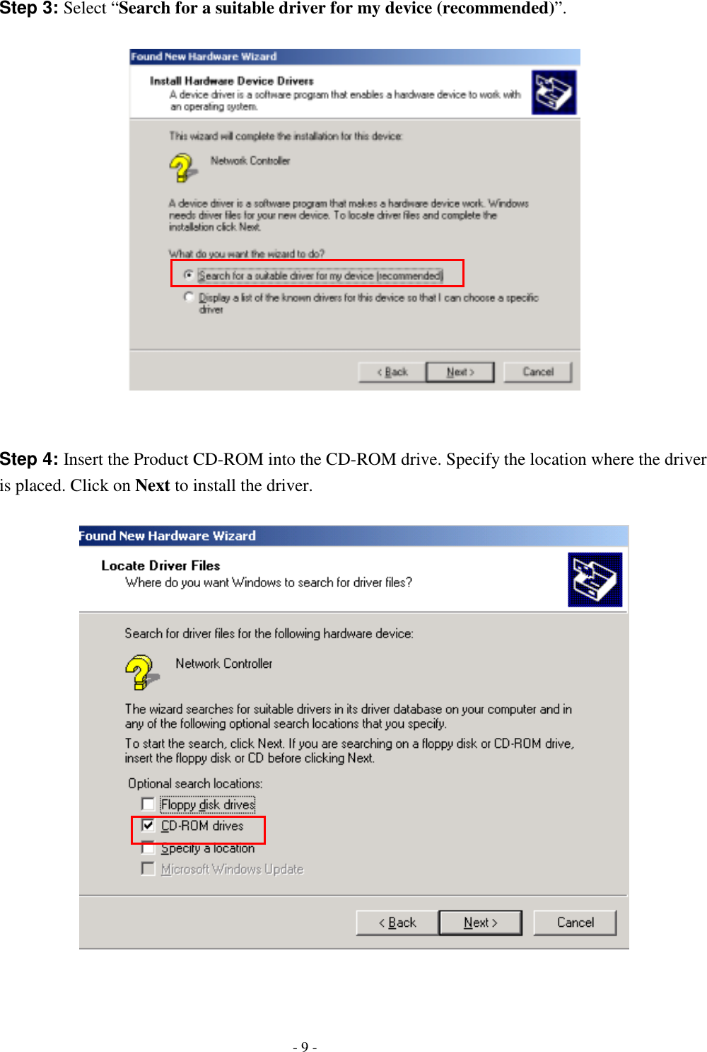
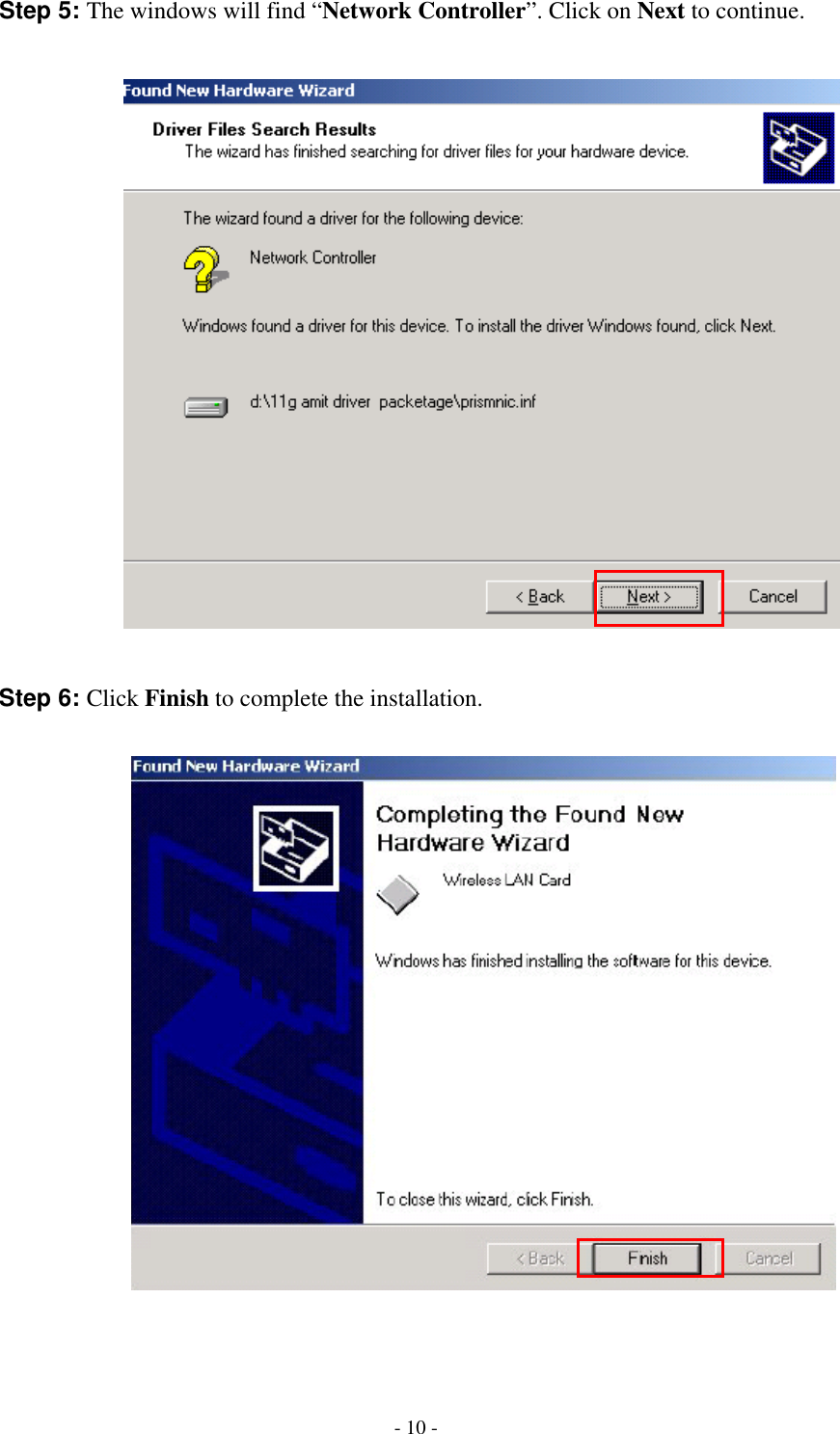
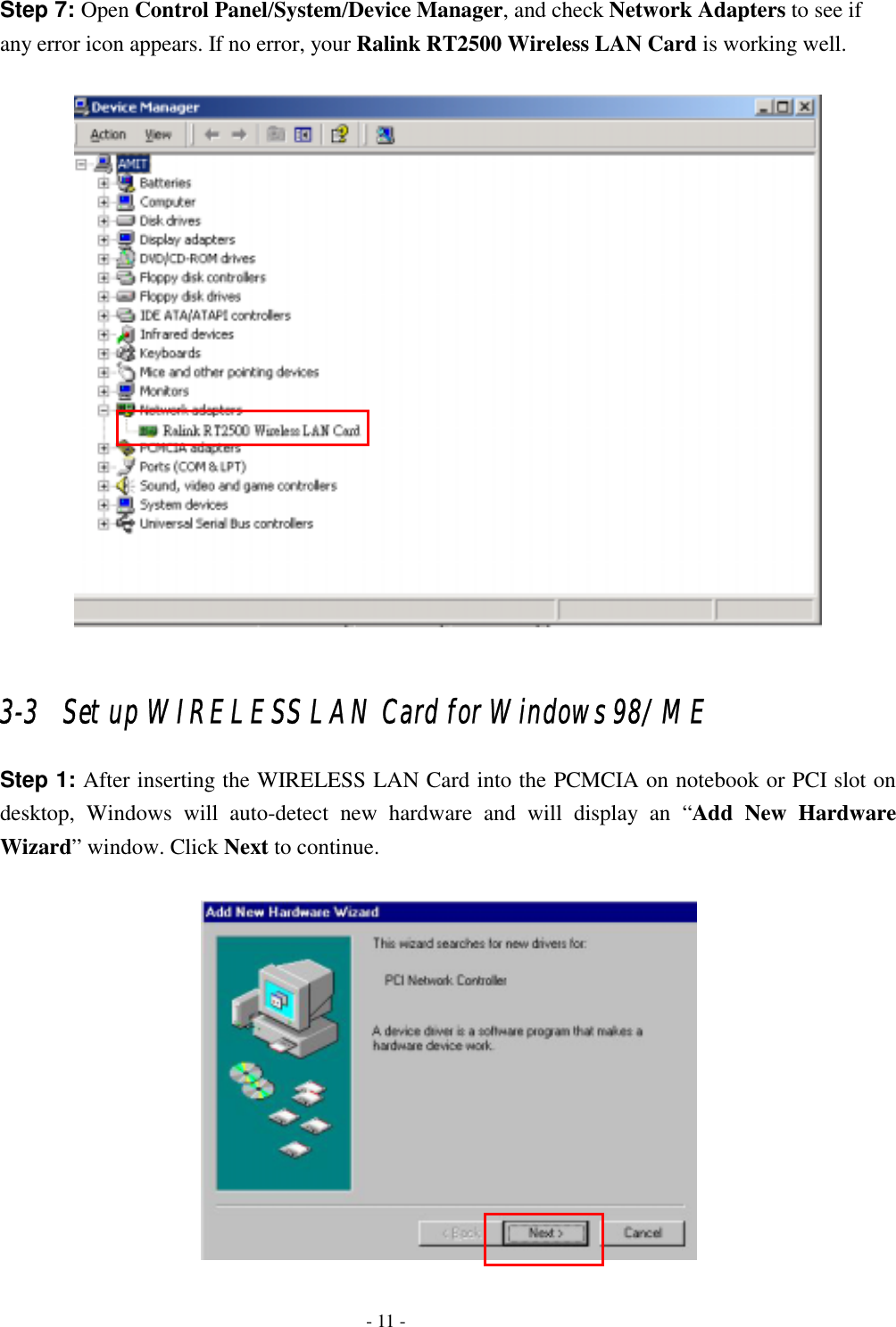
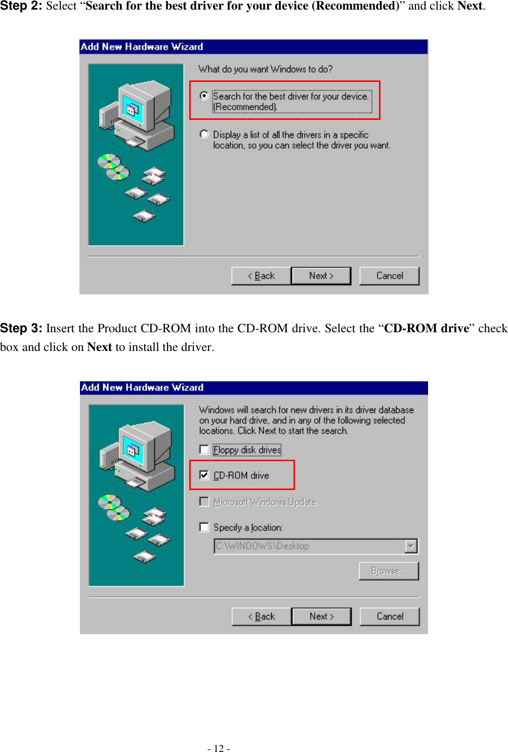
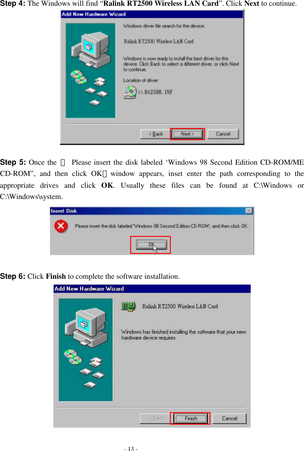
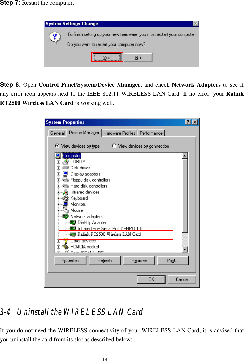
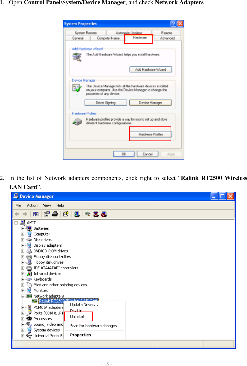
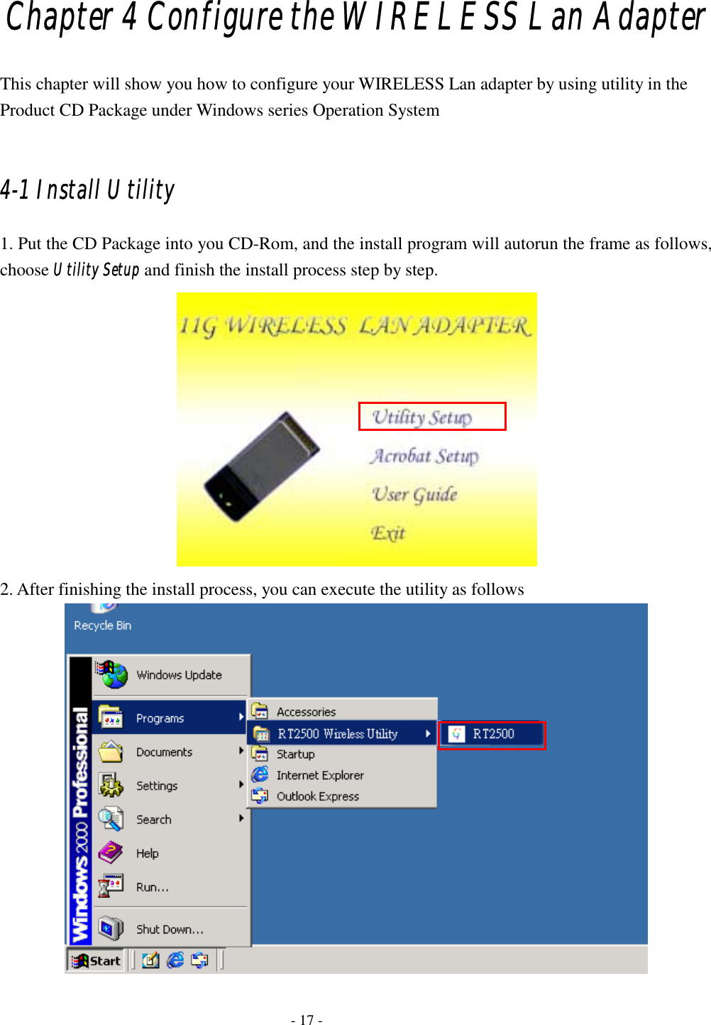
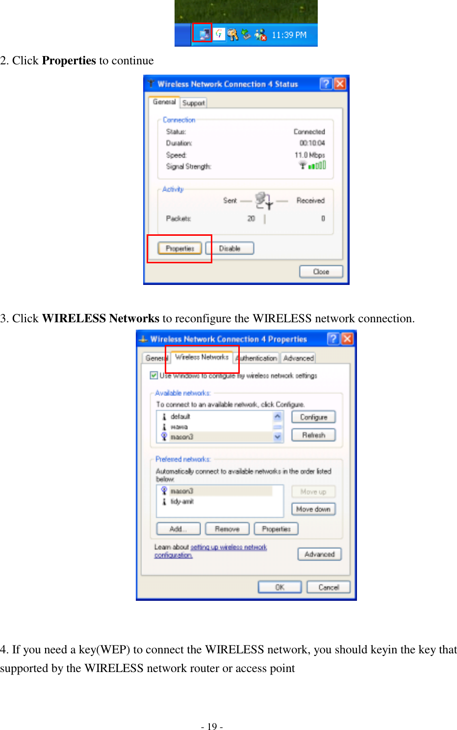
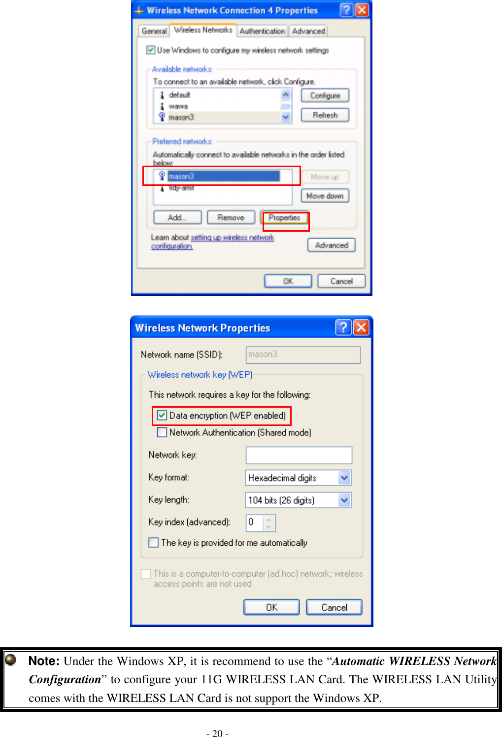
![Step 2: Insert the Product CD-ROM into the CD-ROM drive. Select “Search removable media [floppy, CD-ROM…]” check box and click on Next to install the driver. Step 3: The windows will find “Ralink RT2500 Wireless LAN Card” and start copying corresponding files into the system. Click on Next to continue. - 5 -](https://usermanual.wiki/Advance-Multimedia-Internet-Technology/WL561CAM/User-Guide-597382-Page-9.png)