Advance Security R40 Car Alarm Receiver User Manual FAX
Advance Security Inc Car Alarm Receiver FAX
User Manual

CE400
Transmitter Operation and Programming
• Programming transmitter
This receiver/Module can program up to 4 different transmitters for each channel output
Enter:
1. Use a small screwdriver to press the programming switch until the LED start to flash (about 2 seconds) the release
2. Within 10 seconds press any transmitter button and hold it until the LED solid on (The transmitter programmed), then
release the button.
3. Wait until the LED flashing again.
4. To program second ~ fourth transmitters, wait got LED flashing again and repeat steps 2 ~ 3.
Exit:
1. Press the program switch 1 times again. (Blue LED turn-off)
2. Or, leave it for about 10 seconds, it will automatically exit.
Note:
If more than 4 transmitter’s codes programmed, the system only keeps the very last 4 codes. The previous codes will void
automatically. (eg. You already programmed 4 codes into the system. You may program additional codes No. 5 and 6 into the
system, the codes No. 1 and 2 will be void while codes No 3 ~ 6 stays.
• Programming timer output:
This receiver/module can select 6 different timer output modes
Enter:
1. Use a small screwdriver to press the programming switch and hold it until the LED starts flashing slow (about 2 second),
then release
2. Then press programming switch 3-times again
3. The LED will start to flash, and the timer output programming mode status (see below chart)
4. Push the transmitter button (The one you just programmed) to select desirable output timer mode.
5. If LED with 1 flash … pause (0.5-second mode). To select the next mode press the button one time to change to the next
timing output, that is 1.0-second mode.
6. If LED with 5 flashes … pause (Momentary mode), to select 1-second mode, press the button 3 times.
Output Timer Mode LED Status
0.5 second timer output 1 flash ... pause
1 second timer output 2 flash ... pause
2 second timer output 3 flash ... pause
3 second timer output 4 flash ... pause
Momentary pulse output 5 flashes ... pause
Latch output 6 flashes ... pause
Note:
In each mode the LED will flash 5 times, (eg. In latch mode, LED will flash, "6 flashes ... pause" for 5 times.) Allowing you to
check the current mode status. If there is no transmitter button pressed over the 9 times flashing, the system would
automatically exit the programming timer output.
Exit:
1. Press the program switch again. (LED off)
2. Or, leave the LED to flash for 5 times, it will automatically exit.
CE400
The above 4 channel are individual. The methods of Programming transmitter and Programming
timer output are the same
• Relay Output
1. Unit has 4-output (4-channels) by relay that has N/C, COM, and N/O
2. The relays are 10Amp
3. Each channel output can programmable independently
• The Color wire of Output
Channel 1: N/C --- Blue/Red COM --- Blue N/O --- Blue/White
Channel 2: N/C --- Green/Red COM --- Green N/O --- Green/White
Channel 3: N/C --- Purple/Red COM --- Purple N/O --- Purple/White
Channel 4: N/C --- Black/Red COM --- Black N/O --- Black/White
This receiver/Module is design to remote control a garage door, trunk release motor, window roll up/down
module & other electronic equipment (included home security)
• Instruction Idea
Ex. Channel 1
These wires are connected to the terminals of the on-board Channel 1 Relay. When the control module receivers the code
programmed into Channel 1, this relay activated.
Blue Wire: Relay common, terminal #30.
Blue/White Wire: Relay normally open, terminal #87.
Blue/Red Wire: Relay normally close, terminal #87A
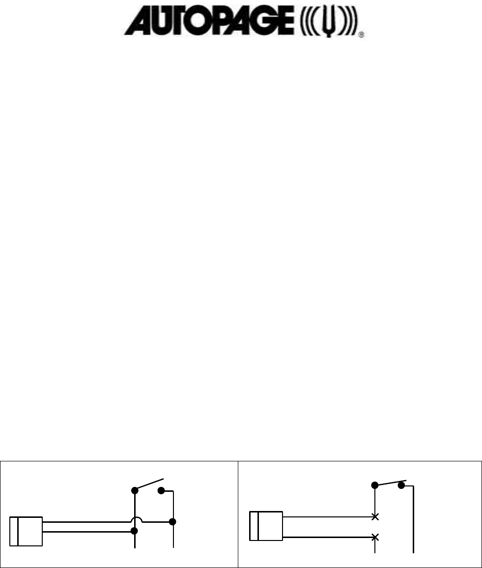
To interface with a garage door opener, first determine if the garage door opener’s wall awitch connects (normally open switch
type), or disconnects the wires (normally closed switch type). Most garage door openers use a normally closed switch. Once
the switch type has been determined, interface with the module as shown in the following diagrams.
Blue/White Wire #30
Blue Wire #87
NORMALLY OPEN SWITCH
To Garage Door Opener
Blue Wire #30
Blue/Red Wire #87A
NORMALLY CLOSED SWITCH
To Garage Door Opener
CUT
This device complies with part 15 of the FCC rules. Operation is subject to the following two conditions.
(1)This device may not cause harmful interference, and
(2)This device must accept any interference received, including interference that may cause undesired operation.
Per FCC 15.21, you are cautioned that changes or modifications not expressly approved by the part responsible for
compliance could void the user’s authority to operate the equipment.