Advance Security TR05 Car Alarm Transceiver User Manual RST871A OP 3KEY
Advance Security Inc Car Alarm Transceiver RST871A OP 3KEY
UserManual.wiki
>
Advance Security
>
TR05 User Manual
User Manual
Navigation menu
Upload a User Manual
Namespaces
Wiki Guide
HTML
PDF
Info
Views
User Manual
Discussion / Help
Navigation
![OCT/11/2002 RST871A OP 6disarm your security system, No chirp sound will be heard, arm / disarm confirmation will be through the vehicles parking lights only. SHOCK SENSOR BY-PASS: Press the button on the transmitter two times within 3 seconds will arm the security system and by-pass the shock sensor. The system will chirp one additional time to confirm the sensor bypass mode was activated. The sensor bypass feature is programmed to activate for one arming cycle only. The security system will return to normal operation during the next arming cycle. H. PASSIVE ARMING Active arming / disarming is controlling your security system via the remote transmitter. This security system is equipped with an optional Passive Arming feature, which allows the security system to arm 30 seconds after the last door is closed. Operation is as follows. 1. Turn the ignition to the “OFF” position and exit the vehicle. 2. After all entrances are closed, the security system LED will flash fast for 30 seconds. If you reopen any door / hood / trunk, the security system LED will stop flashing. It will begin flashing again once the vehicle all entrances are closed. 3. After 30-second timer has elapsed, the security system will automatically “ARM”. The siren will chirp [1] time and the parking lights will flash [1] time. PASSIVE ARMING WITH PASSIVE DOOR LOCKING (See Alarm Feature “I - 2” Programming): The vehicle doors will automatically lock after passive arming cycle has been completed. PASSIVE ARMING BY-PASS: While the system disarmed, Press the buttons twice, the security will respond with [1] chirp and LED will turn “ON”. The security system will remain in this temporally state for as long as you wish. To exit passive by-pass, press the transmitter or button and the system will return to normal status. I. ACTIVE DISARMING – UNLOCK & DISARM: 1. Press button on the transmitter. 2. The siren will chirp twice and parking light flash twice to indicating that the security system is now disarmed. The vehicle’s door will unlock and dome light turns on for 30 seconds upon disarming when interfaced with the security system. System Disarm Doors Trigger Trunk/Hood Trigger Warn away Trigger Shock Sensor Trigger Ignition Trigger Clear The Flash Icon: Press the button 3 times within 3 seconds will clear the flash icon on the LCD screen transmitter. TAMPER DISARMING: If alarm triggered, upon disarm the system, siren chirp 4 times, parking light flash 3 times. PATHWAY ILLUMINATION (See Alarm Feature “II - 3” Programming): This feature turns the parking light “ON” for 30 seconds upon a unlock signal and for 10 seconds upon the lock signal. TWO STEPS DOOR UNLOCK (See Alarm Feature “III - 2” Programming): This feature will independently unlock the driver’s door only when disarming the security system. Pushing the button a second time within 3 seconds will unlock the other doors.](https://usermanual.wiki/Advance-Security/TR05/User-Guide-283064-Page-6.png)
![OCT/11/2002 RST871A OP 7AUTOMATIC RE-ARM (See Alarm Feature “I - 3” Programming): If this feature is selected, the security system will automatically re-arm itself in 60 seconds after disarming with remote transmitter. Automatic rearm will cancel if any door is opened before the 60 seconds timer has elapsed. J. DISARMING WITHOUT A TRANSMITTER ( Alarm Feature III - 1 Programming ) OVERRIDES THE ALARM WITHOUT PASSWORD PIN CODE: (Factory Default Setting) The Override function may be used if the remote transmitter is lost or inoperative. 1. Enter the vehicle and turn the ignition switch to 'ON’ position. (Alarm will sound.) 2. Within 10 seconds push and release the valet switch The alarm will stop sounding and enter the disarm mode. You can now start and operate the vehicle normally. OVERRIDE THE ALARM WITH PASSWORD PIN CODE: (Alarm Feature III - 1 Programming) Unlike valet switch easily found, and defeated, this security system allows the consumer to program a password pin code. Offering a higher level of security. 1. Enter the vehicle and turn the ignition switch to 'ON’ position. (Alarm will sound.) 2. Within 5 seconds, enter your chosen the first digit code by press and release the Valet Switch. (When finished above procedures, system's siren stop alarming, parking light stop flashing, but the vehicle can not be start and drive away.) 3.Within 15 seconds of the last digit code enter (the 1st code), turn the Ignition Switch “OFF” and then “ON”. 4.Within 15 seconds, enter your chosen of the second digit code by press and release the Valet Switch. 5.Turn the ignition switch “OFF” position. [4] Chirps form siren/horn, [3] flash from parking light to indicate the system was disarmed. Note 1: You must override the alarm within 60 seconds. If not, the system will automatically re-arm. EXAMPLE: To Override The System With The Password Code 83, you would; 1. Enter the vehicle and turn the ignition switch to 'ON’ position. (Alarm will sound.) 2. Within 5 seconds, Press and Release the Valet Switch 8 times (When finished above procedures, system's siren stops alarming, parking light stop flashing, other sensor stop trigger, but the vehicle can not be start and drive away.) 3. Within 15 seconds of the last digit code enter (the 1st code), turn the Ignition Switch “Off” and then “ON”. 4. Within 15 seconds, Press and Release the Valet Switch 3 times 5. Turn the Ignition Switch to “Off” position. [4] Chirps form siren/horn, [3] flash from parking light to indicate the system was disarmed. K. VALET MODE: (System in Disarm or Valet mode) The valet switch allows you to temporarily bypass all alarm function, eliminating the need to hand your transmitter to parking attendants or garage mechanics. When the system is in valet mode, all alarm function and remote start function are bypassed, however the remote panic feature and remote door locks will remain operational. To use the valet mode, the system must first be disarmed either by using you remote transmitter, or by operating the Manual override sequence. Enter Valet Mode: 1. From the disarmed condition, turn the ignition to “ON” position. 2. Push and hold valet switch for 2 seconds until the LED turns on. The LED wills remain on as long as the system is in 'valet mode'. Remote Door Lock Remote Door Unlock Exit Valet Mode: 1. Return to normal operation, turn ignition 'on'. 2. Push and hold valet switch for 2 seconds, The LED wills turns off indicate the system are exiting the valet mode. L. CAR LOCATOR Under armed mode, press the button to active car locator function. The siren will chirp 6 times. The parking light will flash 12 times, for you to easily locate your car. M. PANIC FUNCTION: (See Alarm Feature I - 7 Programming.) The transmitter can be used as a remote panic switch to manually trigger the alarm in case emergency.](https://usermanual.wiki/Advance-Security/TR05/User-Guide-283064-Page-7.png)

![OCT.09, 2002 RST871A 3 2 Steps Door Unlock Wire Connection For Positive Switched Door Lock System ….………..……13 PROGRAMMING & TESTING: A. PROGRAMMING THE REMOTE TRANSMITTER …………………………………………………………..…14 B. FEATURES PROGRAMMING ……..…………………………………………………………………………..... 14 Alarm Feature “I” Programming ……………………………………...…….……….... 14 3 / 30 seconds Delay Door Ajar Error Chirp ……………………………...……..….... 15 45 second Door By-Pass (With Dome Light Turn On After Ignition Off) ………....………….... 15 Alarm Feature “II” Programming …………………………………………..………….... 15 Alarm Feature “III” Programming ……………………………………… ..…………... 15 Channel 4 (5 / 6) Timer Control Output Programming ………………….……………....… 16 Key Sensor By-Pass Output Programming ………………….……………..……….… 17 Password Pin Code Setup …………………………………………..………….… 17 Start Feature “I” Programming ………………………………………….…………....... 18 Safe Start (Child Safety Mode) ……………………………………....……….…..... 18 Start Feature “II” Programming ………………………………………...…………….. 18 Tachometer Checking Type – RPM Learning & Testing ……………………………...….. 19 Voltage Checking Type – Start Timer Set -up & Testing …………………………………. 19 Timer Checking Type – Start Timer Set -up & Testing …………….……………………... 20 Test Mode …………………………………………………………………..... 21 RETURN TO FACTORY DEFAULT SETTING ………………………………………..……………..…….…….. 21 SHUTDOWN DIAGNOSTICS ………………………………………..……………………….……….…………..... 21 TESTING YOUR INSTALLATION ………………………………………..……………..………………………..... 22 Test the Brake shutdown circuit…………………………………….……………….... 22 Test the Hood Pin shutdown circuit……………………………………..……….……..... 22 Neutral Start Safety Test ……………..……………………………..……….……… 22 Mechanical Neutral Safety Switch Considerations ……………………… ..……………… 22 Park/Neutral ECM Input ……….……………………………………………………..………… 22 Key In Sensor Circuits ……………………………………………….…………... 23 INTRODUCTION INSTALLER WARNINGS This Remote Starter with Alarm System is designed to be installed on fuel injected vehicles with an automatic transmission ONLY. n Never install this remote starter on a manual transmission vehicle. n This system must be installed and wired through a safety switch it will not start in any forward or reverse gear. n Some automatic transmission vehicle [mainly older GM vehicles with a purple starter wire] have a mechanical-type park safety switch instead of electrical safety switch. The mechanical type does not interrupt the starter circuit when the transmission is any gear and does not offer the 100% level of safety required for remote starting purposes. Therefore, our system should never be installed on any vehicle that uses a mechanical type park safety switch. n Once you install this system, you must verify that the vehicle will not start any forward or reverse gear. Regardless of the type of vehicle. n Read operation manual for operating and programming routine. n Do not install any component near the brake, gas pedal or steering linkage. n Some vehicles have a factory installed transponder immobilizer system that can severely complicate the installation. There is possibility that this system can not be installed on some immobilizer equipped vehicles. n Most vehicles have an SRS air bag system. Use extreme care and do not probe any wires of the SRS system. n Disconnect the car battery before connecting work on the vehicle. n Check behind panels before drilling any holes. Ensure that no wiring harness or other components are located behind the panels that would otherwise be damaged. n Use conventional crimp lock, bullet on any wiring. Poor wiring, i.e. taped joints will possibly introduce unreliability into the alarm system and may result in false alarms or incorrect operation. n Install wiring neatly under carpets or behind trim to prevent possible damage to wires. n For the wire operates the current more than 10A. We suggest soldering all connection point. Do not use crimp lock type connectors or wire nuts.](https://usermanual.wiki/Advance-Security/TR05/User-Guide-283064-Page-20.png)
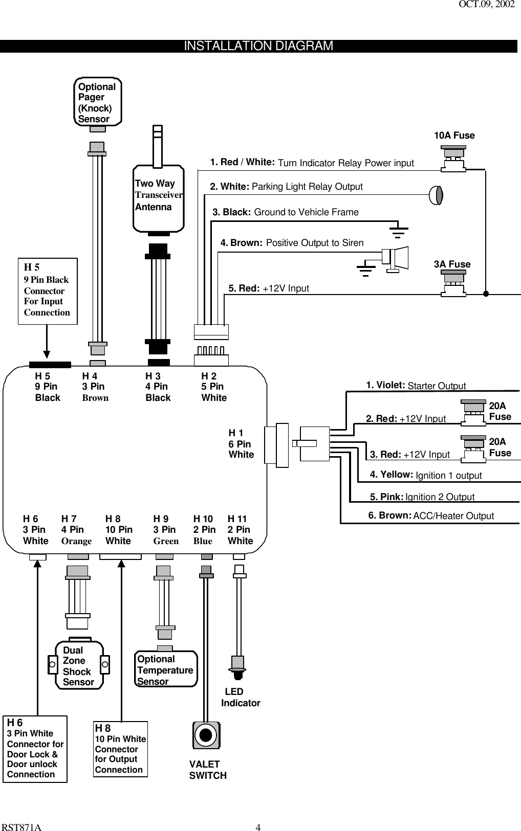
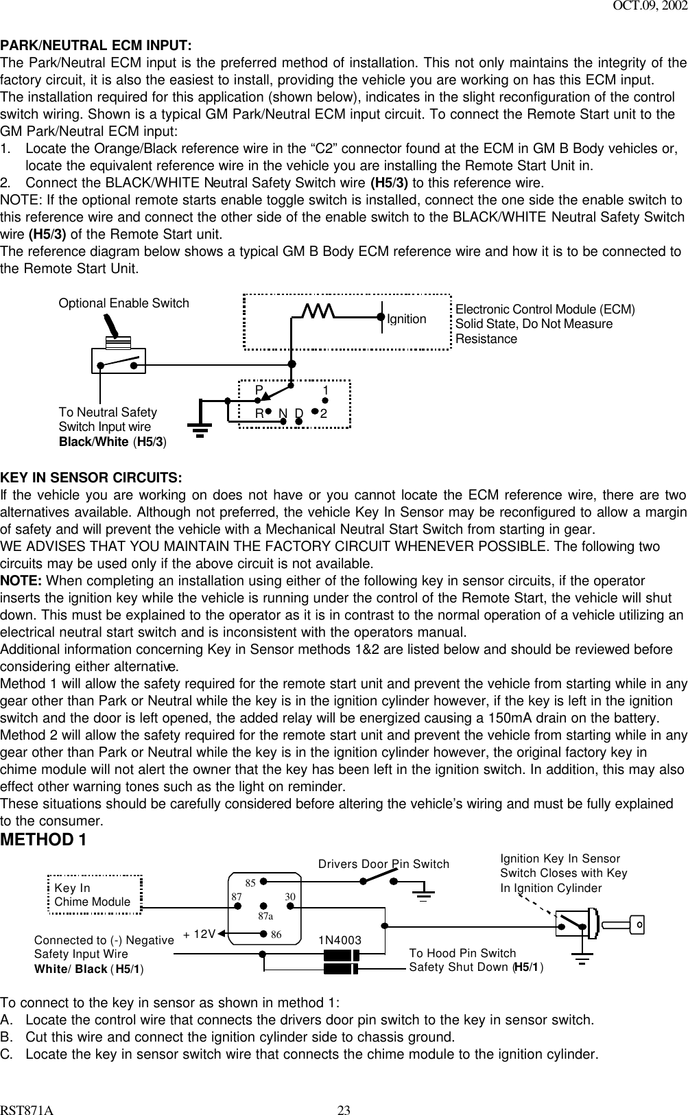
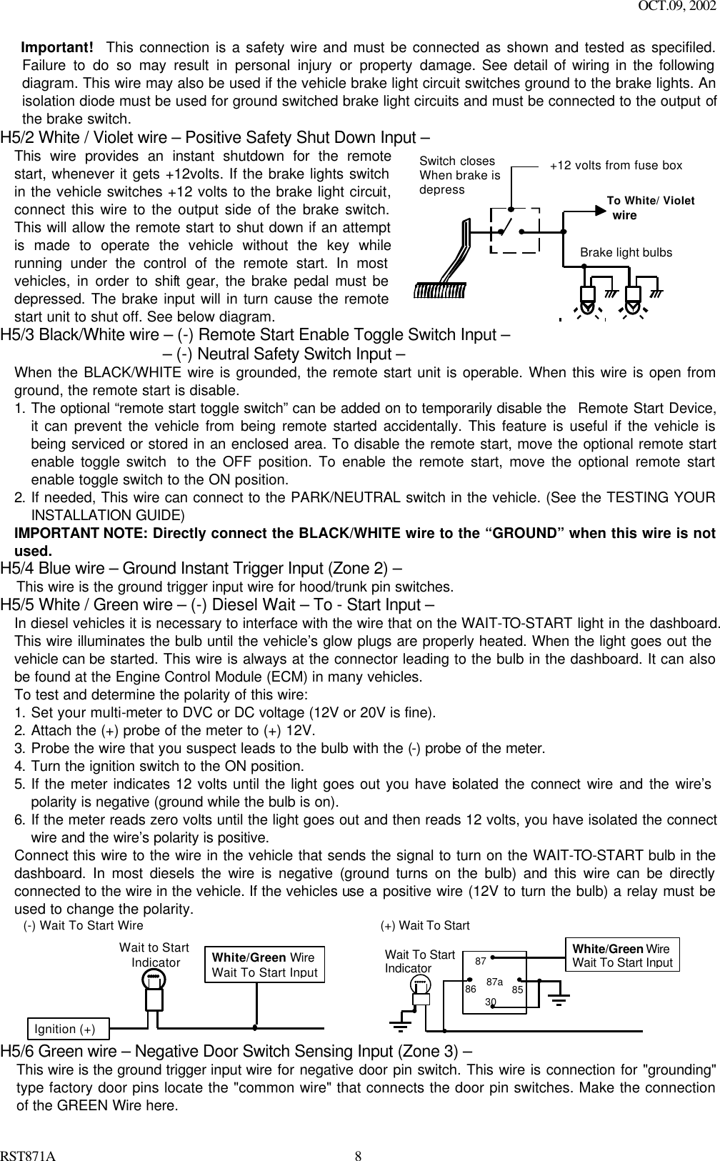
![OCT.09, 2002 RST871A 6WIRING Keep wiring away from moving engine parts, exhaust pipes and high-tension cable. Tape wires that pass through holes on the firewall to prevent fraying. Watches out sharp edges that may damage wires and causes short circuit. CAUTION: Do not connect the wire harness to the control module until all wiring to vehicle is complete. H1: 6 PIN HEAVY GAUGE WIRING CONNECTIONS: Remember that the system does to start a vehicle is duplicate the functions of the ignition key switch! Below, we will explain the three basic functions of the ignition switch. Since this installation will require analysis of the ignition switch functions, we recommend making the three connections below at the ignition switch harness directly. H1/1 Violet wire – Starter Output – Careful consideration for the connection of this wire must be made to prevent the vehicle from starting while in gear. Understanding the difference between a mechanical and an electrical Neutral Start Switch will allow you to properly identify the circuit and select the correct installation method. In addition you will realize why the connection of the safety wire is required for all mechanical switch configurations. Failure to make this connection properly can result in personal injury and property damage. In all installations it is the responsibility of the installing technician to test the remote start unit and assure that the vehicle can not start via RF control in any gear selection other than park or neutral. In both mechanical and electrical neutral start switch configurations; the connection of the VIOLET wire will be made to the low current start solenoid wire of the ignition switch harness. This wire has +12 volts when the ignition switch is turned to the “START” (CRANK) position only. This wire have 0 volts in all other ignition switch positions. NOTE: This wire must be connected to the vehicle side of the starter cut relay (when used). For the electrical neutral switch configuration, this connection must be made between the starter inhibit relay (when used) and the neutral safety switch as shown in the following diagram. Failure to connect this wire to the ignition switch side of the neutral safety switch can result in personal injury and property damage. SEE NEUTRAL START SAFETY TEST FOR FURTHER DETAILS. Start Cut Relay(When Used)VIOLET WireClosed in Park or Neutral OnlyIgnitionSwitch“Start”“On” Neutral SafetySwitch“Acc”“Off” Starter H1/2 & H1/3 Red wire – +12V Power Input – Remove the two 20A fuses prior to connecting these wires and do not replace them until the satellite has been plugged into the control module. These wires are the source of current for all the circuits the relay satellite will energize. They must be connected to a high current source. Since the factory supplies (+) 12V to the key switch that is used to operate the motor, it is recommended that these wires be connected there. Note: If the factory supplies two separate (+) 12V feeds to the ignition switch, connect one RED wire of the satellite to each feed at the switch. H1/4 Yellow wire – Ignition Output – Connect the YELLOW wire to the ignition wire from the ignition switch. The ignition wire should receive "12 volts" when the ignition key is in the "ON" or “RUN” and "START" or “CRANK” position. When the ignition is turned "OFF", the ignition wire should receive "0" voltage. The YELLOW wire must be connected. H1/5 Pink wire – Ignition 2 Output Some vehicles have [2] ignition wires that must be power. Connect the PINK wire to the ignition 2 wire from the ignition switch. The ignition wire should receive "12 volts" when the ignition key is in the "ON" or “RUN” and "START" or “CRANK” position. When the ignition is turned "OFF", the ignition wire should receive "0" voltage. If the PINK wire is not used, cap the end of the wire. H1/6 Brown wire – Accessory Output (Heater /ACC Output) – Connect the BROWN wire to the accessory wire in the vehicle that powers the climate control system. An accessory wire will show + 12 volts when the ignition switch is turned to the “ACCESSORY” or “ON” and “RUN” positions, and will show 0 Volts when the key is turned to the “OFF” and “START” or “CRANK” position. There will often be more than one accessory wire in the ignition harness. The correct accessory wire will](https://usermanual.wiki/Advance-Security/TR05/User-Guide-283064-Page-23.png)
![OCT.09, 2002 RST871A 14ROGRAMMING A. PROGRAMMING TRANSMITTER: PROGRAMMING THE REMOTE TRANSMITTER Note: This mode will only retain the last 4 remote transmitters programmed. If the transmitter memory is exceeded, the security system will start deleting transmitters from memory in chronological order. Enter: 1. Turn the Ignition 'switch ‘OFF/ON’ 3 TIMES and stay in ON position. Within 15 seconds. 2. Push the Valet switch 3 times and hold it until a long chirp is hearing then release the valet switch. You are now in the Transmitter programming mode. Program: 1. Press button on one of the transmitter until the siren responds with a confirming chirp the first transmitter is now programmed. 2. Press button on the second transmitter until the siren responds with a confirming chirp, the second transmitter is now programmed. 3. Apply the same procedure to program 3rd and 4th. Exit: Turn Ignition to 'OFF' position, or leave it for 15 seconds. A 3 long chirps & 3 parking light flashes to confirm exit. B. FEATURES PROGRAMMING: ALARM FEATURE “I” PRORAMMING: 1. Turn the Ignition 'switch ‘ON/OFF’ 3 TIMES and stay in OFF position. 2. Push the Valet switch 2 times and hold it until one chirp with a long chirp is hearing then release the valet switch. You are now in the Alarm feature ‘I’ programming mode. 3. Press and release the transmitter button ‘A’ corresponding to the feature ‘A’ you want to program. a. The siren chirps and LED pause will indicate previously setting. b. The factory default settings is always [1] LED flash, [1] chirp. 4 Depress the transmitter button ‘A’ a gain to change the feature. Simple keep re-depressing the transmitter button ‘A’ again until the module advances to your desired setting. a. In this case, Press button ‘A’ again, the module would advance to [2] LED flash, [2] chirps. b. Press button ‘A’ again, t he module would advance to [3] LED flash, [3] chirps etc. 5. Depress the transmitter button ‘B’ corresponding to the feature ‘B’ you wants to program. For example: To program the arming mode form “Active arming” to “Passive Arming without Passive Door Locking”, After “Arming mode” program, the next program is “Rearm on/off” .………. 1 Turn the Ignition 'switch ‘ON/OFF’ 3 TIMES and stay in OFF position. 2 Push the Valet switch 2 times and hold it until a chirp with a long chirp is hearing then release the valet switch. 3 Press and release the transmitter button corresponding to the feature ‘Arming mode’ you wants to program. [1] LED flash, [1] chirp to indicate your are in features “Active Arming”. 4 Depress the transmitter button twice to change the feature. [3] LED flash, [3] chirps to indicate your are in features “Passive Arming without Passive Door Locking ”. 5 Depress the transmitter button corresponding to the features ”Rearm on/off”’ you want to program…….. Press Transmitter Button One Chirp / LED one pulse Factory Default Setting Two Chirps / LED two pulses Three Chirps / LED three pulses Four Chirps / LED four pulses 1 All chirps on Siren chirp on only Horn chirp on only All chirps off 2 Active arming Passive arming without passive door locking Passive arming with passive door locking. 3 Automatic Rearm on Automatic Rearm off 4 3 seconds delay Door Ajar error chirp 30 seconds delay Door Ajar error chirp.](https://usermanual.wiki/Advance-Security/TR05/User-Guide-283064-Page-31.png)
![OCT.09, 2002 RST871A 16Press Transmitter Button One Chirp / LED one pulse Factory Default Setting Two Chirps / LED two pulses Three Chirps / LED three pulses Four Chirps / LED four pulses 1 Override Without Password Pin Code Override With Password Pin Code 2 H8/8 Pink Wire = Two step door unlock output H8/8 Pink Wire = Factory Security Disarm Signal Output H8/8 Pink Wire = Start Status Output (Shock Sensor Bypass) 3 4 H8/3 Brown / White Wire = (-) 200ma Horn Output H8/3 Brown / White Wire = Factory Security Rearm Signal Output H8/6 Black / Green Wire Channel 4 Output = Momentary output H8/6 Black / Green Wire Channel 4 Output = Latched output H8/6 Black / Green Wire Channel 4 Output = Latched output and reset with ignition “on” H8/6 Black / Green Wire Channel 4 Output = Timer programming (set to any interval between 1 second and 2 minutes.) 5 + Five Chirps / LED five pulse H8/6 Black / Green Wire = Key Sensor By-Pass Output (20second Ground output during the remote start is activated) 6 + H8/5 Black / Red Wire Channel 5 Output = Momentary output H8/5 Black / Red Wire Channel 5 Output = Latched output H8/5 Black / Red Wire Channel 5 Output = Latched output and reset with ignition “on” H8/5 Black / Red Wire Channel 5 Output = Timer programming (set to any interval between 1 second and 2 minutes.) 7 + H8/2 Black / Violet Wire Channel 6 Output = Momentary output H8/2 Black / Violet Wire Channel 6 Output = Latched output H8/2 Black / Violet Wire Channel 6 Output = Latched output and reset with ignition “on” H8/2 Black / Violet Wire Channel 6 Output = Timer programming (set to any interval between 1 second and 2 minutes.) Exit: Turn Ignition to 'ON' position, or leave it for 15 seconds. A 3 long chirps & 3 parking light flashes to confirm exit. Channel 4 (5 / 6) Timer Control Output Programming. Enter: 1. Turn the Ignition 'switch ‘ON/OFF’ 3 TIMES and stay in O FF position. 2. Push the Valet switch 6 times and hold it until three chirps with a long chirp is hearing then release the valet switch. You are now in the Alarm feature ‘III’ programming mode. Timer Program: 1-a. Press and release the transmitter + button 4 times, [4] LED flash, [4] siren/horn chirp to indicate your are in features “Channel 4 Timer Programming mode”. 1-b. Press and release the transmitter + button 4 times, [4] LED flash, [4] siren/horn chirp to indicate your are in features “Channel 5 Timer Programming mode”. 1-c. Press and release the transmitter + button 4 times, [4] LED flash, [4] siren/horn chirp to indicate your are in features “Channel 6 Timer Programming mode”.](https://usermanual.wiki/Advance-Security/TR05/User-Guide-283064-Page-33.png)
![OCT.09, 2002 RST871A 172. Press and hold the valet switch, the timer will immediately start. 3. When the desired interval has passed, release the valet switch. 1 long chirp for confirmation. (Set to any interval between 1 second and 2 minutes) Note 1: If your built-in timer controls window/sunroof closure in your car DO NOT change the timer setting! This requires installer-only programming. Changing the value will adversely effect operation and may cause damage. Note 2: Momentary output = The momentary output selection will output a negative signal from the Channel 4 (5/6) output immediately when the channel 4 (5/6) button is pressed and will continue until the button is release. Latched output = The latched output selection will output a negative signal as soon as the Channel 4 (5/6) button is pressed and will continue until the button is pressed again. Latched output / reset with ignition = The latched / reset with ignition output selection operates just like the latched output but will reset or stop when the ignition is turned on. Key Sensor By-Pass Output = The 20 seconds setting is for a Key sense wire by-pass that some Chrysler and Toyota vehicles need to activated remote start. It wire come on when the start is activated and stay on for 20 seconds. Password Pin Code Setup: Enter: 1. Turn the Ignition 'switch ‘ON/OFF’ 3 times and stay in OFF position. 2. Push the Valet switch 6 times and hold it until three chirps with a long chirp is hearing then release the valet switch. You are now in the Alarm feature ‘III’ programming mode. You can program or delete the password pin code as below: Program: 1. Press and release the transmitter button twice, [2] LED flash, [2] siren/horn chirp to indicate your are in features “Password Pin Code Programming mode”. 2. Within 5 seconds, begin to enter your chosen first 9ths digit by pressing and releasing the valet Switch from 1 – 9 times. 3. Within 15 seconds of the last entered 9ths digit, turn the Ignition switch to “ON” posi tion. 4. Within 15 seconds, enter your chosen second 9ths digit by pressing and releasing the valet Switch from 1 – 9 times. 5. Finish by turning the ignition switch to “OFF” position. If the new password code was accepted, the unit would report back the newly entered code, by flashing the LED, first indicating the first digit code has been memorized, pause and then the second digit code. The unit will report the new code three times with a one-second’s pause between each code. Note: If 15 seconds of inactivity expire, or if the ignition switch is turned “ON” for more then 5 seconds during of above steps, the unit will revert back to the last successfully stored code. A [3] long chirps to confirm exit. Will revert back to the last successfully stored code Delete Password Pin Code / Override Without Password Pin Code (Factory default setting): Within 15 seconds, press and hold the transmitter button for 3 seconds. A one long chirps to confirm Deleted the Password Pin Code. Example: To program the Password Code 92, you would; Enter: 1. Turn the Ignition 'switch ‘ON/OFF’ 3 times and stay in OFF position. 2. Push the Valet switch 6 times and hold it until three chirps with a long chirp is hearing then release the valet switch. You are now in the Alarm feature ‘III’ programming mode. Program: 1. Press and release the transmitter button once, [2] LED flash, [2] siren/horn chirp to indicate your are in features “Password pin code programming mode”. 2. Within 5 seconds, press and release the valet Switch 9 times. 3. Within 15 seconds of the last entered 9ths digit, Turn the Ignition Switch to “ON” position. 4. Within 15 seconds press the valet Switch twice. 5. Turn the Ignition Switch to “OFF’ position. You will note the LED flashing nine times, pause and then flash two times, pause. This pattern will be repeated three times indicating the new code (92) has been accepted and stored in memory.](https://usermanual.wiki/Advance-Security/TR05/User-Guide-283064-Page-34.png)
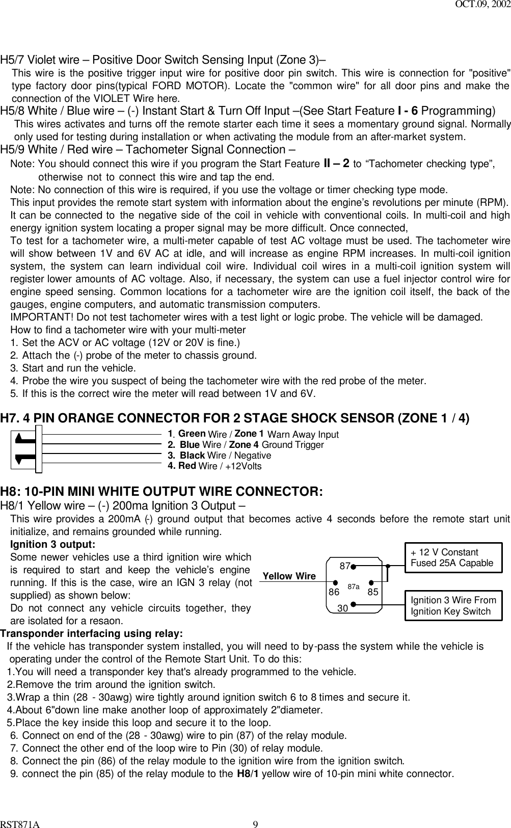
![OCT.09, 2002 RST871A 19RPM learning 3 Start Timer: 0.6-second 0.8-second (2 chirps), 1.0-second (3 chirps), 1.2-second (4 chirps), 1.4-second (5 chirps), 1.6-second (6 chirps), 1.8-second (7 chirps), 2.0-second (8 chirps), 3.0-second (9 chirps), 4.0-second (10 chirps), 4 Hi check level Low check level 5 - Start or Stop the system for TESTING & ADJUSTMENT 6 + “TEST” Mode for Zone 2 / instant trigger & Zone 3 / Door trigger “TEST” Mode for Zone 1 & Zone 4 (2 Stage Shock Sensor) Exit: Press the button on the transmitter. A 3 long chirps & 3 parking light flashes to confirm exit. TACHOMETER CHECKING TYPE Enter Start Feature ‘II’ Programming Mode: 1. Turn the Ignition 'switch ‘ON/OFF’ 3 TIMES an d stay in OFF position. 2. Push the Valet switch 10 times and hold it until five chirps with a long chirp is hearing then release the valet switch. You are now in the Start feature ‘II’ programming mode. Select “Checking Type”: 3. Press and release the transmitter and button at the same time once to set the “Tachometer Checking Type”. [1] LED flash, [1] chirp to Confirm this setting. 4. Once you complete step 3, you can program “RPM Learning Mode” as below: RPM Learning While the system stay in Start Feature “II” programming mode, 1. Press and release the transmitter button once, [1] LED flash, [1] chirp to indicate your are in features “RPM Learning mode”. 2. Start the vehicle with the key. (While the engine is running, the parking & LED will flash, If don’t, please check tachometer White/Red wire connection. (H5/9) 3. Press and hold the valet switch for 2 seconds until a long chirp and the LED light constant for two seconds. The RPM signal is learned. 4. Once you complete step 3, you can adjust and test “Check Level” as below: CHECK LEVEL PROGRAMMING: (TEST and ADJUST) While the system stay in Start Feature “II” programming mode, 1. Press the button twice on the transmitter to start the vehicle. 2. If everything goes well: a.Press the button twice on the transmitter to stop engine running. You have been completed this programming successfully. b.Press button on the transmitter to exit the program mode. There will be 3 long chirps & 3 parking light flashes for confirmation. 3. If the crank time is too long, (Engine already successfully running, while still cranks): a. Press the button twice on the transmitter to stop engine running. Press button on the transmitter to set proper “Check Level ” to Low position. [2] LED flash, [2] chirps to confirm this setting b. Repeat the step1 – 4. 4. If the crank time is too short, (Engine not running, while stops cranks): a. Press the button twice on the transmitter to stop engine running. Press button on the transmitter to set proper “ Check Level ” to Hi position. [1] LED flash, [1] chirp to confirm this setting b. Repeat the step1 – 4. VOLTAGE CHECKING TYPE Enter Start Feature ‘II’ Programming Mode: 1. Turn the Ignition 'switch ‘ON/OFF’ 3 TIMES and stay in OFF position.](https://usermanual.wiki/Advance-Security/TR05/User-Guide-283064-Page-36.png)
![OCT.09, 2002 RST871A 202. Push the Valet switch 10 times and hold it until five chirps with a long chirp is hearing then release the valet switch. You are now in the Start feature ‘II’ programming mode. Select “Checking Type”: 3. Press the transmitter and button at the same time to set the “Voltage Checking Type”. [2] LED flash, [2] chirp to confirm this setting 4. Once you complete step 3, you can adjust and test “Start Timer” as below: START TIMER PROGRAMMING: (TEST and ADJUST) While the system stay in Start Feature “II” programming mode, 1. Press the button twice on the transmitter to start the vehicle. 2. If everything goes well: Wait for 15 seconds: a. If the engine still running. I. Press the button twice on the transmitter to stop engine running. You have been completed this programming successfully. II. Press button on the transmitter to exit the program mode. There will be 3 long chirps & 3 parking light flashes for confirmation. b. If the engine shut down after the vehicle has been started. I. Press the ' button twice on the transmitter to stop engine running. II. Press button on the transmitter to set “Check Level” to LOW position. [2] LED flash, [2] chirp to confirm this setting III. Repeat the step1 – 2. 3. If the crank time is too long, (Engine already successfully running, while still cranks): a. Press the button twice on the transmitter to stop engine running. b. Press button on the transmitter to set proper “Start Timer”. The chirp & LED pause will confirm this enter. (Decrease “Start Timer” is necessary.) c. Repeat the step1 – 4. 4. If the crank time is too short, (Engine not running, while stops cranks): a. Press the button twice on the transmitter to stop engine running. b. Press button on the transmitter to set proper “Start Timer”. The chirp & LED pause wi ll confirm this enter. (Increase “Start Timer ” is necessary.) c. Repeat the step1 – 4. Timer Checking Type Enter Start Feature ‘II’ Programming Mode: 1. Turn the Ignition 'switch ‘ON/OFF’ 3 TIMES and stay in OFF position. 2. Push the Valet switch 10 times and hold it until five chirps with a long chirp is hearing then release the valet switch. You are now in the Start feature ‘II’ programming mode. Select “Checking Type”: 3. Press the transmitter and button at the same time to set the “Timer Checking Type”. [3] LED flash, [3] chirp to confirm this setting 4. Once you complete step 3, you can adjust and test “Start Timer” as below: START TIMER PROGRAMMING: (TEST and ADJUST) While the system stay in Start Feature “II” programming mode, 1. Press the button twice on the transmitter to start the vehicle. 2. If everything goes well: a.Press the ' button twice on the transmitter to stop engine running. You have been completed this programming successfully. b.Press button on the transmitter to exit the program mode. There will be 3 long chirps & 3 parking light flashes for confirmation. 3. If the crank time is too long, (Engine already successfully running, while still cranks): a.Press the button twice on the transmitter to stop engine running. b.Press the button on the transmitter to set proper “Start Timer”. The chirp & LED pause will confirm this enter. (Decrease “Start Timer” is necess ary.) c.Repeat the step1 – 4. 4. If the crank time is too short, (Engine not running, while stops cranks):](https://usermanual.wiki/Advance-Security/TR05/User-Guide-283064-Page-37.png)
![OCT.09, 2002 RST871A 21a.Press the button twice on the transmitter to stop engine running. b.Press button on the transmitter to set proper “Start Ti mer”. The chirp & LED pause will confirm this enter. (Increase “Start Timer ” is necessary.) c.Repeat the step1 – 4. TEST MODE In this test mode, this system can test the Zone 2 (Instant ground trigger), the Zone 3 (Door trigger), and the Zone 1 & Zone 4 (2 stage shock sensor) sensitivity. The installer can save time to test the 2 stage shock sensor sensitivity and sensor without using the traditional arming/disarming procedures to test the sensors. Enter: 1. Turn the Ignition 'switch ‘ON/OFF’ 3 TIMES and s tay in OFF position. 2. Push the Valet switch 10 times and hold it until five chirps with a long chirp is hearing then release the valet switch. You are now in the Start feature ‘II’ programming mode. a. Test the Zone 2 / Instant Ground Trigger & Zone 3 / Door Trigger: Press and release the transmitter and button at the same time once. [1] LED flash, [1] siren/horn chirp to indicate your are in Zone 2 / instant ground trigger and Zone 3 / Door trigger test mode. Trigger sensor Siren chirps Zone 2 / Instant Ground trigger (H5/4 Blue wire) 2 Zone 3 / Door trigger (H5/6 Green or H5/7 Violet wire) 3 b. Test the Zone 1 & Zone 4 / Two Stage Shock Sensor (Connected to H7 4 Pin Plug): Press and release the transmitter and button at the same time again. [2] LED flash, [2] siren/horn chirps to indicate your are in the shock sensor (connected to H7 4 pin plug) test mode. 1. Activate the warn-away (first stage of the shock sensor / Zone 1), system will emit a short chirp. 2. Activate the full alarm (second stage of the shock sensor / Zone 4), system will emit a long chirp. 3. Continue to test the shock sensor until reach the proper sensitivity. RETURN TO FACTORY DEFAULT SETTING: 1. Turn the ignition ON then OFF 3 TIMES and stay in OFF position. 2. Push the Valet switch 12 times and hold it until six chirp with a long chirp is hearing then release the valet switch. You are now in the “Return To Factory Default Setting” programming mode. 3. Press and hold the and button at the same time on the transmitter for 6 seconds, there will be a confirmation six chirp with 3 long chirp & 3 parking light flashes to confirm the system “Alarm Feature I & II & III Programming “ all returns to factory default setting then exit. Exit: Turn Ignition to 'ON' position, or leave it for 15 seconds. A 3 long chirps & 3 parking light flashes to confirm exit. SHUTDOWN DIAGNOSTICS The unit has the ability to report the cause of the last shutdown of the remote start system. Enter: 1. Turn the Ignition switch to ‘ON position. 2. Press the button on the transmitter. 3. The LED will now report the last system shutdown by flashing for one minute in the following grouped patterns: LED Flashes Shutdown Mode 1 (-) Safety Shutdown input (Hood) 1. Close the hood. 2. Check H5/1 White/ Black wire connection.](https://usermanual.wiki/Advance-Security/TR05/User-Guide-283064-Page-38.png)