Advanced Card Systems ACR122S PC Link Contactless Reader User Manual ACR122S PM V1 0
Advanced Card Systems Limited PC Link Contactless Reader ACR122S PM V1 0
Users Manual

Advanced Card Systems Ltd.
Website: www.acs.com.hk
Email: info@acs.com.hk
User Manual
A
AC
CR
R1
12
22
2S
S
P
PC
C-
-l
li
in
nk
ke
ed
d
C
Co
on
nt
ta
ac
ct
tl
le
es
ss
s
C
Ca
ar
rd
d
R
Re
ea
ad
de
er
r
ACR122S

Page 2 of 9
Universal Terminal UT1
Version 0.03 Oct 2008
\
ACR122S PC-linked Contractless Smart Card Reader
1.0 INTRODUCTION
der/Writer developed on the
13.56MHz Contactless Technology. This device is designed to support not only MiFare
and ISO14443 Type A and B Cards but also FeliCa and NFC tags.
By making use high-speed card access and Serial port speed of 115.200 Kbps, read and
write operations are faster and more efficient. With its compact size and trendy design
u can experience the convenience in
sit, physical access control, time
attendance, etc.
2.0 FEATURES
• Serial Interface. Baud Rate = 9600 bps (default) or 115200 bps, 8-N-1. Initial Baud Rate
is determined by the existence of R12. A command is also provided for changing the
baud rate while the reader is running.
• CCID-liked Frame Format.
• Support ISO14443 Part 4 Type A & B, MIFARE, FeliCa and NFC tags.
• Built-in Antenna for contactless tags access.
• Support ISO7816 T=0 cards. (SAM Socket)
• Bi-Color LED.
• Buzzer.
• 2 Relays (optional)
• 8 buffered TTL Input pins (optional)
• 8 buffered TTL Output pins (optional)
3.0 Typical Applications
• Network access control
• Micro-payment
• NFC mobile tag
• Public Transportation Terminals
• Automatic Fare Collection
• Physical access control
• Customer Loyalty
• Time attendance
• Contactless public phones
• Vending machines
The ACR122S is a PC-linked Contactless Smart Card Rea
and with the various features the ACR122S offers,yo
using ACR122S for applications of payment,mass tran

Page 3 of 9
Universal Terminal UT1
Version 0.03 Oct 2008
\
ACR122S PC-linked Contractless Smart Card Reader
4.0 Installation Procedure
and plug the USB cable into the
USB port. The USB is provided the power only. When the reader connects to the PC,
then the user can use it directly. It doesn’t need any windows driver to start up the reader.
5.0 Hardware Interfaces
5.1 Bi-Color LED
• User-controllable Bi-Color LED. Red and Green Color.
• The Green Color LED will be blinking if the “Card Interface” is not connected.
• The Green Color LED will be turned on if the “Card Interface” is connected.
• The Green Color LED will be flashing if the “Card Interface” is operating.
• The Red Color LED is controlled by the application only.
5.2 Buzzer
• User-controllable buzzer.
• The default Buzzer State is OFF
5.3 SAM Interface
• One SAM socket is provided.
5.4 Built-in Antenna
•
• The estimated size = 50mm x 40mm.
• The loop inductance should be around ~ 1.6uH to 2.5uH
• Operating Distance for different Tags ~ up to 50mm (depend on the Tag)
• No anti-collision. Only one Tag can be accessed at any one time.
Connect the ACR122S DB9 cable to the PC serial port
3 turns symmetric loop antenna.Center tapped.
Page 4 of 9
Universal Terminal UT1
Version 0.03 Oct 2008
\
ACR122S PC-linked Contractless Smart Card Reader
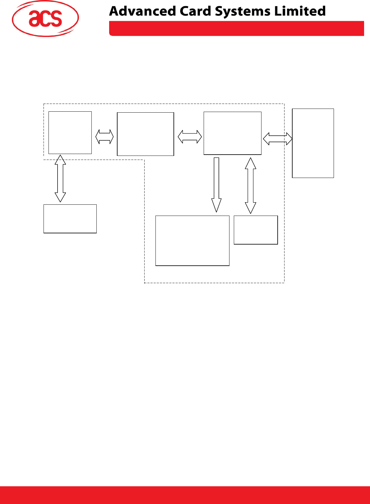
6.0 Implementation
ST7SCR1R4 and PN5321 chips.
PN5321
NFC Interface
Chip
ST7SCR1R4
Controller
Built-In
Antenna
Host
Controller
Serial
Interface
9600 bps
Contactless
Tag
Contactless Interface
Carrier = 13.56MHz
Serial Interface
115200 Kbps
SAM
(optional)
<Peripherals>
- Bi-Color LED
- Buzzer (optional)
- Relays
- I/O Ports
The ACR122S is built based on the
ACR122S System Block Diagram
Page 5 of 9
Universal Terminal UT1
Version 0.03 Oct 2008
\
ACR122S PC-linked Contractless Smart Card Reader
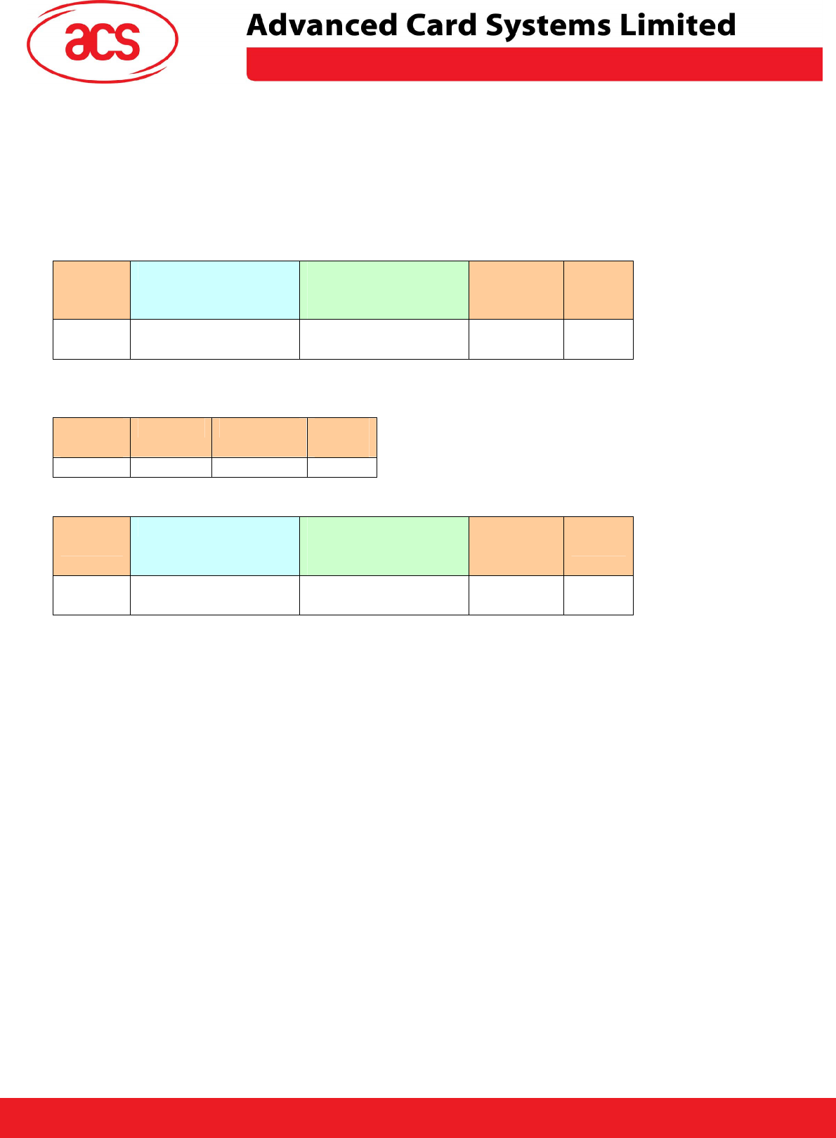
7.0 Serial Interface (CCID-liked FRAME Format)
Communication setting: 9600 bps, 8-N-1
The communication protocol between the Host and ACR122S is very similar to the CCID
protocol.
STX
(0x02)
Bulk-OUT Header APDU Command
Or
Parameters
Checksum ETX
(0x03)
1 Byte 10 Bytes M Bytes
(If applicable)
1 Byte 1 Byte
STX
(0x02)
Status Checksum ETX
(0x03)
1 Byte 1 Byte 1 Byte 1 Byte
STX
(0x02)
Bulk-IN Header APDU Response
Or
abData
Checksum ETX
(0x03)
1 Byte 10 Bytes N Bytes
(If applicable)
1 Byte 1 Byte
Checksum = XOR {Bulk-OUT Header, APDU Command or Parameters}
Checksum = XOR {Bulk-IN Header, APDU Response or abData}
In general, we would make use of three types of Bulk-OUT Header.
• HOST_to_RDR_IccPowerOn: To activate the SAM interface. The ATR of the SAM will be
returned if available.
• HOST_to_RDR_IccPowerOff: To deactivate the SAM interface.
• HOST_to_RDR_XfrBlock: To exchange APDUs between the Host and ACR122S-PM.
#The SAM interface must be activated in order to use the Contactless interface and
Peripherals. In short, all the APDUs are exchanged through the SAM Interface.
Similarly, two types of Bulk-IN Header are used.
• RDR_to_HOST_DataBlock: In response to the “HOST_to_RDR_IccPowerOn” and
“HOST_to_RDR_XfrBlock” Frames.
• RDR_to_HOST_SlotStatus: In response to the “HOST_to_RDR_IccPowerOff” Frame.
ACR122S Command Frame Format
ACR122S Status Frame Format
ACR122S Response Frame Format
HOST_to_RDR=Host Controller->ACR122S
RDR=ACR122S,HOST=Host Controller.
RDR_to_HOST=ACR122S->Host Controller
Page 6 of 9
Universal Terminal UT1
Version 0.03 Oct 2008
\
ACR122S PC-linked Contractless Smart Card Reader
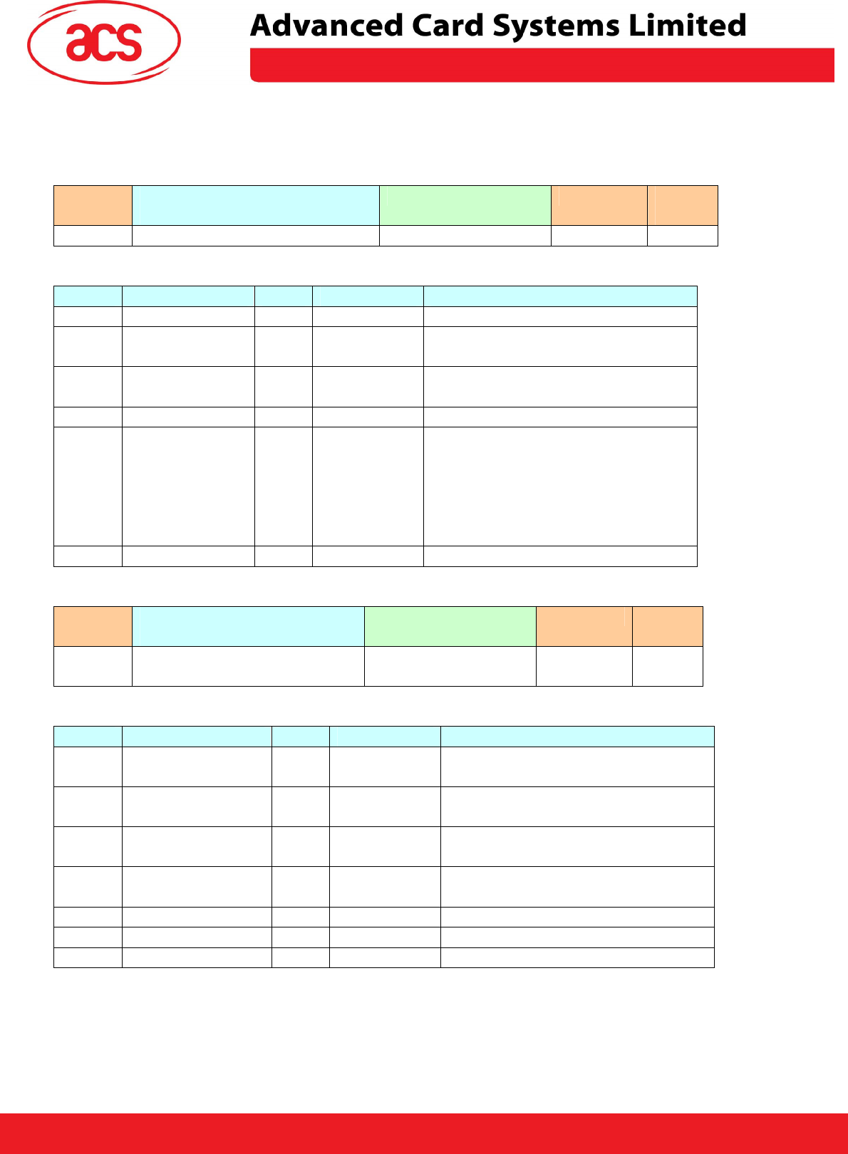
8.0 To activate the SAM Interface
STX
(0x02)
Bulk-OUT Header
(HOST_to_RDR_IccPowerOn)
Parameters Checksum
ETX
(0x03)
1 Byte 10 Bytes 0 Byte 1 Byte 1 Byte
HOST_to_RDR_IccPowerOn Format
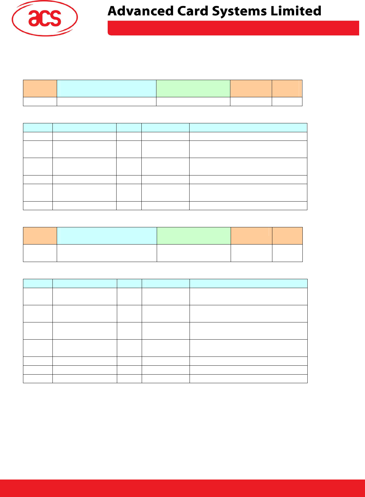
Offset Field Size Value Description
0 bMessageType
1 62h
1 dDwLength
<LSB .. MSB>
4 00000000h Message-specific data length
5 bSlot 1 00-FFh Identifies the slot number for this
command. Default=00h
6 bSeq 1 00-FFh Sequence number for command
7 bPowerSelect 1 00h, 01h,
02h, or 03h
Voltage that is applied to the ICC
00h – Automatic Voltage
Selection
01h – 5.0 volts
02h – 3.0 volts
03h – 1.8 volts
8 abRFU 2 Reserved for Future Use
STX
(0x02)
Bulk-IN Header
(RDR_to_HOST_DataBlock)
abData Checksum ETX
(0x03)
1 Byte 10 Bytes N Bytes
(ATR)
1 Byte 1 Byte
RDR_to_HOST_DataBlock Format
Offset Field Size Value Description
0 bMessageType 1 80h Indicates that a data block is
being sent from the ACR122S
1 dwLength
<LSB .. MSB>
4 N Size of abData field. (N Bytes)
5 bSlot
1 Same as
Bulk-OUT
Identifies the slot number for this
command
6 bSeq 1 Same as
Bulk-OUT
Sequence number for
corresponding command
7 bStatus 1
8 bError 1
9 bChainParameter
1
ACR122S Command Frame Format
ACR122S Response Frame Format
Page 7 of 9
Universal Terminal UT1
Version 0.03 Oct 2008
\
ACR122S PC-linked Contractless Smart Card Reader
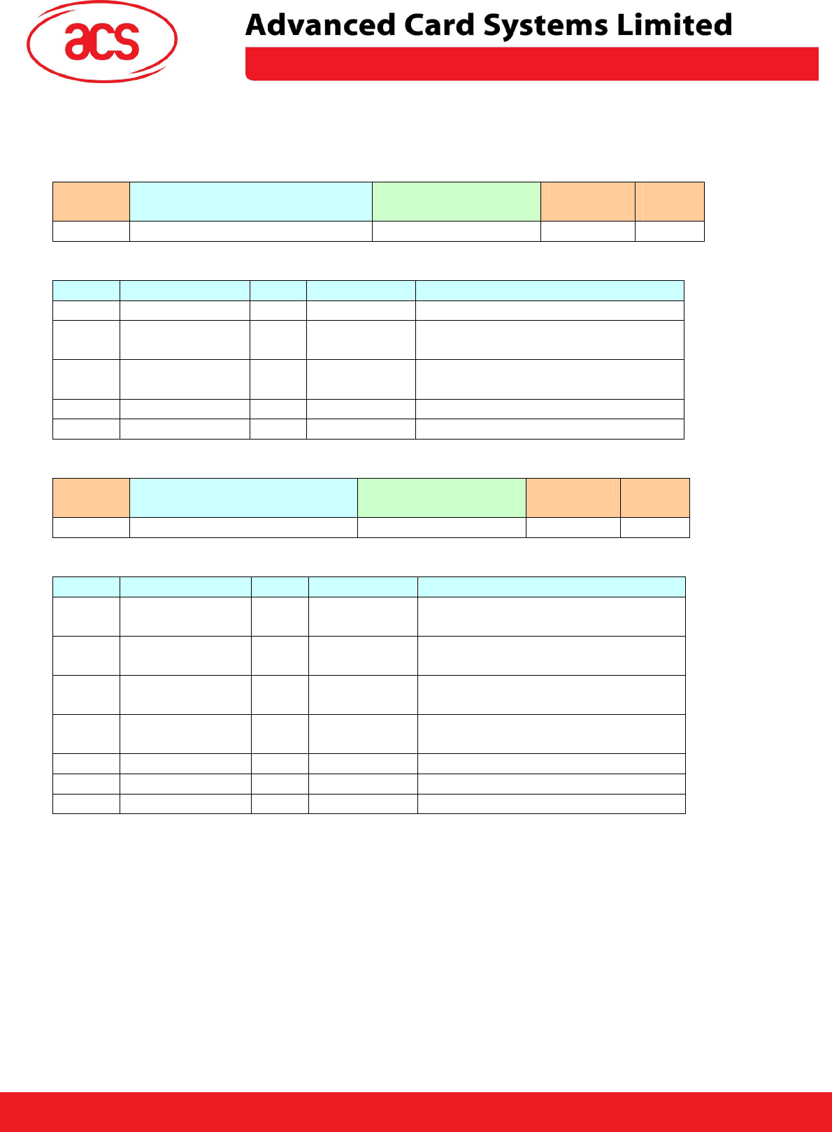
9.0 To deactivate the SAM Interface
STX
(0x02)
Bulk-OUT Header
(HOST_to_RDR_IccPowerOff)
Parameters Checksum
ETX
(0x03)
1 Byte 10 Bytes 0 Byte 1 Byte 1 Byte
HOST_to_RDR_IccPowerOff Format
Offset Field Size Value Description
0 bMessageType
1 63h
1 dDwLength
<LSB .. MSB>
4 00000000h Message-specific data length
5 bSlot 1 00-FFh Identifies the slot number for this
command. Default=00h
6 bSeq 1 00-FFh Sequence number for command
7 abRFU 3 Reserved for Future Use
STX
(0x02)
Bulk-IN Header
(RDR_to_HOST_SlotStatus)
abData Checksum ETX
(0x03)
1 Byte 10 Bytes 0 Byte 1 Byte 1 Byte
RDR_to_HOST_DataBlock Format
Offset Field Size Value Description
0 bMessageType
1 81h Indicates that a data block is
being sent from the ACR122S
1 dwLength
<LSB .. MSB>
4 0 Size of abData field. (0 Bytes)
5 bSlot
1 Same as
Bulk-OUT
Identifies the slot number for this
command
6 bSeq 1 Same as
Bulk-OUT
Sequence number for
corresponding command
7 bStatus 1
8 bError 1
9 bClockStatus 1
Example. To deactivate the slot 0 (default), sequence number = 2.
HOST -> 02 63 00 00 00 00 00 02 00 00 00 [Checksum] 03
RDR -> 02 00 00 03
RDR -> 02 81 00 00 00 00 00 02 00 00 00 [Checksum] 03
ACR122S Command Frame Format
ACR122S Response Frame Format
Page 8 of 9
Universal Terminal UT1
Version 0.03 Oct 2008
\
ACR122S PC-linked Contractless Smart Card Reader
10.0 To do data-exchange through the SAM Interface
STX
(0x02)
Bulk-OUT Header
(HOST_to_RDR_XfrBlock)
Parameters Checksum
ETX
(0x03)
1 Byte 10 Bytes M Byte 1 Byte 1 Byte
HOST_to_RDR_XfrBlock Format
Offset Field Size Value Description
0 bMessageType 1 6Fh
1 dDwLength
<LSB .. MSB>
4 M Message-specific data length
5 bSlot 1 00-FFh Identifies the slot number for this
command. Default=00h
6 bSeq 1 00-FFh Sequence number for command
7 bBWI 1 00-FFh Used to extend the Block Waiting
Timeout.
8 wLevelParameter 2 0000h
STX
(0x02)
Bulk-IN Header
(RDR_to_HOST_DataBlock)
abData Checksum ETX
(0x03)
1 Byte 10 Bytes N Bytes
(ATR)
1 Byte 1 Byte
RDR_to_HOST_DataBlock Format
Offset Field Size Value Description
0 bMessageType 1 80h Indicates that a data block is
being sent from the ACR122S
1 dwLength
<LSB .. MSB>
4 N Size of abData field. (N Bytes)
5 bSlot
1 Same as
Bulk-OUT
Identifies the slot number for this
command
6 bSeq 1 Same as
Bulk-OUT
Sequence number for
corresponding command
7 bStatus 1
8 bError 1
9 bChainParameter
1
Example 1. To send an APDU “80 84 00 00 08” to the slot 0 (default), sequence number = 3.
HOST -> 02 6F 05 00 00 00 00 03 00 00 00 80 84 00 00 08 [Checksum] 03
RDR -> 02 00 00 03
RDR -> 02 80 0A 00 00 00 00 03 00 00 00 E3 51 B0 FC 88 AA 2D 18 90 00 [Checksum] 03
Response = E3 51 B0 FC 88 AA 2D 18; SW1 SW2 = 90 00
ACR122S Command Frame Format
ACR122S Response Frame Format

ACR122S PC-linked Contractless Smart Card Reader
Universal Terminal UT1
Version 0.03 Oct 2008 Page 9 of 9
Warning:
This device complies with part 15 of the FCC Rules. Operation is subject to the following two conditions:
(1) This device may not cause harmful interference, and
(2) this device must accept any interference received, including interference that may cause undesired operation.
Changes or modifications not expressly approved by the party responsible for compliance could void the user's
authority operate the equipment.