Advanced Card Systems ACR122T Contactless Smart Card Reader and Writer User Manual
Advanced Card Systems Limited Contactless Smart Card Reader and Writer Users Manual
Users Manual
Advanced Card Systems Ltd. Website: www.acs.com.hk
Email:
info@acs.com.hk
A
AC
CR
R1
12
22
2T
T
Reference Manual
<ACR122T> <Feasibility Study>
Version <1.00> <31/03/2009>
Page
2
of
10
<
ACR122
T
>
Revision History
Version
Date Prepared By Description
V1.00 31.Mar.2009
Kit AU Preliminary specification for ACR122T

<ACR122T> <Feasibility Study>
Version <1.00> <31/03/2009>
Page
3
of
10
<
ACR122
T
>
Table of Contents
1.0. Introduction ................................................................................................................. 4
2.0. Feature ......................................................................................................................... 5
3.0. Hardware Interfaces ................................................................................................... 6
3.1. USB Interface ...............................................................................................................................6
3.2. Bi-Color LED ................................................................................................................................6
3.3. Built-in Antenna ............................................................................................................................6
4.0. Chips Selection........................................................................................................... 7
5.0. Implemenation............................................................................................................. 8
5.1. The ACR122T is built based on the AC1038 and PN5321 chips. ...............................................8
5.2. Communication between the Host and the Contactless interface and Peripherals.....................9
6.0. Software Interface..................................................................................................... 10

<ACR122T> <Feasibility Study>
Version <1.00> <31/03/2009>
Page
4
of
10
<
ACR122
T
>
1.0. Introduction
The ACR122T is a PC-linked Contactless cards Reader and writer for accessing ISO14443 Part 4
Type A contactless card.

<ACR122T> <Feasibility Study>
Version <1.00> <31/03/2009>
Page
5
of
10
<
ACR122
T
>
2.0. Feature
• USB Interface
• HID Standard
• No Driver Requested
• Build-in Antenna for contactless tags access.
• Support ISO14443 Part 4 Type A
• 13.56MHz Carrier Frequency Band
• Bi-Color LED.
• RoHS
• Small in size
<ACR122T> <Feasibility Study>
Version <1.00> <31/03/2009>
Page
6
of
10
<
ACR122
T
>
3.0. Hardware Interfaces
3.1. USB Interface
The ACR122T is connected to a Host through the USB as specified in the USB Specification 1.1. The
ACR122T is working in Full speed mode, i.e. 12Mbps.
Pin Signal Function
1 VCC +5V power supply for the reader (Max 200mA, Normal 100mA)
2 D- Differential signal transmits data between Host and ACR122T
3 D+ Differential signal transmits data between Host and ACR122T
4 GND Reference voltage level for power supply
3.2. Bi-Color LED
• User-controllable Bi-Color LED. Red and Green Color.
3.3. Built-in Antenna
• 6 turns symmetric loop antenna.
• The estimated size = 19mm x 19mm.
• The loop inductance should be around ~ 1.6uH to 2.5uH
• Operating Distance for different Tags ~ up to 10mm (depend on the Tag)
• No anti-collision. Only one Tag can be accessed at any one time.

<ACR122T> <Feasibility Study>
Version <1.00> <31/03/2009>
Page
7
of
10
<
ACR122
T
>
4.0. Chips Selection
The AC1038 (ST7SCR) will be used as the main core for the reader. The reasons are listed below:
1. The AC1038 (ST7SCR) has been used in our current readers for a long time. This chip is
considered stable and mature
2. Little change on the existing USB and Contactless Cards access portions of the ACR122U
firmware can be used.
3. The AC1038 (ST7SCR) supports USB Interface
4. The AC1038 (ST7SCR) provides sufficient I/O pins for driving the RF Interface chip
5. The AC1038 (ST7SCR) is RoHS compliant
6. ST provides a good technical support on AC1038 (ST7SCR)
7. The development tools for AC1038 (ST7SCR) are available. It can save the development charge
8. The development effort and time can be significantly shorten if the AC1038 (ST7SCR) be used
The PN532 will be used as an RF Interface chip. The reasons are listed below:
1. The PN532 supports ISO14443 Type A, B, NFC and FeliCa Protocols and Interface
2. Only two pins is required for the communication with the controller via High Speed serial
Interface
3. The chip is small in size, it can help to reduce the size of the overall product.
4. The PN532 is RoHS compliant
5. The supplier of the N532 is NXP, which is well-know company. They provided good technical
support on their product
6. Currently use in ACR122U, save the time on development
<ACR122T> <Feasibility Study>
Version <1.00> <31/03/2009>
Page
8
of
10
<
ACR122
T
>
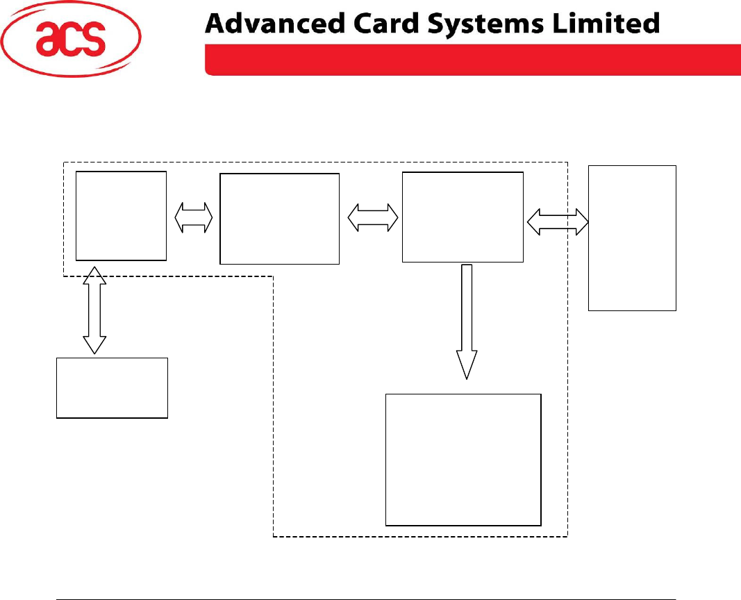
5.0. Implemenation
5.1. The ACR122T is built based on the AC1038 and PN5321 chips.
PN5321
NFC Interface
Chip
AC1038
Host Controller
Built-In
Antenna
Host
Controller
USB
Interface
12Mbps
Contactless
Tag
Contactless Interface
Carrier = 13.56MHz
Serial Interface
115
200 Kbps
Figure 1.ACR122T System Block Diagram
<Peripherals>
- Bi-Color LED
- Buzzer (optional)
- I/O Ports
<ACR122T> <Feasibility Study>
Version <1.00> <31/03/2009>
Page
9
of
10
<
ACR122
T
>
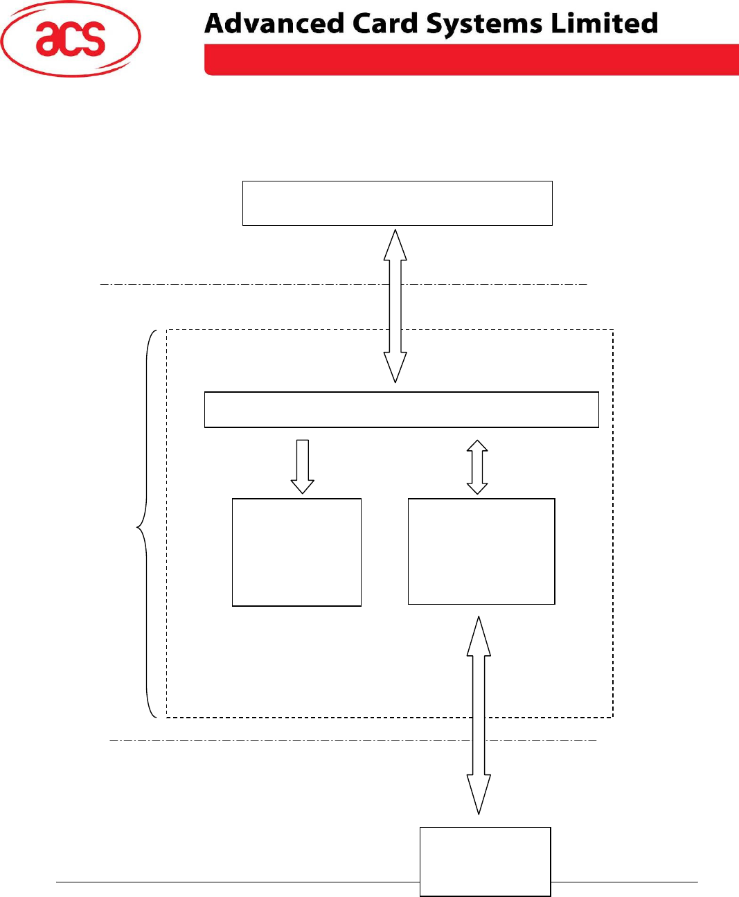
5.2. Communication between the Host and the Contactless
interface and Peripherals.
The Contactless interface & Peripherals are accessed through the use of HID Command Pattern.
USB
Interface
(HID protocol)
ACR122T
RF
Interface
Contactless
Interface
Contactless Tag
(Built-In Antenna)
Host
NON-PCSC Layer
1) Peripherals
2) Bi-Color LED

<ACR122T> <Feasibility Study>
Version <1.00> <31/03/2009> Page 10 of 10
<ACR122T>
6.0. Software Interface
Non PCSC interface is used for exchanging APDUs and Responses between the Host and Tag. The
ACR122T is only used as transceiver. The ADPUs and Responses are transparent to the ACR122T.
ACR122T will come with the following commands for this purpose.
1. Card Polling
To request response from contactless card within the antenna access area, the serial number of
the contactless card will be returned
2. APDU Transmit
To send an APDU (PN532 and Contactless cards Commands), and the Data will be returned
3. Bi-Color LED Control
To control the status of the Bi-Color LED
4. Reset Antenna
To reset the Build-in Antenna
FCC Warning:
This device complies with part 15 of the FCC Rules. Operation is subject to the following two conditions:
(1) This device may not cause harmful interference, and
(2) this device must accept any interference received, including interference that may cause undesired operation.
Changes or modifications not expressly approved by the party responsible for compliance could void the user's
authority to operate the equipment.