Advanced Control Technologies 0778-0X Lighting Controller User Manual ZDP100 S300 R4 1 instr p65
Advanced Control Technologies, Inc. Lighting Controller ZDP100 S300 R4 1 instr p65
Manual
Z-Wave ZDP100 Instructions, Series 300, Release 4.1
052909
HomePro
by ADVANCED CONTROL TECHNOLOGIES, INC.
0778-01
1
Z-Wave Radio Frequency (RF) Controlled, 300W, 120 VAC,
Plug-In Lamp Module, Series 300, Release 4.1
ZDP100
HomePro
RF Home Automation
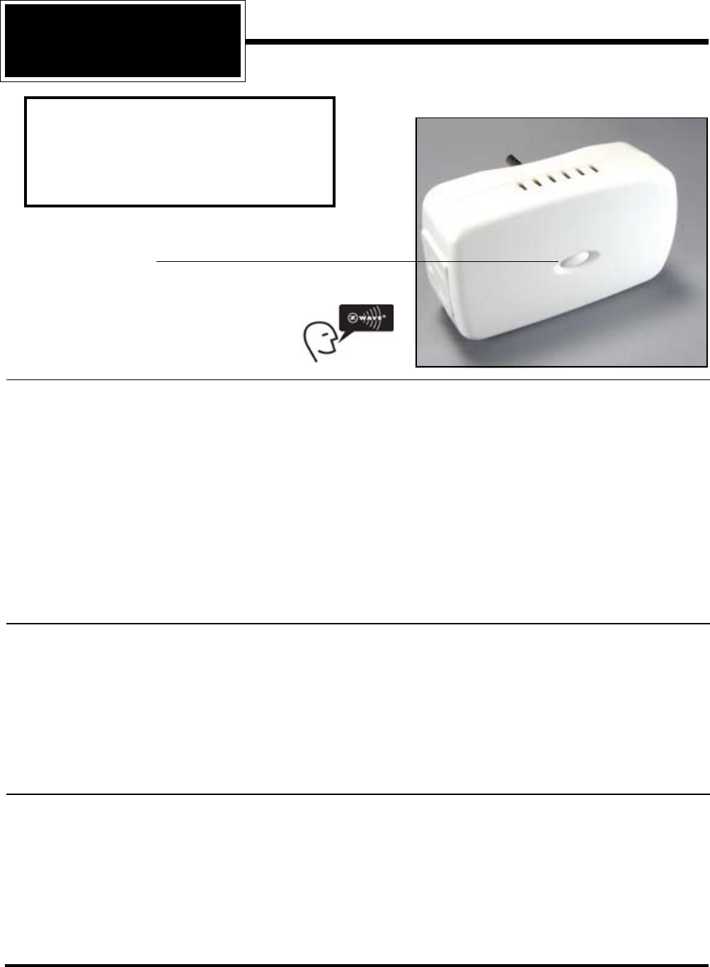
Button functions
1. Use to include module under the command of a Controller.
2. Local ON and OFF (push and release).
3. Local dimming (hold down).
ZDP100 PLUG-IN LAMP MODULE
The ZDP100 plug-in Lamp Module is a component of the HomePro lighting control system. Plug the Lamp Module
into a wall outlet and plug a lamp into the controlled outlet of the Lamp Module. Inclusion of the ZDP100 Lamp Module
on the ZTH100 Wireless Controller menu allows remote ON/OFF control and dimming of lamps connected.
This plug-in Lamp Module is designed to work with other Z-Wave enabled devices. Z-Wave nodes of other types can
be included in the system and will also act as repeaters if they support this function of repeating the signal received
to other modules in the system.
This product supports 40Kbps data transmission. This product can also be used for networking support in
systems that stream metadata. An example might include transmission of information from audio devices such as
song title, artist, and album information to various displays around the home.
As part of a Z-Wave network, the ZDP100 can act as a wireless repeater to insure that commands intended for another
device in the network are received. This is useful when the device would otherwise be out of the radio range of the
wireless controller.
INSTALLATION
Plug this Lamp Module into the wall outlet near the lamp to be controlled, and plug the lamp into the Lamp Module. Make
sure the lamp(s) to be controlled total no more than 300 watts. To reduce the risk of electric shock, this product has a
grounding type plug that has a third (grounding) pin. This plug will only fit into a grounding type power outlet. If the plug
does not fit into the outlet, contact a qualified electrician to install the proper outlet. Do not change the plug in any way.
WARNING: Plugging a non-resistive load such as florescent lighting or a device with a motor may result in damage
to the Lamp Module and will void the warranty. Note: Grounded outlet is always powered and can be used for any
other appliance. See the ZTH100 or other Wireless Controller operating instructions for details to include this module
under the command of the Wireless Controller.
INCLUDING ZDP100 TO THE NETWORK
STEP 1.. Prepare the Controller to include a unit to the network by adding it to a group (method of adding a
node to the network). Refer to controller instructions.
STEP 2. The ZDP100 must be in its permanently installed location. Tap the button on the ZDP100 once.
STEP 3. You should see an indication on your Controller that the “DEVICE WAS INCLUDED” in the network.
NOTE: If you have trouble adding the ZDP100 to a group it may be that the Home ID and Node ID were not
cleared from it after testing. You must first “RESET UNIT” with your controller to remove it from the network.
If using the ZTH100 select “SETUP” and scroll to “RESET UNIT”. Although adding it to a group includes it in
the network, removing it from a group does not remove it from the network. If removed from a group, it just
functions as a repeater.
• This product supports Zensor Net Beam technology.
Note: This module must be “Included in the
Network” only where it will be permanently
installed. You cannot “test bench” configure this
module, then install. The proper operation of this
node in the mesh network is dependent on it
knowing its location with respect to other nodes.

Z-Wave ZDP100 Instructions, Series 300, Release 4.1
052909
HomePro
by ADVANCED CONTROL TECHNOLOGIES, INC.
0778-01
2
BASIC OPERATION
Local Control
The button on the ZDP100 allows the user to
•Turn ON, OFF or DIM and BRIGHTEN the load attached to the controlled outlet.
•Include or exclude the module from the Z-Wave system
When a controller prompts you to “Send Node ID” or to “Press Button on Unit”, quickly tap the button on the ZDP100
once to satisfy those instructions. Further operation of button:
• Tapping button toggles the load attached
•Pressing and holding the button will dim or brighten the load attached.
Operation Note
When a light bulb reaches the end of it’s life and burns out, it sometimes creates a momentary short circuit. The
high current that results may cause the dimmer to respond by turning off. Should this happen, replace the bulb
with a new one. The dimmer can now be operated to restore power to the light.
Remote Control
The ZDP100 will respond to BASIC and MULTILEVEL commands that are part of the Z-Wave system. Refer to
your controller’s instructions as to whether your controller can transmit those commands.
See the information in the section titled Version for a complete list of commands the ZDP100 will support.
ADVANCED OPERATION
Protection
The ZDP100 supports the Protection Command.
The ZDP100 can be set to any one of 3 Protection modes by a wireless controller. Refer to your controller for
information on how to set the various modes of Protection. Some controllers may only be able to set certain settings
of Protection.
There are 3 modes of Protection:
1. No Protection
2. Child Protection
3. Button on ZDP100 totally disabled
When Protection is set to “No Protection” mode, the ZDP100 works normally.
When Protection is set to “Child Protection” mode, you will have to press the button 3 times rapidly to toggle the
attached load. Tap the button twice then press and hold it to dim or brighten the attached load. The ZDP100
operates normally if controlled by a wireless controller.
When Protection is set to “Enable Total Protection” mode, the button will not work. You will be able to turn the load
on and off only with a wireless controller, however the button can still be used to access the Z-Wave network for
programming.
All On/All Off
The ZDP100 supports the ALL ON/ ALL OFF commands.
The ZDP100 can be set to respond to ALL ON and ALL OFF commands 4 different ways.
Refer to your controller for information on how to set the ZDP100 to operate in the manner you desire. Some
controllers may be only able to set certain settings of ALL ON/ALL OFF response.
The 4 different ways the ZDP100 can be setup to respond to ALL ON and ALL OFF commands are:
• ZDP100 will not respond to ALL ON or the ALL OFF command.
• ZDP100 will respond to ALL OFF command but will not respond to ALL ON command.
• ZDP100 will respond to ALL ON command but will not respond to ALL OFF command.
• ZDP100 will respond to ALL ON and the ALL OFF command.

Z-Wave ZDP100 Instructions, Series 300, Release 4.1
052909
HomePro
by ADVANCED CONTROL TECHNOLOGIES, INC.
0778-01
3
Configuration
The ZDP100 supports the Configuration command.
The ZDP100 can be configured to operate slightly differently than it works when you first install it. Using the
configuration command you can configure the following (if your controller supports it):
You can use a HomePro ZTH100 Wireless Controller to send Configuration commands. (Refer to the Setup Menu,
Configuration section)
Load Sense:
• Parameter No: 29
• Length: 1 Byte
• Valid Values = 0 or 1 (default 1)
Set this parameter to 0 to disable load sense. Set this parameter to 1 to enable load sense.
Manufacturer Specific
The ZDP100 supports the Manufacturer Specific command.
The ZDP100 can return Manufacturer Specific information about itself. Refer to your controller’s instructions on
how to get this information from the ZDP100 (ZTH100 does not display this).
SUC Support
There must be a Static Update Controller in your Z-Wave system for this feature to work. The Static Controller
can act as a gateway in the system, since other nodes always know its position (it is never moved after inclusion
to the network). The “always listening” advantage of the Static Controller is that other nodes can transmit
information frames to it whenever needed.
You can assign an “SUC Route” to the ZDP100. Refer to your controller’s instructions on how to do this (if it supports
it). Assigning an SUC Route to the ZDP100 allows it to request an update of the Z-Wave devices that are between
it and the Z-Wave device to which it was trying to transmit. The ZDP100 will only request an update when a
transmission fails.
SPECIFICATIONS
Power 120 VAC, 60 Hz
Signal (Frequency) 908.42 MHz
Maximum Load 300 W, for incandescent lamps only. Note: A minimum 25 watt load is
recommended for the “load sense” feature and dimming capabilities of
this product to operate properly.
Range Up to 100 feet line of sight between the Wireless Controller and/or the
closest HomePro plug-In Lamp Module or Appliance Module
INTEROPERABILITY WITH Z-WAVE™ DEVICES
A Z-Wave™ network can integrate devices of various classes, and these devices can be made by different
manufacturers. The ZDP100 can be incorporated into existing Z-Wave™ networks.
The button on the face of the ZDP100 can be used to carry out inclusion (add to a group), exclusion (remove from
group) or reset (remove from network).
Software Fuse
The ZDP100 is designed to protect itself against loads that exceed it’s maximum power rating. The application
of a load that exceeds that rating is quickly sensed by the dimmer and it responds by immediately shutting off all
power to that load. If the dimmer doesn’t seem to work, or if it only works momentarily, check to see that the total
lamp wattage doesn’t exceed the 300W rating of the ZDP100. If a properly sized load is restored to the dimmer,
it can be operated normally once again.
Over-current protection
The ZDP100 hardware has an over current detection circuit, which is final protection against overload. If the
software fuse should fail to shut down the dimmer when overloaded, backup protection is provided by an internal
fuse. This fuse is not user serviceable. Check your home circuit breakers before concluding that the product must
be returned to the manufacturer for repair at a nominal charge.

Z-Wave ZDP100 Instructions, Series 300, Release 4.1
052909
HomePro
by ADVANCED CONTROL TECHNOLOGIES, INC.
0778-01
4
WARRANTY
For warranty and general product information visit our web site at www.act-solutions.com
FCC NOTICE
Note: This equipment has been tested and found to comply with the
limits for a Class B digital device, pursuant to part 15 of the FCC
Rules. These limits are designed to provide reasonable protection
against harmful interference in a residential installation. This equip-
ment generates, uses, and can radiate radio frequency energy and,
if not installed and used in accordance with the instructions may
cause harmful interference to radio communications. However, there
is no guarantee that interference will not occur in a particular instal-
lation. If this equipment does cause harmful interference to radio or
television reception, which can be determined by turning the equip-
ment off and on, the user is encouraged to try to correct the interfer-
ence by one or more of the following measures:
- Reorient or relocate the receiving antenna.
- Increase the separation between the equipment and receiver.
- Connect the equipment into an outlet on a circuit different from that to which the receiver is connected.
- Consult the dealer or an experienced radio/TV technician for help.
IC NOTICE
This Class B digital apparatus complies with Canadian ICES-003.
Cet appareil numérique de la classe B est conforme à la norme NMB-003 du Canada.
Operation is subject to the following two conditions: (1) this device may not cause interference, and (2) this device must
accept any interference, including interference that may cause undesired operation of the device.
About ZDP100’s Certification
In addition to compliance with product safety standards, the ZDP100 is also certified to comply with applicable FCC
and IC rules and regulations governing RF and EMI emissions.
Changes or modifications not expressly approved by the party responsible for compliance could void the user’s
authority to operate the equipment.
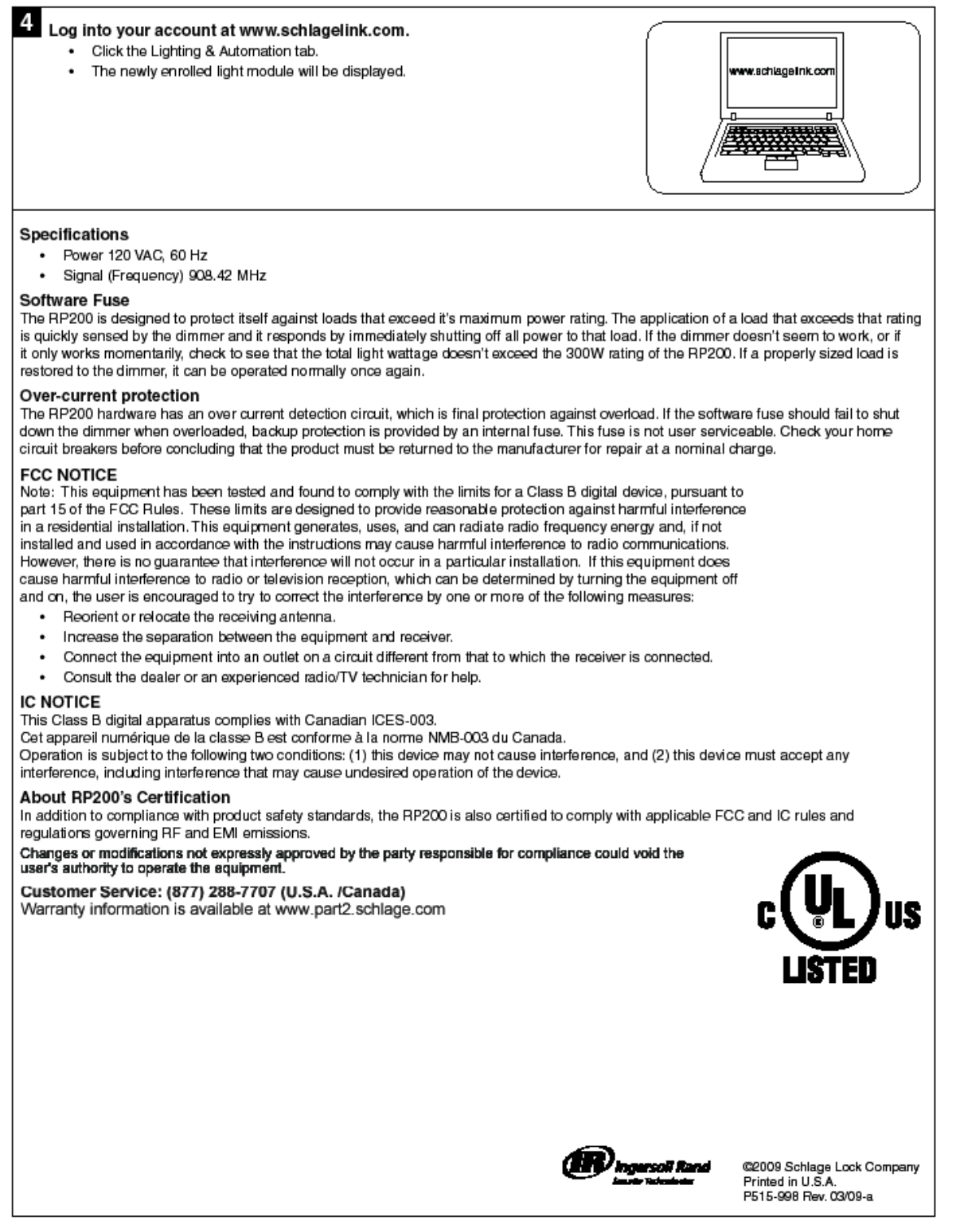
RP200
Light Module
P515-998
FOR INDOOR USE ONLY!
DO NOT use with non-resistive loads, such as florescent lighting, CFL bulbs or motors.
To reduce the risk of electric shock, this product has a grounding type plug that has a third (grounding) pin.
This plug will only fit into a grounding type power outlet. If the plug does not fit into the outlet, contact a
qualified electrician to install the proper outlet. Do not change the plug in any way.
Any modification or use other than described may damage the unit and will void the warranty.
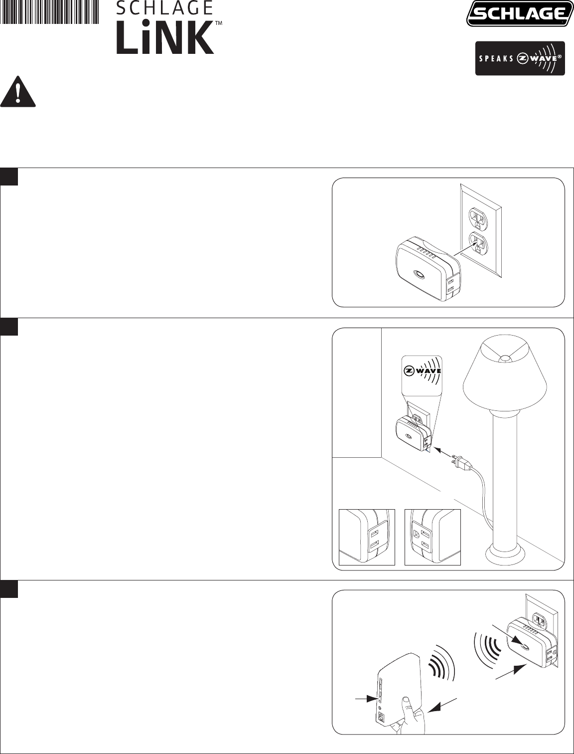
Install the light module.
Install into any indoor, three-prong, 120 volt A/C outlet.•
1
(Optional) Plug a lamp into the Z-Wave™ (two-prong) side of
the light module.
A lamp (25 watts minimum and 300 watts maximum) can be •
controlled through Z-Wave™ side of light module.
DO NOT use a CFL (compact fluorescent light bulb). •
The light module works like a dimmer switch and will not function
properly with CFL and LED bulbs or electric devices with motors,
like fans.
Make sure that lamp switch is in the ON position.•
Pass-through (three-prong) outlet (1500 watts maximum) is NOT •
controlled by the system and functions as a standard electrical
outlet.
2
Max. 300W
Incandescent
Z-Wave™
Side
Pass-through
Side
Enroll the light module into the bridge.
Disconnect power and Ethernet from the bridge.a.
Install a new 9 volt battery into the bridge.b.
Hold the bridge within 6 feet (1.8 meters) of the light module c.
throughout all of step 3.
Press and release the plus (+) button on the bridge.d.
Double-click the button on the light module.e.
Observe the lights on bridge. The orange light will blink while f.
enrollment is taking place. Enrollment is complete when the
orange light becomes solid.
Reconnect power and Ethernet to the bridge.g.
3
First
Press
+
Then Press
Within
6’ (1.8 m)
