Advanced RF Technologies ADX-R-730S DAS(Distributed Antenna System) User Manual ADX DAS V0 3
Advanced RF Technologies, Inc. DAS(Distributed Antenna System) ADX DAS V0 3
ADX-R-730S_User Manual-rev1
Advanced RF Technologies, Inc. i
ADX DAS User Manual
Version 0.3
:HVW9DQRZHQ6W
%XUEDQN&$
7HO
)D[
ZZZDGUIWHFKFRP

Advanced RF Technologies, Inc. ii
Information in this document is subject to change without notice.
Advanced RF Technologies, Inc. 1996-2012.
All rights reserved.
x Please send comments to:
E-Mail: info@adrftech.com
Phone: (818) 840-8131
(800) 313-9345
Fax: (818) 840-8138
x Address:
Advanced RF Technologies, Inc.
Attention: Technical Publications Department
3116 Vanowen St.
Burbank, CA 91505
USA
www.adrftech.com
Advanced RF Technologies, Inc. iii
Revision History
Change List
9HUVLRQ &KDQJHOLVW &RQWHQWV
9HUVLRQ $XWKRU 'HVFULSWLRQV 'DWH
0.1 BC Kim Initial Release
0.2 Sun Kim Edited version of the initial release 2/28/12
0.3 YHKO HE, RU PSU Back panel Fig. revised, HE Back side Fig. revised 3/8/12

Advanced RF Technologies, Inc. iv
Table of Contents
1. Introduction........................................................................................................................................14
1.1 Highlights ....................................................................................................................................14
1.2 Parts List .....................................................................................................................................15
1.2.1 HE Part Lists ........................................................................................................................15
1.2.2 RU Part Lists ........................................................................................................................18
1.3 ADX DAS Quick View .................................................................................................................20
1.3.1 HE Quick View .....................................................................................................................20
1.3.2 RU Quick View .....................................................................................................................21
1.4 Warnings and Hazards ...............................................................................................................22
2. Block Diagram ...................................................................................................................................24
2.1 ADX DAS Block Diagram............................................................................................................ 24
2.2 ADX DAS Topology ....................................................................................................................25
2.3 SISO Configuration.....................................................................................................................26
2.4 MIMO configuration ....................................................................................................................27
2.5 ADX-DAS Scalability...................................................................................................................28
3. ADX Overview ...................................................................................................................................29
3.1 Head End ....................................................................................................................................29
3.1.1 NMS (Network Management System) .................................................................................30
3.1.1.1 LEDs............................................................................................................................ 30
3.1.1.2 Ethernet Port ...............................................................................................................31
3.1.1.3 Host/Remote Switch....................................................................................................31
3.1.1.4 HE View/RU View Switch............................................................................................31
3.1.2 RFU (ADX-H-RFU-x)............................................................................................................32
3.1.2.1 LEDs............................................................................................................................ 32
3.1.2.2 RF Ports ...................................................................................................................... 33
3.1.2.3 Communication Port....................................................................................................33
3.1.3 Channel Combiner (ADX-H-CHC)........................................................................................33
3.1.3.1 RF ports.......................................................................................................................33
3.1.4 Optic Unit (ADX-H-OPT) ......................................................................................................34
3.1.4.1 LEDs............................................................................................................................ 34
3.1.4.2 RF ports.......................................................................................................................34
3.1.4.3 Optic ports ...................................................................................................................35
3.1.4.4 Communication Port....................................................................................................35
3.1.5 Power Supply Unit (ADX-H-PSU) ........................................................................................35
3.1.5.1 LEDs............................................................................................................................35
3.1.5.2 AC Input On/Off Switch, AC Input Port and AC Input Selection Switch......................36
3.1.5.3 Battery Backup Port, Battery Install Port and Battery Backup Switch ........................36
3.1.6 Optional Band Combiner Unit (ADX-H-BCU-x)....................................................................37

Advanced RF Technologies, Inc. v
3.1.6.1 LEDs............................................................................................................................ 37
3.1.6.2 RF Ports ...................................................................................................................... 37
3.1.6.3 Communication Port....................................................................................................37
3.1.7 Optional Optic Expansion Unit (ADX-H-OEU) .....................................................................38
3.1.7.1 LEDs............................................................................................................................38
3.1.7.2 Optic ports ...................................................................................................................38
3.1.7.3 DC Power Input port & GUI Port .................................................................................39
3.1.7.4 Power On/Off Switch & ADDR ....................................................................................39
3.1.7.5 OEU Block Diagram ....................................................................................................39
3.2 RU (ADX-R-x30M/S)...................................................................................................................41
3.2.1 Master RU (ADX-R-x30M) ...................................................................................................42
3.2.1.1 LEDs............................................................................................................................ 42
3.2.1.2 RF Ports ...................................................................................................................... 43
3.2.1.3 Optic Port ....................................................................................................................44
3.2.1.4 Power On/Off Switch & DC IN Port ............................................................................. 44
3.2.1.5 PSU Alarm Port ...........................................................................................................44
3.2.1.6 GUI Port ......................................................................................................................44
3.2.1.7 RS-485 Port................................................................................................................. 44
3.2.1.8 ADDR ..........................................................................................................................46
3.2.2 Slave RU (ADX-R-x30S) ......................................................................................................46
3.2.2.1 LEDs............................................................................................................................ 46
3.2.2.2 RF Ports ...................................................................................................................... 46
3.2.2.3 Power On/Off Switch & DC IN Port ............................................................................. 47
3.2.2.4 RS-485 Port................................................................................................................. 47
3.2.3 RU Power Supply Options ...................................................................................................48
3.2.3.1 RU Power Adapter (ADX-R-ADP)...............................................................................48
3.2.3.2 RU PSU (ADX-R-PSU-30) ..........................................................................................48
3.2.3.3 LEDs............................................................................................................................ 48
3.2.3.4 AC Input On/Off Switch, AC Input Port and AC Input Selection Switch......................49
3.2.3.5 Battery Backup Port and Battery Backup Switch ........................................................49
3.2.3.6 DC Output Port............................................................................................................50
3.2.3.7 PSU Alarm Port ...........................................................................................................50
3.2.4 Optional 4-Way Combiner (ADX-R-4WS) ............................................................................50
4. Cable Connection..............................................................................................................................51
4.1 Head End Connection Diagrams ................................................................................................51
4.1.1 Front/Rear Head End Connection View with Optional BCU unit .........................................51
4.1.2 Rear Head End Connection View with (4) OPT units ..........................................................52
4.2 Remote Unit Connection Diagrams ............................................................................................53
4.3 Remote Unit w/ 4-Way Combiner (ADX-R-4WS) .......................................................................54
5. Mounting method...............................................................................................................................55

Advanced RF Technologies, Inc. vi
5.1 Head End .................................................................................................................................... 55
5.1.1 Rack Mount ..........................................................................................................................55
5.1.2 Wall Mount ...........................................................................................................................56
5.2 Remote Unit ................................................................................................................................57
5.2.1 Rack Mount ..........................................................................................................................57
5.2.2 Wall Mount ...........................................................................................................................58
5.2.2.1 Remote Unit using RU Chassis (ADX-R-CHA-30)......................................................58
5.2.2.2 Individual Sub RU........................................................................................................58
6. Installation .........................................................................................................................................59
6.1 Pre-Installation Inspection ..........................................................................................................59
6.2 ADX DAS Installation Procedure ................................................................................................59
6.2.1 HE Installation Procedure ....................................................................................................59
6.2.1.1 Installing a ADX DAS HE in a rack..............................................................................59
6.2.1.2 Wall mounting the ADX DAS HE.................................................................................61
6.2.2 RU Installation Procedure ....................................................................................................64
6.2.2.1 Installing a ADX DAS RU in a rack .............................................................................64
6.2.2.2 Wall mounting the ADX DAS RU ................................................................................66
6.2.2.3 Wall mounting an ADX Sub RU ..................................................................................69
6.2.3 ADX-H-OEU Installation Procedure .....................................................................................70
6.2.3.1 Installing a ADX-H-OEU in a Rack..............................................................................70
6.2.3.2 Wall mounting the ADX-H-OEU ..................................................................................72
6.3 Grounding ...................................................................................................................................73
6.4 Optic port cleaning...................................................................................................................... 74
7. Commissioning..................................................................................................................................75
7.1 Pre-Commissioing Check ........................................................................................................... 75
7.1.1 Verify cable connections ...................................................................................................... 75
7.1.2 Connect to the Web-GUI......................................................................................................75
7.1.3 Check Navigation tree Lock Status......................................................................................75
7.1.4 Set location Info, Installer Info and Date & Time..................................................................76
7.1.5 Verify all links in Navigation tree ..........................................................................................76
7.1.6 BOM Comparison & Check Band Configuration..................................................................76
7.1.7 Lock current navigation tree.................................................................................................76
7.2 Optic Loss Verification ................................................................................................................ 78
7.2.1 How to compensate the optic loss .......................................................................................79
7.3 Commissioning ........................................................................................................................... 80
7.3.1 Optic Commissioning ...........................................................................................................80
7.3.2 HE Commissioning...............................................................................................................80
7.3.2.1 HE BCU commissioning..............................................................................................80
7.3.2.2 HE RFU commissioning ..............................................................................................80
7.3.3 RU Commissioning ..............................................................................................................82
7.3.4 Composite power .................................................................................................................82

Advanced RF Technologies, Inc. vii
7.3.5 Downlink Composite Input Level Calculations for HE commissioning.................................82
7.3.5.1 One WSP exists in a frequency band .........................................................................83
7.3.5.2 Multiple WSPs in a frequency band ............................................................................83
7.3.6 Downlink Composite Output Level Calculations for RU commissioning..............................84
7.3.7 Example of commissioning value calculation.......................................................................84
7.3.7.1 AT&T signal in the PCS band with multiple technologies (without attenuation) .........84
7.3.7.2 AT&T signals in the PCS band with multiple technologies (with 10dB of attenuation)
85
7.3.7.3 Multiple WSPs’ signal exists in the PCS band (with power ratio) ...............................85
7.4 DAS Install Verification ............................................................................................................... 87
7.4.1 Setting SNMP & Remote IP .................................................................................................87
7.4.2 Verification through Web based GUI ...................................................................................87
7.4.3 UL noise power detection.....................................................................................................87
8. Web-GUI............................................................................................................................................87
8.1 Web-GUI Setup........................................................................................................................... 87
8.1.1 DAS system/PC Connection Using Web-GUI......................................................................87
8.2 Administrator/User Mode ............................................................................................................89
8.2.1 Common...............................................................................................................................89
8.2.1.1 Navigation tree Lock/Unlock .......................................................................................89
8.2.1.2 Navigation tree ............................................................................................................89
8.2.1.3 Power Status ...............................................................................................................90
8.2.1.4 Commissioning Status ................................................................................................90
8.2.1.5 Information ..................................................................................................................90
8.2.2 Status Tab ............................................................................................................................92
8.2.2.1 Status- NMS ................................................................................................................ 92
8.2.2.2 Status-RFU..................................................................................................................95
8.2.2.3 Status – OPT...............................................................................................................97
8.2.2.4 Status-RU-Hub ............................................................................................................99
8.2.2.5 Status - Sub RU ........................................................................................................101
8.2.3 Control Tab.........................................................................................................................104
8.2.3.1 Control- NMS.............................................................................................................104
8.2.3.2 Control- RFU .............................................................................................................105
8.2.3.3 Control-OPT ..............................................................................................................108
8.2.3.4 Control – RH Hub......................................................................................................109
8.2.3.5 Control – Sub RU ......................................................................................................110
8.2.4 Install Tab...........................................................................................................................114
8.2.4.1 Install- NMS...............................................................................................................114
8.2.4.2 Install- RFU ...............................................................................................................117
8.2.4.3 Install-OPT ................................................................................................................119
8.2.4.4 Install-RU Hub ...........................................................................................................120

Advanced RF Technologies, Inc. viii
8.2.4.5 Install-Sub RU ...........................................................................................................121
8.2.5 System ...............................................................................................................................122
8.2.5.1 System: Account .......................................................................................................122
8.2.5.2 System: Logs.............................................................................................................123
8.2.5.3 System: Update.........................................................................................................124
8.2.5.4 System: System Information .....................................................................................125
8.2.5.5 System: Backup/Restore...........................................................................................126
8.2.5.6 System: SNMP..........................................................................................................128
8.2.5.7 System: Closeout Package .......................................................................................129
8.2.6 Help ....................................................................................................................................129
8.2.7 Logout ................................................................................................................................130
8.3 Guest Mode ..............................................................................................................................130
9. Specification ....................................................................................................................................131
10. Mechanical Drawing ........................................................................................................................132
Figures
Figure 1-1 HE Parts List ........................................................................................................................16
Figure 1-2 RU Parts List .......................................................................................................................... 1
Figure 1-3 ADX DAS HE Quick View....................................................................................................... 1
Figure 1-4 ADX DAS RU Quick View ...................................................................................................... 1
Figure 2-1 ADX DAS Block Diagram ..................................................................................................... 24
Figure 2-2 ADX DAS Topology..............................................................................................................25
Figure 2-3 ADX DAS SISO Configuration .............................................................................................26
Figure 2-4 ADX DAS MIMO Configuration ............................................................................................27
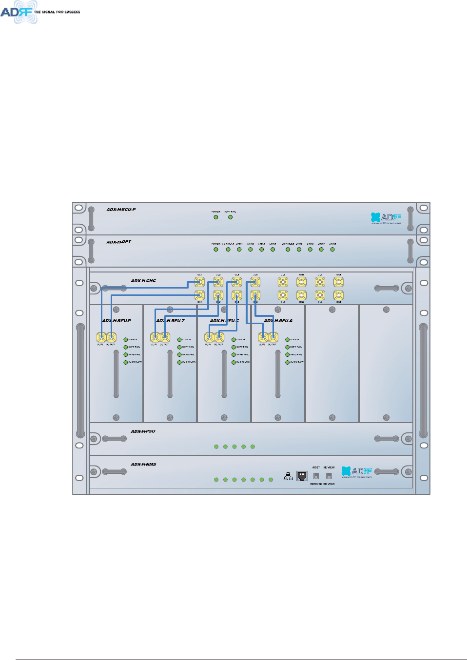
Figure 3-1 Head End Front View ...........................................................................................................29
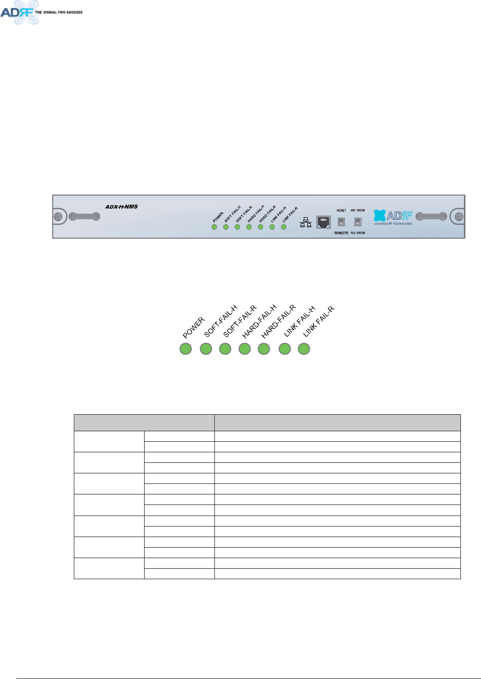
Figure 3-2 ADX-H-NMS Front View.......................................................................................................30
Figure 3-3 NMS LED .............................................................................................................................30
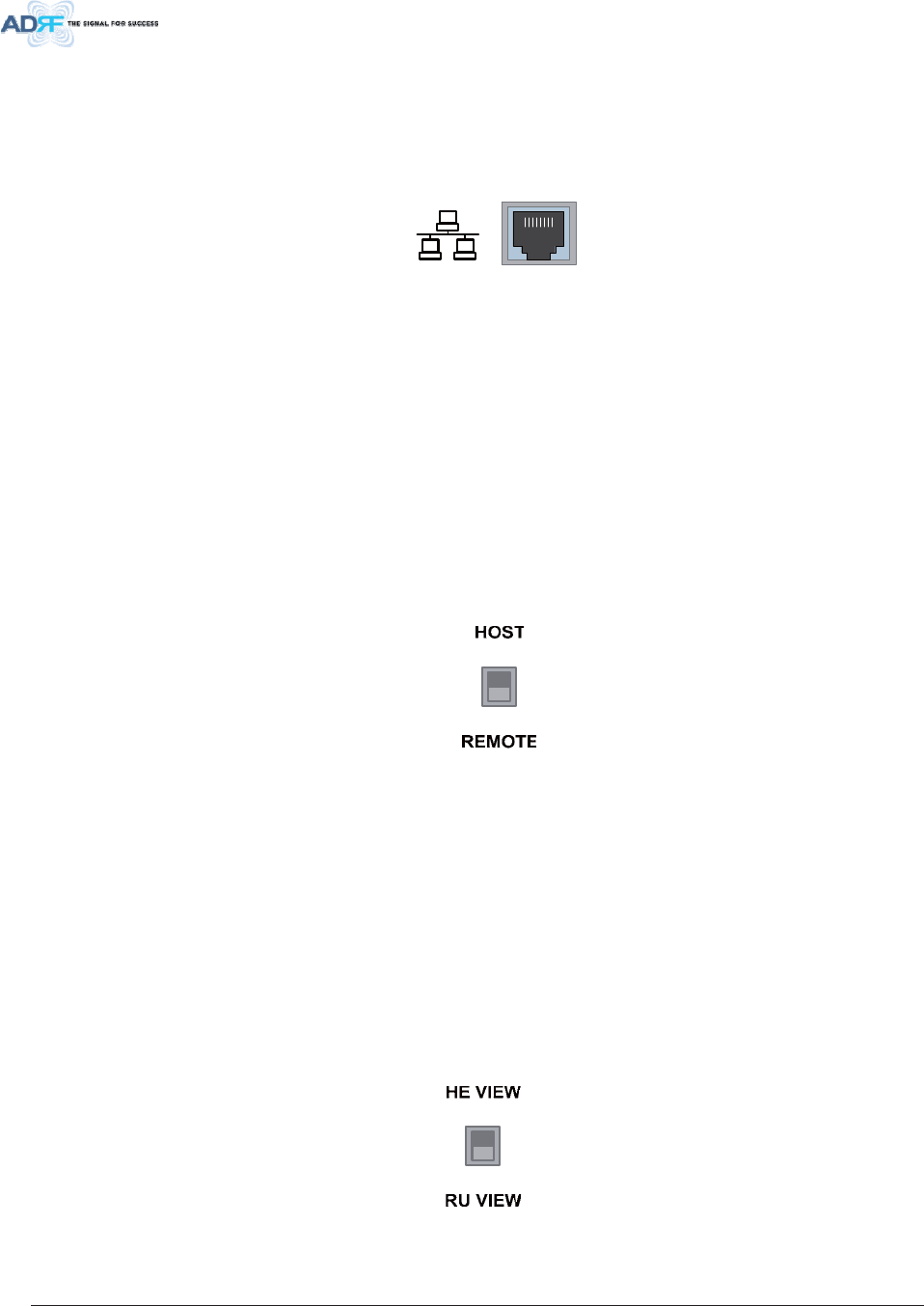
Figure 3-4 Ethernet Port ........................................................................................................................ 31
Figure 3-5 Host/Remote Switch.............................................................................................................31
Figure 3-6 HE View/RU View Switch.....................................................................................................31
Figure 3-7 RFU Front & Rear View........................................................................................................32
Figure 3-8 RFU LED .............................................................................................................................. 32
Figure 3-9 Communication Port (RFU)..................................................................................................33
Figure 3-10 ADX-H-CHC Front & Rear View........................................................................................... 33
Figure 3-11 ADX-H-OPT Front & Rear View ...........................................................................................34
Figure 3-12 OPT LED ..............................................................................................................................34
Figure 3-13 OPT RF Ports....................................................................................................................... 34
Figure 3-14 OPT Optic Ports ................................................................................................................... 35
Figure 3-15 Communication Port (OPT)..................................................................................................35
Figure 3-16 ADX-H-PSU Front & Rear View ...........................................................................................35
Figure 3-17 HE PSU LED ........................................................................................................................35
Figure 3-18 HE PSU AC Input On/Off Switch, AC Input Port and AC Input Selection Switch ................36
Figure 3-19 Battery Backup Port, Battery Install Port and Battery Backup Switch ................................. 36
Figure 3-20 ADX-H-BCU Front & Rear View...........................................................................................37
Figure 3-21 BCU LED.............................................................................................................................. 37
Figure 3-22 Communication Port (BCU)..................................................................................................38
Figure 3-23 ADX-H-OEU Front & Rear View...........................................................................................38

Advanced RF Technologies, Inc. ix
Figure 3-24 OPT LED ..............................................................................................................................38
Figure 3-25 OEU Optic Ports................................................................................................................... 39
Figure 3-26 DC Power Input Port & GUI Port..........................................................................................39
Figure 3-27 Power On/Off Switch & ADDR .............................................................................................39
Figure 3-28 OEU Block Diagram .............................................................................................................40
Figure 3-29 RU Front View ......................................................................................................................41
Figure 3-30 RU Rear View.......................................................................................................................41
Figure 3-31 Master RU Front & Rear View..............................................................................................42
Figure 3-32 Master RU LED ....................................................................................................................42
Figure 3-33 RF Ports (Master RU)...........................................................................................................43
Figure 3-34 Master RU block Diagram and RF Port Name.....................................................................43
Figure 3-35 Ports at the back panel (Master RU)....................................................................................44
Figure 3-36 Correct RS-485 connection between Master RU and Slave RU or between Slave RUs ....45
Figure 3-37 Wrong RS-485 connection between Master RU and Slave RU or between Slave RUs......45
Figure 3-38 Do NOT connect RS-485 ports of Sub RU to network equipment port................................45
Figure 3-39 Slave RU Front & Rear View................................................................................................46
Figure 3-40 Slave RU LED ...................................................................................................................... 46
Figure 3-41 RF Ports (Slave RU).............................................................................................................47
Figure 3-42 Slave RU block Diagram and RF Port Name.......................................................................47
Figure 3-43 Ports at the rear panel (Slave RU) .......................................................................................47
Figure 3-44 RU PSU Front & Rear View .................................................................................................48
Figure 3-45 RU PSU LED........................................................................................................................48
Figure 3-46 RU PSU Power Switch View ................................................................................................49
Figure 3-47 Battery Backup Port & Battery Backup Switch.....................................................................49
Figure 3-48 DC Output Port (RU PSU)....................................................................................................50
Figure 3-49 PSU Alarm Port (RU PSU)...................................................................................................50
Figure 3-50 ADX-R-4WS Front View.......................................................................................................50
Figure 3-51 ADX-R-4WS Inner View .......................................................................................................50
Figure 4-1 HE Cable connection (1 OPT+1 BCU).................................................................................51
Figure 4-2 HE Cable connection (4 OPTs)............................................................................................52
Figure 4-3 RU Cable connection (4 Sub RU + RU PSU) ......................................................................53
Figure 4-4 Slave RU Expansion using ADX-R-4WS .............................................................................54
Figure 5-1 HE Rack Mount (Front & Rear view)....................................................................................55
Figure 5-2 HE Wall Mount (Top View)...................................................................................................56
Figure 5-3 RU Rack Mount (Front view)................................................................................................57
Figure 5-4 19” Shelf type - RU Wall Mount (Top view)..........................................................................58
Figure 5-5 Sub RU Wall Mount (Top view)............................................................................................58
Figure 6-1 ADX HE 19” Rack Mount Instructions ..................................................................................60
Figure 6-2 ADX HE Wall Mount Instructions .........................................................................................62
Figure 6-3 Wall Mount Instructions for ADX-HE added 1U Unit............................................................63
Figure 6-4 ADX-RU 19” Rack Mount Instructions..................................................................................65
Figure 6-5 ADX-RU Wall Mount Instructions .........................................................................................67
Figure 6-6 Wall Mount Instructions for ADX-RU added 1.5U Unit.........................................................68
Figure 6-7 Sub RU Wall Mount Instructions ..........................................................................................69
Figure 6-8 ADX-H-OEU Rack Mount Instructions ................................................................................. 71
Figure 6-9 ADX-H-OEU Wall Mount Instructions...................................................................................72
Figure 6-10 Ground Cable Connection (HE rear side) ............................................................................73
Figure 6-11 Ground Cable Connection (RU rear side) ............................................................................73
Figure 6-12 Optic Connector Cleaning (left) and Optic Port Cleaning (right)..........................................74
Figure 6-13 SC/APC Optic Connector Dust Cap.....................................................................................74
Figure 7-1 Login window........................................................................................................................75
Figure 7-2 Navigation tree Lock/Unlock ................................................................................................76
Figure 7-3 Navigation tree .....................................................................................................................76
Figure 7-4 OPT Install page................................................................................................................... 78
Figure 7-5 measured optic loss display .................................................................................................78
Figure 7-6 BCU Install Window.............................................................................................................. 80

Advanced RF Technologies, Inc. x
Figure 7-7 RFU Install Window.............................................................................................................. 81
Figure 7-8 Sub RU Install Window.........................................................................................................82
Figure 8-1 Login screen......................................................................................................................... 87
Figure 8-2 Navigation tree Lock/Unlock ................................................................................................89
Figure 8-3 Navigation tree .....................................................................................................................89
Figure 8-4 ADX DAS General Information.............................................................................................90
Figure 8-5 Status - NMS ........................................................................................................................92
Figure 8-6 System Summary .................................................................................................................92
Figure 8-7 System scan time, HE view/RU view ...................................................................................93
Figure 8-8 HE alarm status.................................................................................................................... 93
Figure 8-9 HE Commissioning status ....................................................................................................94
Figure 8-10 Status – RFU........................................................................................................................95
Figure 8-11 Power & Gain Display (Admin).............................................................................................96
Figure 8-12 Power & Gain Display (User) ...............................................................................................96
Figure 8-13 Status - OPT.........................................................................................................................97
Figure 8-14 Summary (Status – OPT) .....................................................................................................98
Figure 8-15 RF Status (Status – OPT) ....................................................................................................98
Figure 8-16 Optic Status (Status – OPT).................................................................................................98
Figure 8-17 Optic Attenuation (Status – OPT).........................................................................................99
Figure 8-18 Optic Path Status (Status – OPT) ........................................................................................99
Figure 8-19 Status - RU Hub ................................................................................................................. 100
Figure 8-20 RU Alarm Status (Status - RU Hub)...................................................................................100
Figure 8-21 RU Commissioning Status (Status - RU Hub)....................................................................100
Figure 8-22 Status – Sub RU.................................................................................................................101
Figure 8-23 PCS Band Information (Status – Sub RU) .........................................................................102
Figure 8-24 Power & Gain (Admin)........................................................................................................102
Figure 8-25 Power & Gain (User) ..........................................................................................................102
Figure 8-26 Optic Power (Status – Master RU only) .............................................................................103
Figure 8-27 Control - NMS..................................................................................................................... 104
Figure 8-28 Heartbeat (Control – NMS).................................................................................................104
Figure 8-29 HE System Reboot & Factory Setting (Control – NMS).....................................................104
Figure 8-30 NMS System Reboot & Factory Setting (Control – NMS)..................................................104
Figure 8-31 Control - RFU .....................................................................................................................105
Figure 8-32 General Setting (Control – RFU) (Admin) ..........................................................................105
Figure 8-33 General Setting (Control – RFU) (User).............................................................................105
Figure 8-34 Reboot & Factory Setting (Control – RFU).........................................................................106
Figure 8-35 UL Noise Detection (Control – RFU)..................................................................................106
Figure 8-36 UL Noise Detection - PCS band.........................................................................................106
Figure 8-37 Manual Attenuator Control Setting (Control – RFU) ..........................................................107
Figure 8-38 Alarm Threshold Setting (Control – RFU) ..........................................................................107
Figure 8-39 Control – OPT .................................................................................................................... 108
Figure 8-40 Optic Attenuation – OPT ....................................................................................................109
Figure 8-41 Reboot & factory Setting (Control – OPT)..........................................................................109
Figure 8-42 Control – RU Hub ...............................................................................................................110
Figure 8-43 Reboot & factory Setting (Control – RU Hub) ....................................................................110
Figure 8-44 Control – Sub RU ...............................................................................................................111
Figure 8-45 General Setting (Control - RU)..........................................................................................111
Figure 8-46 Reboot & factory Setting (Control - RU).............................................................................112
Figure 8-47 Optic Setting (Control - RU) ...............................................................................................112
Figure 8-48 Manual Atten Control (Control - RU) ..................................................................................112
Figure 8-49 Alarm Setting (Control - RU) ..............................................................................................113
Figure 8-50 Install - NMS.......................................................................................................................114
Figure 8-51 HE Commissioning Status (Install – NMS).........................................................................114
Figure 8-52 SNMP (Install – NMS) ........................................................................................................115
Figure 8-53 Location Setting (Install – NMS).........................................................................................115
Figure 8-54 External Modem Box Setting (Install – NMS).....................................................................115

Advanced RF Technologies, Inc. xi
Figure 8-55 Description (Install – NMS).................................................................................................116
Figure 8-56 SNMP Agent Flase Alarm Test (Install – NMS) .................................................................116
Figure 8-57 Location Info / Installer Info (Install – NMS) .......................................................................116
Figure 8-58 Date & Time Setting (Install – NMS) ..................................................................................117
Figure 8-59 Install - RFU .......................................................................................................................117
Figure 8-60 RFU Commissioning (Install – RFU) ..................................................................................118
Figure 8-61 Description (Install – RFU) .................................................................................................118
Figure 8-62 Install – OPT.......................................................................................................................119
Figure 8-63 Optic control (Control – OPT).............................................................................................119
Figure 8-64 Description (Install – OPT) .................................................................................................120
Figure 8-65 Install-RU Hub ....................................................................................................................120
Figure 8-66 RU Commissioning Status (Install-RU Hub) ......................................................................120
Figure 8-67 Description (Install-RU Hub) ..............................................................................................121
Figure 8-68 Install-Sub RU .................................................................................................................... 121
Figure 8-69 RU Output Commissioning (Install-RU) .............................................................................121
Figure 8-70 Description (Install-Sub RU)...............................................................................................122
Figure 8-71 Account Management ........................................................................................................122
Figure 8-72 New Account ...................................................................................................................... 122
Figure 8-73 Change Password ..............................................................................................................123
Figure 8-74 Event Log ...........................................................................................................................123
Figure 8-75 User Log............................................................................................................................. 124
Figure 8-76 System update ...................................................................................................................124
Figure 8-77 Message after System update is complete ........................................................................125
Figure 8-78 System Information ............................................................................................................125
Figure 8-79 System Notification............................................................................................................. 126
Figure 8-80 Bill of material..................................................................................................................... 126
Figure 8-81 Setting Backup (Before) .....................................................................................................127
Figure 8-82 Setting Backup (After) .........................................................................................................127
Figure 8-83 Setting Restore...................................................................................................................128
Figure 8-84 SNMP V1/V2 ...................................................................................................................... 128
Figure 8-85 SNMP V3............................................................................................................................ 129
Figure 8-86 System- Closeout Package................................................................................................129
Figure 8-87 System- Closeout Package after the file upload ................................................................129
Figure 8-88 Help .................................................................................................................................... 130
Figure 10-1 HE Drawing ........................................................................................................................132
Figure 10-2 Master RU Drawing............................................................................................................133
Figure 10-3 Slave RU Drawing ..............................................................................................................134
Figure 10-4 RU Rack Shelf Drawing......................................................................................................135

Advanced RF Technologies, Inc. xii
Tables
Table 1-1 HE Parts List ........................................................................................................................ 15
Table 1-2 RU Parts List ........................................................................................................................18
Table 2-1 ADX-DAS Scalability ............................................................................................................28
Table 3-1 NMS LED Specifications ......................................................................................................30
Table 3-2 RFU LED Specifications.......................................................................................................32
Table 3-3 OPT LED Specifications.......................................................................................................34
Table 3-5 HE PSU LED Specifications.................................................................................................36
Table 3-4 BCU LED Specifications.......................................................................................................37
Table 3-6 OPT LED Specifications.......................................................................................................38
Table 3-7 Master RU LED Specifications.............................................................................................42
Table 3-8 Slave RU LED Specifications...............................................................................................46
Table 3-9 RU PSU LED Specifications................................................................................................. 48
Table 7-1 Optic loss compensation table .............................................................................................79
Table 7-2 Back-off value for each technology due to traffic breathing.................................................83
Table 7-3 Input signal conditions @HE RFU downlink input................................................................84
Table 7-4 HE maximum downlink input level without 10dB attenuator ................................................84
Table 7-5 HE downlink input signal conditions after adding 10dB attenuator to HE downlink input port
85
Table 7-6 HE maximum downlink input level after adding 10dB attenuator to HE downlink input port85
Table 7-7 Input signal conditions @HE BCU downlink input ...............................................................85
Table 7-8 HE maximum downlink input level .......................................................................................85
Table 7-9 Targeted maximum input power...........................................................................................86
Table 7-10 Maximum Output Power per carrier .....................................................................................86
Table 9-1 Account Information for Login ..............................................................................................88
Table 9-2 Navigation tree ..................................................................................................................... 89
Table 9-3 Power Supply Status............................................................................................................90
Table 9-4 Commissioning ICON...........................................................................................................90
Table 9-5 System Summary Description..............................................................................................93
Table 9-6 Description for HE Commissioning status............................................................................94
Table 9-7 Description for NMS alarm ...................................................................................................94
Table 9-8 Band Information (Status-RFU)............................................................................................95
Table 9-9 RFU Alarm Status ................................................................................................................ 96
Table 9-10 Summary Description ...........................................................................................................98
Table 9-11 Description for optic path status...........................................................................................99
Table 9-12 Description for RU Commissioning status..........................................................................100
Table 9-13 Alarm Status (Status - RU Hub) .........................................................................................101
Table 9-14 Operating Status (Status – Sub RU) ..................................................................................103
Table 9-15 Description for General Setting ..........................................................................................105
Table 9-16 Description for Main Gain Control Setting (Control – RFU) ...............................................107
Table 9-17 Description for Alarm Threshold Setting (Control – RFU)..................................................107
Table 9-17 Description for Optic Attenuation (Control – OPT).............................................................109
Table 9-18 Description for General Setting (Control - RU) ..................................................................111
Table 9-19 Description for Optic Setting (Control - RU) .......................................................................112
Table 9-20 Description for Manual Atten Control (Control - RU)..........................................................112
Table 9-21 Description for HE Commissioning Status (Install – NMS) ................................................114
Table 9-22 Description for Optic control (Control – OPT) ....................................................................119
Table 9-12 Description for RU Commissioning status..........................................................................120

Advanced RF Technologies, Inc. xiii
Terms and Abbreviations
The following is a list of abbreviations and terms used throughout this document.
$EEUHYLDWLRQ7HUP 'HILQLWLRQ
$*& Automatic Gain Control
$/& Automatic Level Control
$5206 ADRF’ Repeater Operation and Management System
%&8 Band Combiner Unit
%76 Base Transceiver Station
&'0$ Code Division Multiple Access
&+& Channel combiner
&: Continuous Wave (un-modulated signal)
'$6 Distributed Antenna System
'/ Downlink
'RZQOLQN The path covered from the Base Transceiver Station (BTS) to the subscribers’
service area via the repeater
+( Head End
+3$ High Power Amplifier
+: Hardware
,) Intermediate Frequency
/1$ Low Noise Amplifier
/7( Long Term Evolution
06 Mobile Station
106 Network Management System
2'8 Optic Donor Unit which is located in OPT. A OPT has two ODUs.
2(8 Optic Expansion Unit
237 Optic Unit
3// Phased Locked Loop
368 Power Supply Unit
5) Radio Frequency
5)8 RF Channel Unit
58 Remote Unit which is composed of master RU and multiple slaves RU
64( Signal Quality Estimate
6XE58 generic term for master RU and slave RU
6: Software
8/ Uplink
8SOLQN The path covered from the subscribers’ service area to the Base Transceiver
Station (BTS) via the repeater
96:5 Voltage Standing Wave Ratio

Advanced RF Technologies, Inc. 14
,1 752'8&7,21
8SWRIUHTXHQF\EDQGVLQRQHERG\: Currently the ADX supports 700 MHz (Lower A, Lower B,
Upper C), Cellular, PCS, and AWS bands.
+ LJKOLJKWV
x Modular Structure
- Supports multi bands service (700MHz, Cell, PCS, AWS, etc.) in one body
- Can support up to 8 RF units
x Supports optional combining/balancing of multiple carriers’ signals via BCU (Band Combiner Unit)
x MIMO capable
x Supports up to a of maximum of 32 Remote Units
x 30dBm of downlink composite output power
x Operates with up to 5dBo optical loss (Single mode)
x Supports SNMP v1, v2, v3 (get, set & traps)
x Web-based GUI Interface; No 3rd party GUI software required
x Web-GUI connectivity via DHCP in host mode
x Versatility and Usability: ADX gives total control to the user. Control parameters such as gain,
output power, and alarm threshold can be changed using Web-GUI interface allowing the user to fine
tune the system to the given RF environment.
x Automatic uplink noise measurement routine
x Automated installation
x Support RU View mode, refer to section 3.1.1.4
x Incremental Automatic Shutdown/Resume Time: ADX gradually increases the time span between
automatic shutdown and resume period before it permanently shuts itself down
x Support ALC function to prevent ADX DAS from input overload or output overpower

Advanced RF Technologies, Inc. 15
3DUW V/LVW
+(3DUW/LVWV
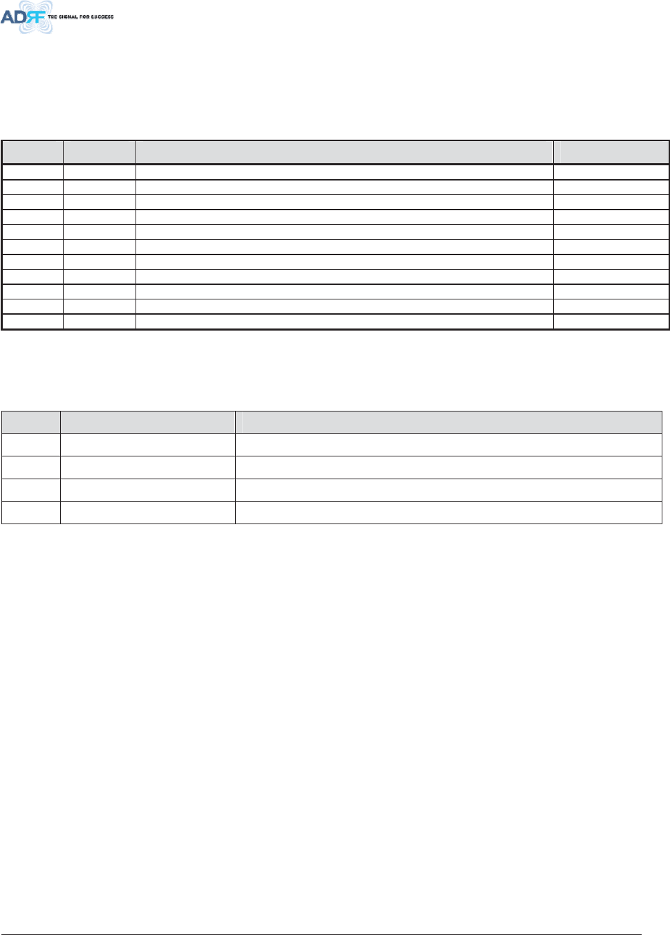
7DEOH +(3DUWV/LVW
/DEHO 4XDQWLW\ 'HVFULSWLRQ
$';+1065HTXLUHG
A 1 ADX-H-NMS (NMS module)
B 1 HE Chassis
R 1 Extension bracket for added modules, wall mount
C 1 AC Power Cable
D 1 Ethernet Cable (Crossover)
E 1 Ground Cable
F 8 Anchor Bolt
G 1 Documentation CD(User Manual, Quick Start Guide and Troubleshooting
Guide)
$';+5)8V$WOHDVWUHTXLUHG
H Up to 8 ADX-H-RFU, At least 1 module must be present in order to use ADX DAS
I 2/RFU RF Cables between CHC and RFU, SMA Male to SMA Male
M 1/RFU Module Data Cable, needed for RFUs connected to AUX CH1 or 2 ports
$';+&+&5HTXLUHG
J 1 ADX-H-CHC (HE Channel Combiner)
$';+3685HTXLUHG
J 1 ADX-H-PSU (HE Power Supply Unit)
C 1 AC Cable
$';+237RU$';+2'8$WOHDVWUHTXLUHG
K 1 ADX-H-OPT or ADX-H-ODU
L 2 or 4 RF Cables between CHC and OPT, SMA Male to SMA Male
4 for ADX-H-OPT/ 2 for ADX-H-ODU
M 1 Module Data Cable
S 1 Extension bracket for wall mount
$';+%&82SWLRQDO
N 1 Optional Band Combiner
O 2 RF Cables between BCU and RFU, N Male to N Male
M 1 Module Data Cable
S 1 1U Extension bracket for wall mount
$';+2(82SWLRQDO
P 1 ADX-H-OEU (Optic Expansion Unit)
Q 1 AC/DC Adaptor
C 1 AC Cable
Advanced RF Technologies, Inc. 16
ADX-H-NMS
32:(5
62)7)$,/+
62)7)$,/5
+$5')$,/+
+$5')$,/5
/,1.)$,/+
/,1.)$,/5
+267 +(9,(:
5(027( 589,(:
ADX-H-PSU
32:(5
&+*676
/2:%$77
$&)$,/
'&)$,/
'/2878/,1
+$5')$,/
'/6,*/2:
62)7)$ ,/
32:(5
ADX-H-RFU-P
'/2878/,1
+$5')$,/
'/6,*/2:
62)7)$,/
32:(5
ADX-H-RFU- 7
'/2878/,1
+$5')$,/
'/6,*/2:
62)7)$ ,/
32:(5
ADX-H-RFU- C
'/2878/,1
+$5')$,/
'/6,*/2:
62)7)$,/
32:(5
ADX-H-RFU-A
ADX-H-CHC
8/ 8/ 8/ 8/
'/ '/ '/ '/
8/ 8/ 8/ 8/
'/ '/ '/ '/
/')$,/ /,1. /,1. /,1. /,1./')$,/ /,1. /,1. /,1. /,1.32:(5
ADX-H-OPT
62)7)$ ,/32:(5
ADX-H-BCU-P
)LJXUH +(3DUWV/LVW
B
A
C D E F G
H
I
J
K
N
P
J
L M O Q
R S

Advanced RF Technologies, Inc. 17

Advanced RF Technologies, Inc. 18
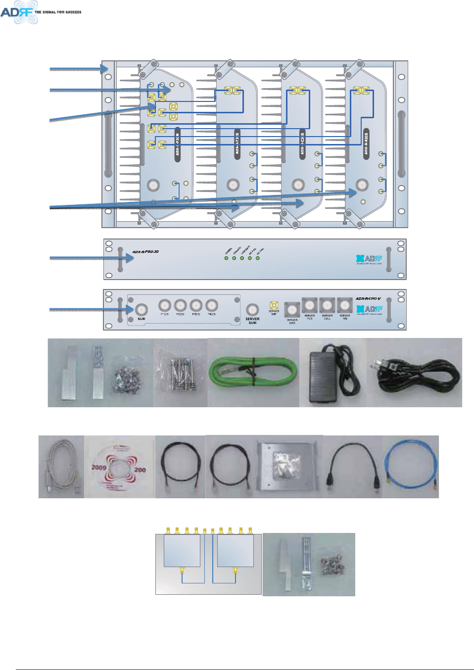
5 83DUW/LVWV
7DEOH 583DUWV/LVW
/DEHO 4XDQWLW\ 'HVFULSWLRQ
$';5&+$2SWLRQDO
A 1 ADX-R-CHA-30 (RU Chassis) – Supports (1) Master RU + (3) Slave RU
B 1 Extension bracket for added modules, wall mount
C 1 Anchor Bolt
D 1 Ground Cable
0DVWHU58$WOHDVWUHTXLUHG
E 1 ADX-R-x30M (Master RU)
H 1 USB Cable (Type A to Type B)
I 1 Documentation CD(User Manual, Quick Star Guide and Troubleshooting
Guide)
J 1 Power Cable connected to RU PSU
K 1 PSU Alarm Cable connected to RU PSU
L 1 Wall Mount Bracket & Bolt
6ODYH582SWLRQDO
M Up to 7 ADX-R-x30S (Slave RU)
N 2 RF cables between Mater RU and Slave RU
O 1 RS 485 Cable
J 1 Power Cable connected to RU PSU
L 1 Wall Mount Bracket & Bolt
$';5:62SWLRQDO
P 1 4W splitter to support more than 4 Sub RUs
Q 2 RF cables between Mater RU and ADX-R-4WS
$';53685HTXLUHGRUFDQXVH$';5$'3
R 1 ADX-R-PSU-30 (Power Supply Unit)
S 1 1.5U Extension bracket for wall mount
$';5&+&92SWLRQDO
T 1 ADX-R-CHC-V (RU channel combiner for VZW)
S 1 1.5U Extension bracket for wall mount
$';5$'35HTXLUHGRUFDQXVH$';5368
F 1 AC/DC Adaptor
G 1 AC Cable
Advanced RF Technologies, Inc. 19
DL IN
SERVER
CPL(-30dB)
UL OUT
EF-DL OUT EF-DL IN EF-UL IN EF-UL OUT
DL IN
SERVER
CPL(-30dB)
UL OUT
EF-DL OUT EF-DL IN EF-UL IN EF-UL OUT
DL IN
SERVER
CPL(-30dB)
UL OUT
EF-DL OUT EF-DL IN EF-UL IN EF-UL OUT
SERVER
UL4 UL3 UL2 UL1
DL4 DL3 DL2 DL1 M-DL
M-UL
CPL(- 30dB)
E-DL
E-UL
VHF DL VHF UL
EF-DL IN EF-DL OUT
EF-UL INEF-UL OUT
)LJXUH 583DUWV/LVW
A
BCD
E
F G
H I JKLO Q
M
N
R
P S
T
Advanced RF Technologies, Inc. 20
32:(5
62)7)$,/+
62)7)$,/5
+$5')$,/+
+$5')$,/5
/,1.)$,/+
/,1.)$,/5
32:(5
&+*676
/2:%$77
$&)$,/
'&)$,/
9+)8/ 8/287 9+)'/ '/,1
/,1. /,1. /,1. /,1.
9+)8/ 8/287 9+)'/ '/,1
/,1. /,1. /,1 . /,1.
237
'/,1 8/287
'3;
'/,1 8/287
'3;
'/,1 8/287
'3;
'/,1 8/287
'3;
8/8/ 8/8/
'/'/ '/'/
8/8/ 8/8/
'/'/ '/'/
237 237
237 237
%$1'&20 %$1'&20
%$1'&20 %$1'&20
$8;B&+
$8;B&+
'/,1
%$1'&20
CH3 CH2 CH1 SUM
'3; 8/287 '/,1 '3; 8/287 '/,1 '3; 8/287 '/287 8/,1
BATTERY
INSTALL
BATTERY
BATTERY
AC SELECT OFF/ONAC IN
OFF
S/WOFF ON
24V 1A
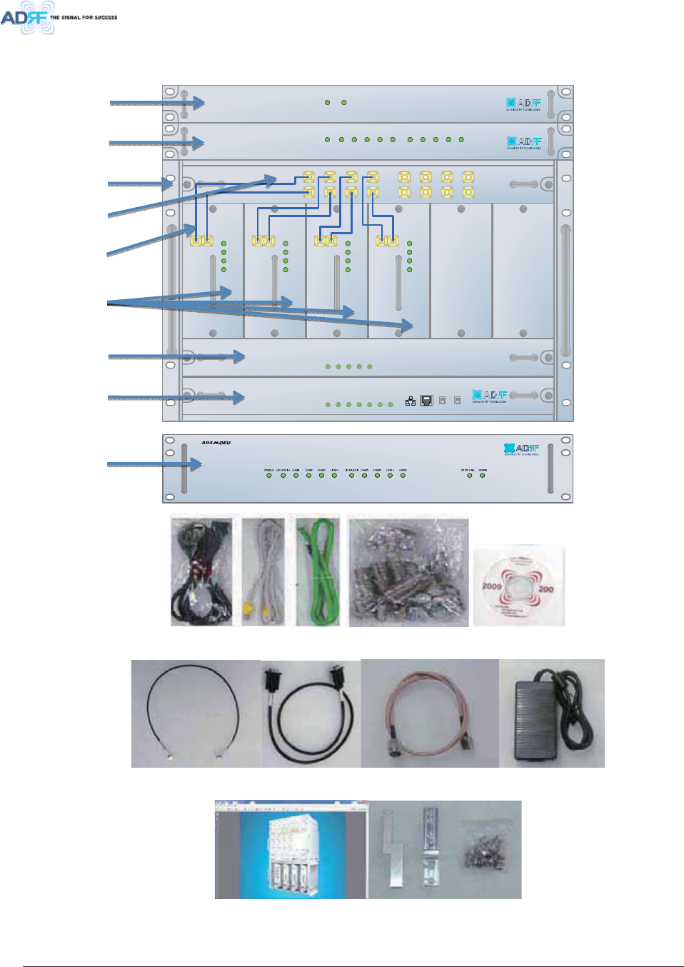
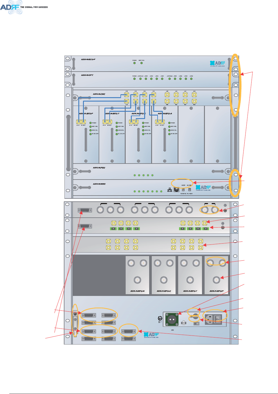
$';'$64XLFN9LHZ
+(4XLFN9LHZ
19” rack mount
Holes
Host / Remote Switch,
HE view/RU view
Switch
&RJ
45
t
Optic Ports
Battery Backup
Port
RFU Duplex
Port
A
C Input &
On/Off Switch
BCU Interface Ports
Band Combiner Unit
(BCU)
Optic Unit (OPT)
Channel Combine
r
(CHC)
RF Channel Unit
(RFU)
Power Supply Unit
(PSU)
NMS Unit
3&6 0 &HOOXODU $:6
Battery Backup
On/Off Switch
A
C Input
Voltage
Selection
Switch
(110V/220V)
RFU Simplex
Port
OPT Interface Ports
A
UX CH
Interface Ports
RF Ports
connected to
OPT
RF Ports
connected to
CHC
BCU Sum Port
)LJXUH $';'$6+(4XLFN9LHZ
Ground terminal
Advanced RF Technologies, Inc. 21
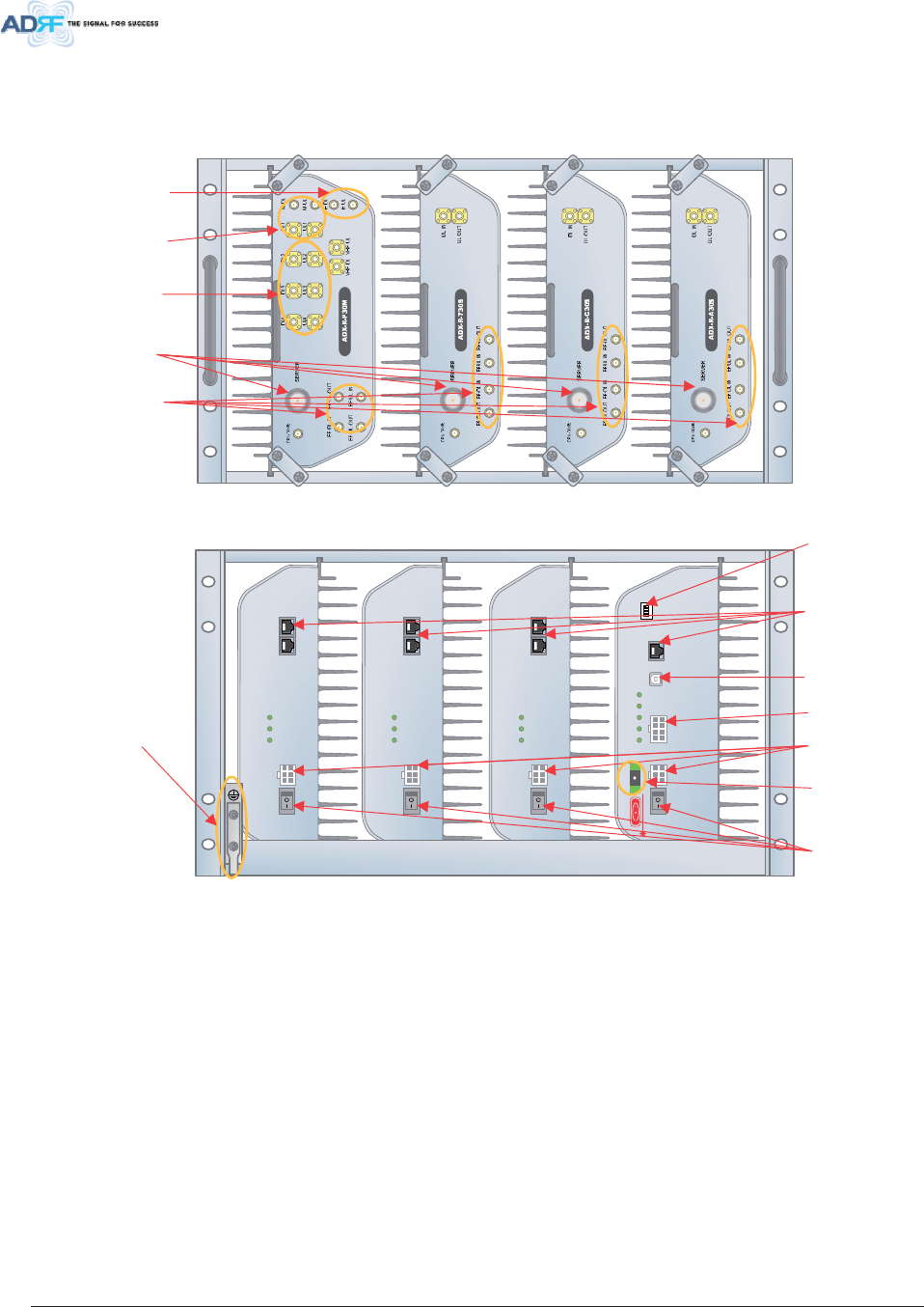
DC IN +27VON/OFF
OUT
POWER
SOFT FAIL
HARD FAIL
IN
DC IN +27VON/OFF
OUT
POWER
SOFT FAIL
HARD FAIL
IN
DC IN +27VON/OFF
OUT
POWER
SOFT FAIL
HARD FAIL
IN
POWER
SOFT FAIL
HARD FAIL
COMM
OPTICF
AIL
DC IN +27V PSU ALARM RS-485GUI
OPTIC
ON/OFF
ON
ADDR
584XLFN9LHZ
)LJXUH $';'$6584XLFN9LHZ
Server Antenna Port
Ports for adding External
Filter, if needed
Power On/Off
Switch
Expansion RF ports
to support additional
(4) slave RU.
0DVWHU
58
6ODYH58 6ODYH58 6ODYH58
DC Input Ports
Optic Port
Port for receiving Alarm
Status of RU PSU
GUI Access Port
Communication port
between Master RU and
Slave RU (RS-485
interface)
Dip Switch for Master
A
ddress Setting
ll
Ground terminal
RF ports connected to
Slave RUs in same
chassis.
RF ports for Master RU
connection.
Advanced RF Technologies, Inc. 22
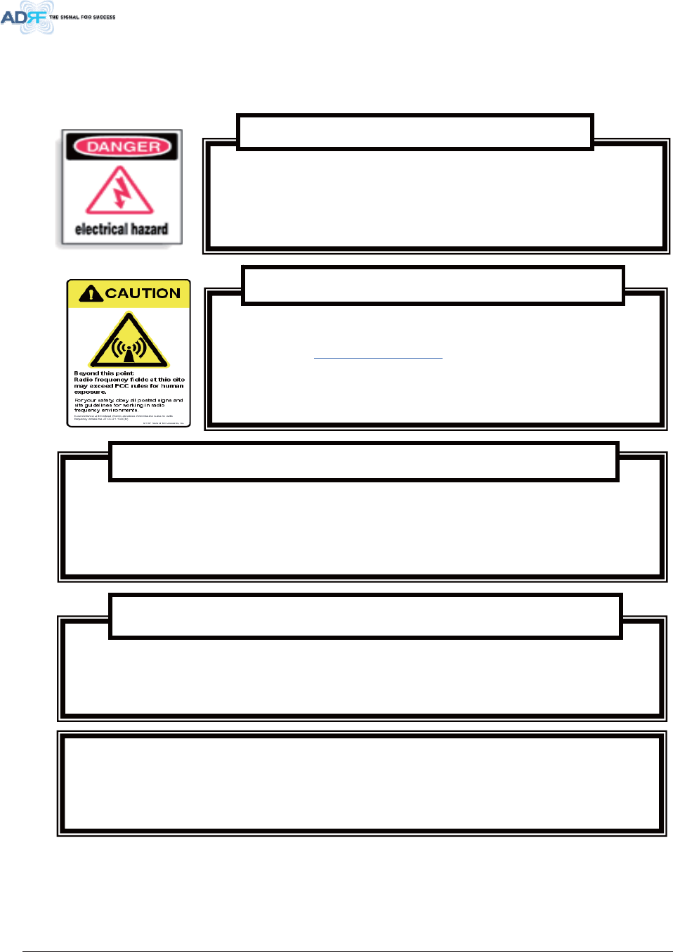
: DUQLQJVDQG+D]DUGV
/LWKLXP%DW WHU\ &$87,215,6 .2)(;3/2 6,21,)% $77(5<,6 5(3/$&('%<
,1&255(&77<3(',6326(2)86('%$77(5,(6$&&25',1*72,16758&7,216
2SHQLQJRUWDPSHULQJWKH$';'$6ZLOOYRLGDOOZDUUDQWLHV
:$55$17<
$FWXDOVHSDUDWLRQGLVWDQFHLVGHWHUPLQHGXSRQJDLQRIDQWHQQDXVHG
3OHDVHPDLQWDLQDPLQLPXPVDIHGLVWDQFHRIDWOHDVWGFPZKLOHRSHUDWLQJQHDUWKHGRQRUDQGWKHVHUYHU
DQWHQQDV$OVRWKHGRQRUDQWHQQDQHHGVWREHPRXQWHGRXWGRRUVRQDSHUPDQHQWVWUXFWXUH
5)(;32685($17(11$3/$&(0(17
*XLGHOLQHV
:RUNLQJZLWKWKH$';'$6ZKLOHLQRSHUDWLRQPD\H[SRVHWKHWHFKQLFLDQWR
5)HOHFW URPDJQHWLF ILHOGV WKDWH[FHHG)&&UXOHVIR U KXPDQH[SRV XUH 9LVLW WKH
)&&Z HEVLWH DW ZZZIFFJRYRHWUIVDIHW\ WR OH DUQPRUH DERXWWK HHIIHFW VRI
H[SRVXUHWR5)HOHFWURPDJQHWLFILHOGV
:$51,1*(;32685(725)
2SHQLQJWKH$';'$6 FRXOGUHVXOWLQ HOHFWULFVKRFNDQGPD\
FDXVHVHYHUHLQMXU\
:$51,1*(/(&75,&
62&

Advanced RF Technologies, Inc. 23
'RQRWUHPRYHWKHSURWHFWLYHFRYHUVRQWKHILEHURSWLFFRQQHFWRUVXQWLODFRQQHFWLRQLV
UHDG\WREHPDGH'RQRWOHDYHFRQQHFWRUVXQFRYHUHGZKHQQRWFRQQHFWHG
7KHWLSRI WKHI LEHUR SWLF FRQQHFWRUVVK RXOGQRW F RPHLQW RFR QWDFW ZLWK DQ\REMHF W RU
GXVW
5HIHUWRWKHFOHDQLQJSURFHGXUHIRULQIRUPDWLRQRQWKHFOHDQLQJRIWKHILEHUWLS
&DUHRI)LEHU2SWLF&RQQHFWRUV
)LEHURSWLFSRUWVRIWKH$';'$6HPLWLQYLVLEOHODVHUUDGLDWLRQDWWKHQP
ZDYHOHQJWKZLQGRZ
7RDYRLGH\HLQMXU\QHYHUORRNGLUHFWO\LQWRWKHRSWLFDOSRUWVSDWFKFRUGVRURSWLFDO
FDEOHV'RQRWVWDUHLQWREHDPRUYLHZGLUHFWO\ZLWKRSWLFDOLQVWUXPHQWV$OZD\VDVVXPH
RSWLFDORXWSXWLVRQ
2QO\WHF KQLFLDQVI DPLOLDU ZLWK ILEHU RSWLFV DIHW\SUD FWLFHV DQGS URFHGXUHVV KRXOG
SHUIRUPR SWLFDOI LEHU FRQQHFWLRQVDQG G LVFRQQHFWLRQVR I WKH $'; '$6 DQGW KH
DVVRFLDWHGFDEOHV
7KH$';'$6FRPSOLHVZLWK&)5DQGH[FHSWIRUGHYLDWLRQVSXUVXDQW
WR ODVHU QRWLFH 1R -XO\ #,(&
$PHQGPHQW -DQ
/DVHU6DIHW\
127(7KLVHTXLSPHQWKDVEHHQWHVWHGDQGIRXQGWRFRPSO\ZLWKWKHOLPLWVIRUD
&ODVV$GLJLW DOGH YLFH SXUVXDQWWRSD UW RIW KH )&& 5XOHV7 KHVH OLPLWVD UH
GHVLJQHGWR SU RYLGH UHDVRQDEOH SURWHFWLRQDJ DLQVWKDUPI XO LQWHUIHUHQFH ZKHQ WKH
HTXLSPHQW LVRSH UDWHG LQDFRPPH UFLDOHQ YLURQPHQW7KLV HTXLSPHQW JHQHUDWHV
XVHV DQG FDQ UDGLDWH UDGLRI UHTXHQF\ HQHUJ\D QGLI QRW LQV WDOOHGD QG XVHGLQ
DFFRUGDQFHZ LWKWK HLQV WUXFWLRQPDQ XDOPD\F DXVHKD UPIXOLQW HUIHUHQFHWR UDGLR
FRPPXQLFDWLRQV2SHUDWLRQRIWKLVHTXLSPHQWLQDUHVLGHQWLDODUHDLVOLNHO\WRFDXVH
KDUPIXOLQ WHUIHUHQFHLQ ZKLFK FDVHWK HXVHU ZLOOEH UHTXLUHGWRFRUUH FWW KH
LQWHUIHUHQFHDWWKHLURZQH[SHQVH
)&&3DUW&ODVV$
(WKHUQHW,QVWUXFWLRQV7KLVHTXLSPHQWLV IRULQGRRUXVHRQO\$OOFDEOLQJVKRXOGEH
OLPLWHGWRLQVLGHWKHEXLOGLQJ
Advanced RF Technologies, Inc. 24
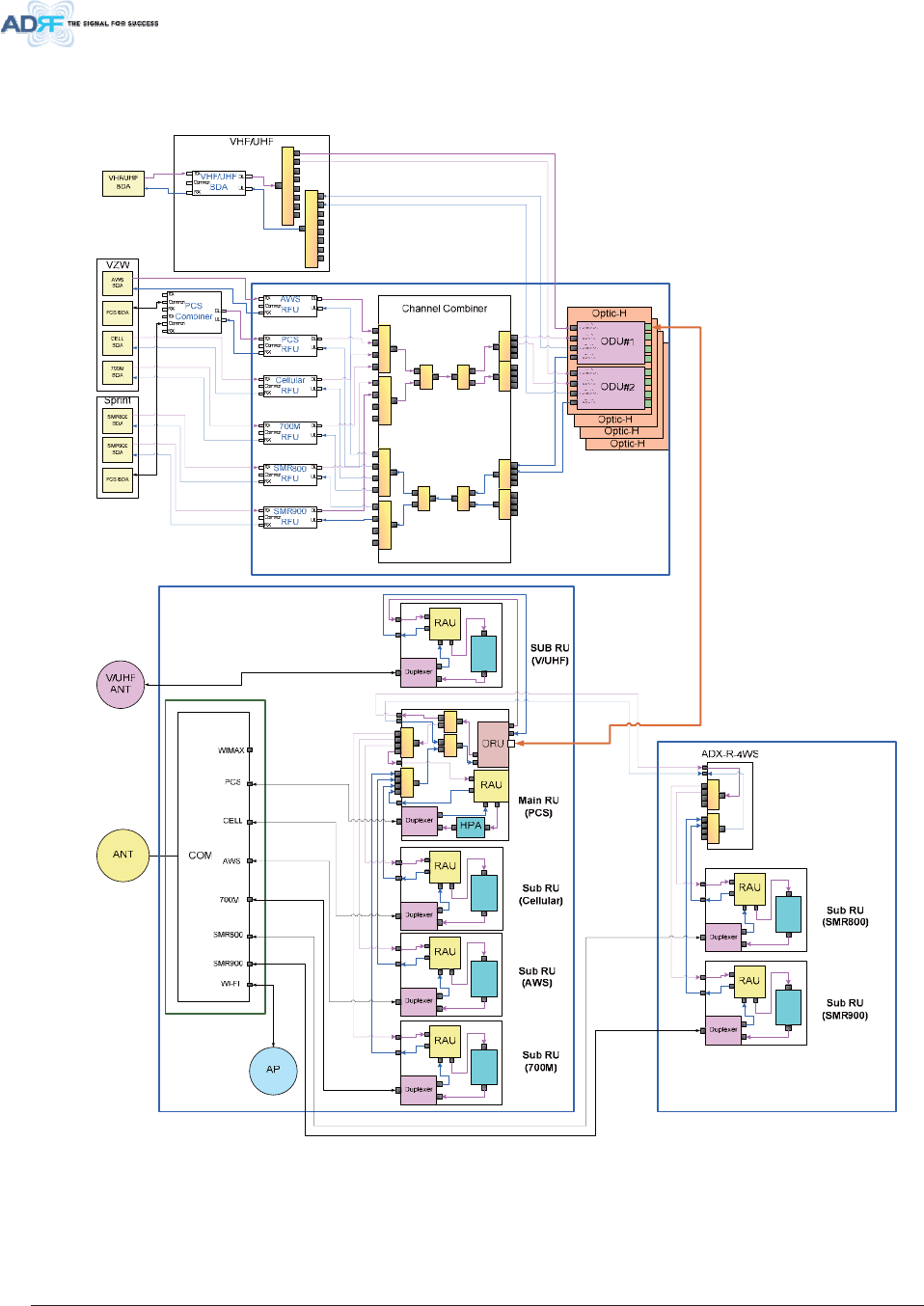
% /2&.',$*5$0
$';'$6%ORFN'LDJUDP
HPA
HPA
HPAHPA
HPA
HPA
)LJXUH $';'$6%ORFN'LDJUDP
Advanced RF Technologies, Inc. 25
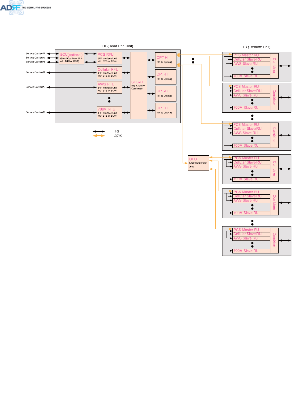
$ ';'$67RSRORJ\
)LJXUH $';'$67RSRORJ\
Advanced RF Technologies, Inc. 26
6,62 &RQILJXUDWLRQ
32:(5
&+*676
/2:%$77
$&)$,/
'&)$,/
32:(5
&+*676
/2:%$77
$&)$,/
'&)$,/
32:(5
&+*676
/2:%$77
$&)$,/
'&)$,/
32:(5
62)7)$,/+
62)7)$,/5
+$5')$,/+
+$5')$,/5
/,1.)$,/+
/,1.)$,/5
32:(5
&+*676
/2:%$77
$&)$,/
'&)$,/
)LJXUH $';'$66,62&RQILJXUDWLRQ
Advanced RF Technologies, Inc. 27
0,02 FRQILJXUDWLRQ
HE (SISO)
$';+237
$';+368
POWER
CHG STS
$';+&+&
DL 1 DL 2 DL 3 DL 4 DL 5 DL 6 DL 7 DL 8
UL 1 UL 2 UL 3 UL 4 UL 5 UL 6 UL 7 UL 8
POWER
ADX-H-RFU-P
UL_IN DL_OUT
SOFT FAIL
POWER
HARD FAIL
DL SIG LOW
ADS-H-RFU-7
UL_IN DL_OUT
SOFT FAIL
POWER
HARD FAIL
DL SIG LOW
ADX-H-RFU-C
UL_IN DL_OUT
SOFT FAIL
POWER
HARD FAIL
DL SIG LOW
ADX-H-RFU-A
UL_IN DL_OUT
SOFT FAIL
POWER
HARD FAIL
DL SIG LOW
LD FAIL 1-4 LINK1 LINK2 LINK3 LINK4 LD FAIL 5-8 LINK5 LINK6 LINK7 LINK8
LOW BATT
AC FAIL
DC FAIL
$';+106
HOST
REMOTE
POWER
SOFT-FAIL-H
HE VIEW
RU VIEW
SOFT-FAIL-R
HARD-FAIL-H
HARD-FAIL-R
LINK FAIL-H
LINK FAIL-R
700MHz
eNode-B RF
$';5&+&
$';+368
WiMAXCellularSMR800AWS700MPC S
COM WIFI
Mon
UL4 UL3 UL2 UL1
DL4 DL3 DL2 DL1 M-DL
M-UL
RU (SISO)
SERVER
VHF DL
Mon
VHF UL
E-DL
E-UL
EF-UL-IN
EF-UL-OUT
EF-DL-OUT
EF-DL-IN
DL-IN UL-OUT
EF-UL-INEF-DL-OUT EF-UL-OUTEF-DL-IN
SERVER
Mon
DL-IN UL-OUT
EF-UL-INEF-DL-OUT EF-UL-OUTEF-DL-IN
SERVER
Mon
DL-IN UL-OUT
EF-UL-INEF-DL-OUT EF-UL-OUTEF-DL-IN
POWER
CHG STS
LOWBATT
ACFAIL
DCFAIL
SMR900
700M
Cellular
PCS
AWS
Optic
Optic
Optic
Cellular
BTS
PCS
BTS
AWS
BTS
$';5&+&
$';+368
WiMAXCellularSMR800AWS700MPC S
COM WIFI
Mon
UL4UL3UL2UL1
DL4DL3DL2DL1M-DL
M-UL
SERVER
VHF DL
Mon
VHF UL
E-DL
E-UL
EF-UL-IN
EF-UL-OUT
EF-DL-OUT
EF-DL-IN
DL-IN UL-OUT
EF-UL-INEF-DL-OUT EF-UL-OUTEF-DL-IN
SERVER
Mon
DL-IN UL-OUT
EF-UL-INEF-DL-OUT EF-UL-OUTEF-DL-IN
SERVER
Mon
DL-IN UL-OUT
EF-UL-INEF-DL-OUT EF-UL-OUTEF-DL-IN
POWER
CHG STS
LOW BATT
AC FAIL
DC FAIL
SMR900
700M
Cellular
PCS
AWS
$';5&+&
$';+368
WiMAXCellularSMR800AWS700MPC S
COM WIFI
Mon
UL4 UL3 UL2 UL1
DL4 DL3 DL2 DL1 M-DL
M-UL
SERVER
VHF DL
Mon
VHF UL
E-DL
E-UL
EF-UL-IN
EF-UL-OUT
EF-DL-OUT
EF-DL-IN
DL-IN UL-OUT
EF-UL-INEF-DL-OUT EF-UL-OUTEF-D L-I N
SERVER
Mon
DL-IN UL-OUT
EF-UL-INEF-DL-OUT EF-UL-OUTEF-DL-IN
SERVER
Mon
DL-IN UL-OUT
EF-UL-INEF-DL-OUT EF-UL-OUTEF-DL-IN
POWER
CHG STS
LOW BATT
ACFAIL
DC FAIL
SMR900
700M
Cellular
PCS
AWS
HE (MIMO)
$';+237
$';+368
POWER
CHG STS
$';+&+&
DL 1 DL 2 DL 3 DL 4 DL 5 DL 6 DL 7 DL 8
UL 1 UL 2 UL 3 UL 4 UL 5 UL 6 UL 7 UL 8
POWER
ADS-H-RFU-7
UL_IN DL_OUT
SOFT FAIL
POWER
HARD FAIL
DL SIG LOW
LD FAIL 1-4 LINK1 LINK2 LINK3 LINK4 LD FAIL 5-8 LINK5 LINK6 LINK7 LINK8
LOW BATT
ACFAIL
DC FAIL
$';+106
HOST
REMOTE
POWER
SOFT-FAIL-H
HE VIEW
RU VIEW
SOFT-FAIL-R
HARD-FAIL-H
HARD-FAIL-R
LINK FAIL-H
LINK FAIL-R
700MHz
eNode-B RF
Optic
Optic
Optic
Mon
UL4UL3UL2UL1
DL4DL3DL2DL1M-DL
M-UL
VHF DL VHF UL
E-DL
E-UL
EF-UL-IN
EF-UL- OU T
EF-DL-OUT
EF-DL-IN
700M Master RU
for MIMO
700M
MIMO
Mon
UL4UL3UL2UL1
DL4DL3DL2DL1M-DL
M-UL
VHF DL VHF UL
E-DL
E-UL
EF-UL-IN
EF-UL-OUT
EF-DL-OUT
EF-DL-IN
700M Master RU
for MIMO
700M
MIMO
Mon
UL4UL3UL2UL1
DL4 DL3 DL2 DL1 M- DL
M-UL
VHF DL VHF UL
E-DL
E-UL
EF-UL-IN
EF-UL-OUT
EF-DL-OUT
EF-DL-IN
700M Master RU
for MIMO
700M
MIMO
)LJXUH$';'$60,02&RQILJXUDWLRQ
x DAS system for MIMO can be supported by separate DAS System.
x
Advanced RF Technologies, Inc. 28
$ ';'$66FDODELOLW\
7DEOH $';'$66FDODELOLW\
8QLW 6FDODELOLW\ 5HPDUNV
Current 700M, Cellular, PCS, AWS
Single Band
700M including Lower C,
SMR800/900, SMR700/800,
VHF/UHF, BRS
BRS band (TDD system) will be
supported as independent system.
Supporte
d band Future
Dual Band PCS & SMR800/900, PCS & Cellular
RFU Up to 8 up to 6: card type
7th & 8th RFU: 19” rack type
NMS 1
Channel Combiner 1
Optic Unit Up to 4
Band Combiner Unit Up to 4 To support multiple carriers
HE
Power Supply Unit 1 Capable of supplying power to 8
RFUs, 4 BCUs, 4 OPTs and NMS.
RU Up to 32
OEU Up to 4
Adaptor type 1 per Sub RU
RU
PS
U19” rack mount 1 Capable of supplying power to 8 Sub
RUs
Advanced RF Technologies, Inc. 29
$ ';29(59,(:
+ HDG(QG
HE Unit is composed of CHC-H, RFU, NMS, BCU, OPT and PSU.
ADX-HE can support up to 8 RFUs and 4 BCUs.
x Spec
- Size: 19.0 x 14.6 x 12.2 inches (482 x 370 x 311 mm)
- Weight: 83.7 lbs (38.0 Kg)@4 RFU, CHC-H, PSU and NMS
- Power Consumption: 55W@4 RFU, 1 OPT and NMS, 28W@1 RFU, 1 OPT and NMS
- Power Input: 110VAC or -48VDC(optional)
- Can support an ADRF-BBU for external battery backup solution
32:(5
62)7)$,/+
62)7)$,/5
+$5')$,/+
+$5')$,/5
/,1.)$,/+
/,1.)$,/5
32:(5
&+*676
/2:%$77
$&)$,/
'&)$,/
)LJXUH +HDG(QG)URQW9LHZ
Advanced RF Technologies, Inc. 30
1061HWZRUN0DQDJHPHQW6\VWHP
x Functions and features
- Supports full SNMP v1,v2, and v3 (get, set & trap) and web-based GUI Interface.
- Monitors alarms and status
- Provides control interfaces with all subordinate modules
- Provides overall DAS structure via the auto tree update function
x Spec
- Size: 19.0 x 12.1 x 1.7 inches (482 x 307 x 44 mm)
- Weight: 5.5 lbs (2.5 kg)
)LJXUH $';+106)URQW9LHZ
/ ('V
NMS has LEDs on the front panel as shown in Figure 3-3.
)LJXUH 106/('
7DEOH 106/('6SHFLILFDWLRQV
$';'$6106 6SHFLILFDWLRQV
Solid Green NMS power is ON Power
OFF NMS power is OFF
Solid Yellow HE Soft Fail alarm exists in the system SOFT FAIL-H
Solid Green No HE Soft Fail alarms are present in the system
Solid Yellow RU Soft Fail alarm exists in the system SOFT FAIL-R
Solid Green No RU Soft Fail alarms are present in the system
Solid Red HE Hard Fail alarm exists in the system HARD FAIL-H
Solid Green No HE Hard Fail alarms are present in the system
Solid Red RU Hard Fail alarm exists in the system HARD FAIL-R
Solid Green No RU Hard Fail alarms are present in the system
Solid Yellow HE Link Fail alarm exists in the system LINK FAIL-H
Solid Green No HE Link Fail alarms are present in the system
Solid Yellow RU Link Fail alarm exists in the system LINK FAIL-R
Solid Green No RU Link Fail alarms are present in the system
Advanced RF Technologies, Inc. 31
(WKH UQHW3RUW
The Ethernet port can be used to communicate directly with the ADX DAS using a RJ-45 crossover
cable or can also be used to connect the ADX DAS to an external modem box.
)LJXUH (WKHUQHW3RUW
+ RVW5HPRWH6ZLWFK
The Host/Remote Switch allows the user to switch the default Repeater IP, Subnet Mask, and
Gateway of the repeater to an alternative setup. These settings can be adjusting by logging into the ADX
DAS in HOST mode and configuring the settings under the Modem Box Setting section on the Install
Page of NMS.
Once the settings are set, flipping the switch to the REMOTE position will reboot NMS module with
the new alternate settings. Please note that when the NMS is set to the REMOTE position, DHCP is
disabled and the NMS will not automatically assign an IP address to any device that connects directly to
the NMS.
)LJXUH +RVW5HPRWH6ZLWFK
x Host IP: 192.168.63.1 (Fixed IP, unable to modify this IP address)
x Remote IP: 192.168.63.5 (Default IP, but can be modified in Host mode)
+(9LHZ589LHZ6ZLWFK
The HE View/RU View Switch allows the user to be able to disable periodic monitoring operated by
NMS. In the HE view mode, NMS monitors the status of all subordinate units connected to NMS
periodically but when switched to RU view the NMS does not monitor the subordinate units. When the
user goes to a RU and wants to monitor/control the HE, the user should set the NMS as RU view mode
before going to the RU. If not, there might be some data collisions between the NMS and RU, which may
prevent the user from properly monitoring or configuring the HE when at the RU. Consequently, the user
should set as HE view mode when the user is at the HE and should set as RU view mode when the user
is at the RU.
)LJXUH +(9LHZ589LHZ6ZLWFK
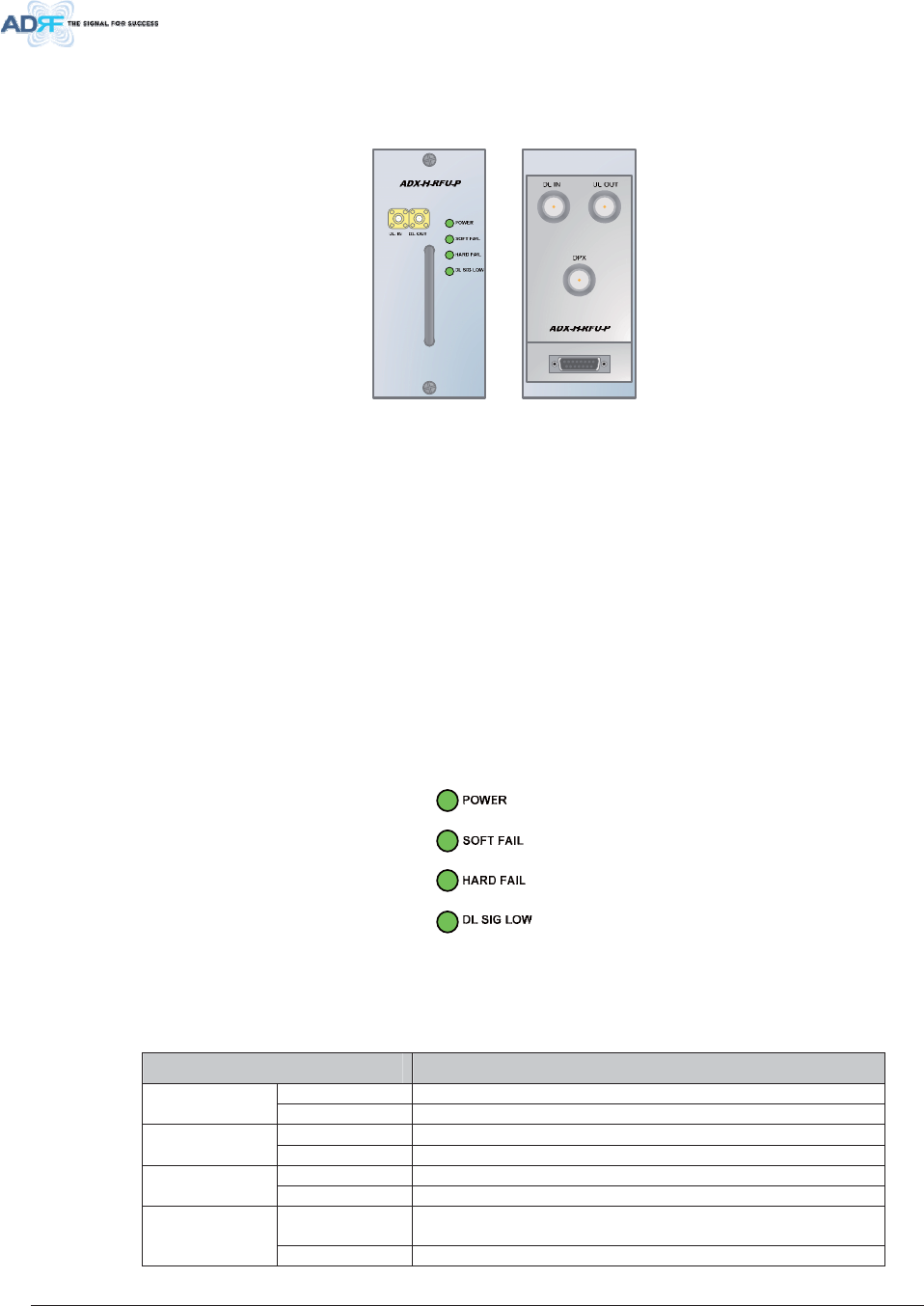
Advanced RF Technologies, Inc. 32
5 )8$';+5)8[
)LJXUH 5)8)URQW5HDU9LHZ
x Functions and features
- Provide RF interface with BTS or BDA
- Each RFU has independent gain control and filtering
- Modular type and Hot swappable
- Supports duplex port or simplex TX & RX ports
- Easily support additional frequency bands by adding a single RFU
- Reduces complexity and overall equipment size
x Spec
- Size: 12.8 x 6.2 x 2.8 inches (324 x 156.5 x 71.3 mm)
- Weight: 7.3 lbs (3.3 kg)
/ ('V
RFU has LEDs on the front panel as shown in Figure 3-8.
)LJXUH 5)8/('
7DEOH 5)8/('6SHFLILFDWLRQV
$';'$60RGXOH 6SHFLILFDWLRQV
Solid Green Module power is ON. Power
OFF Module power is OFF.
Solid Yellow Soft Fail alarm exists in the RFU. Soft Fail
Solid Green No Soft Fail alarms are present in the RFU.
Solid Red Hard Fail alarm exists in the RFU. Hard Fail
Solid Green No Hard Fail alarms are present in the RFU.
Solid Yellow When DL input signal level is lower than the defined
threshold level. (default threshold value: -5dBm)
DL SIG LOW
Solid Green When DL input signal level is upper than the defined
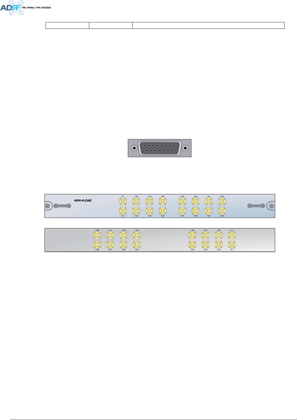
Advanced RF Technologies, Inc. 33
threshold level.
5 )3RUWV
'/,18/287'3;SRUWV
DL IN/UL OUT & DPX Ports (refer to Figure 3-7) are located at the back of RFU and can be
connected directly to the BDA or the BTS. A BCU can be used before inserting the signal into the RFU if
multiple multiple BDA or BTS sources exist. The RFU can support an incoming signal strength from 0 to
25 dBm.
'/2878/,1
DL OUT/UL IN Ports (refer to Figure 3-7) are located at the front of RFU and connect directly to the
HE Channel Combiner (ADX-H-CHC).
& RPPXQLFDWLRQ3RUW
ADX DAS-NMS monitors and controls a RFU via this port. DC Power is also provided to the RFU via
this port.
)LJXUH &RPPXQLFDWLRQ3RUW5)8
& KDQQHO&RPELQHU$';+&+&
)LJXUH$';+&+&)URQW5HDU9LHZ
x Functions & Features
- Combines DL signals received from each RFU and divides to all connected RUs
- Combines UL signals received from each RU and divides to all connected RFUs
- Supports up to 8 RFUs and (4) ADX-H-OPT
x Spec
- Size: 16.9 x 12.9 x 1.7 inches (430 x 327 x 44 mm)
- Weight: 11.0 lbs (5.0 kg)
5 )SRUWV
5)SRUWVDWWKHIURQWSDQHO'/WR'/8/WR8/
DL 1(to DL 8) & UL 1(to UL 8) RF ports are connected to DL OUT/UL IN Ports at the front panel of
RFU.
x Receive the downlink signal from each RFU
x Split the uplink signal received from OPT to each RFU
5)SRUWVDWWKHEDFNSDQHO'/WR'/8/WR8/
DL 1(to DL 8) & UL 1(to UL 8) RF ports are connected to DL IN/UL OUT Ports at the back panel of
OPT.
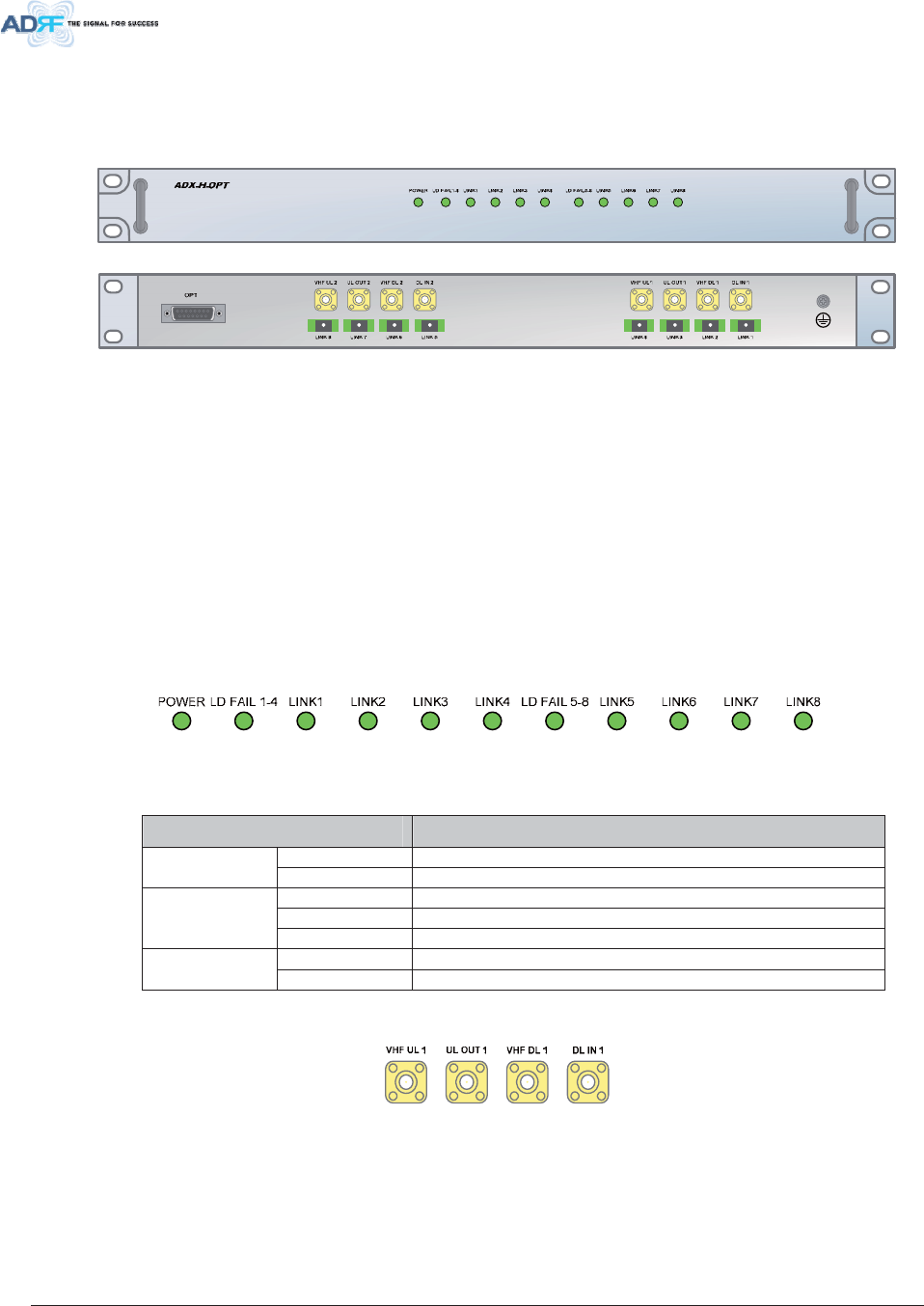
Advanced RF Technologies, Inc. 34
x Transfer the combined downlink signals to OPT
x Receive the uplink signal from OPT
2SW LF8QLW$';+237
)LJXUH$';+237)URQW5HDU9LHZ
x Functions & Features
- Converts RF to optic signal and transports signals up to a maximum of 10Km (optical 5dBo loss
including optical connection loss).
- Supports up to (8) Master RUs
- Minimizes the number of optic fiber cable neeed by transporting multi band signals over a single
strand of fiber using WDM technology.
x Spec
- Size: 19.0 x 12.9 x 1.7 inches (482 x 327 x 44 mm)
- Weight: 13.2 lbs (6.0 kg)
/ ('V
The ADX-H-OPT has the following LEDs on the front panel as shown in Figure 3-12.
)LJXUH237/('
7DEOH 237/('6SHFLILFDWLRQV
$';'$60RGXOH 6SHFLILFDWLRQV
Solid Green Module power is ON Power
OFF Module power is OFF
OFF ODU is not installed
Solid Yellow LD Fail alarm exists in the ODU
LD FAIL 1-4/
LD FAIL 5-8
Solid Green No LD Fail alarm is present in the ODU
Solid Yellow PD Fail alarm exists LINK1 to
LINK8 Solid Green No PD Fail alarm is present
5 )SRUWV
)LJXUH2375)3RUWV
'/,18/287
The combined downlink signal received from ADX-H-CHC is transferred to the DL IN 1(or 2) at the
back of OPT.
UL OUT is connected to one port among UL 1 to UL 8 ports at the back panel of ADX-H-CHC.
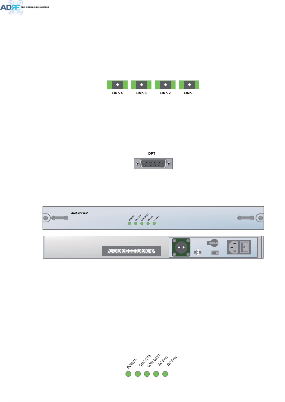
Advanced RF Technologies, Inc. 35
9+)'/9+)8/
VHF DL/UHF UL is used to support Public Safety in the VHF & UHF frequency band. VHF/UHF
signals for Public Safety are not combined by ADX-H-CHC but VHF/UHF signals received from RFU for
VHF/UHF are directly connected to the VHF DL/UHF UL port of OPT.
2SW LFSRUWV
)LJXUH2372SWLF3RUWV
One ADX-H-OPT has (8) optic ports and can support up to (8) Master RU’s.
& RPPXQLFDWLRQ3RUW
ADX-H-NMS monitors and controls a OPT via this port. DC Power is provided from the PSU to a OPT
via this port.
)LJXUH&RPPXQLFDWLRQ3RUW237
3RZHU6XSSO\8QLW$';+368
)LJXUH$';+368)URQW5HDU9LHZ
x Functions & Features
- Capable of supplying power to 8 RFUs, 4 BCUs, 4 OPTs and NMS
- Support Battery Backup via ADRF-BBU
x Spec
- Size: 16.9 x 13.1 x 1.7 inches (430 x 332.7x 44 mm)
- Weight: 7.7lbs (3.5 kg)
- Power Input: 110V or 220VAC, selectable by switch
/ ('V
ADX-H-PSU has the following LEDs on the front panel as shown in Figure 3-17.
)LJXUH+(368/('
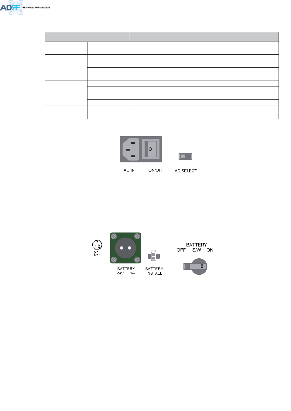
Advanced RF Technologies, Inc. 36
7DEOH +(368/('6SHFLILFDWLRQV
$';'$60RGXOH 6SHFLILFDWLRQV
Solid Green Module power is ON Power
OFF Module power is OFF
Solid Yellow No AC power is available and ADRF-BBU is being used
Blinking Green PSU is charging the ADRF-BBU
Solid Green ADRF-BBU is completely charged
CHG STS
OFF Battery is not connected
Solid Yellow Low Battery alarm exist in the PSU LOW BATT
Solid Green No Low Battery alarm is present in the PSU
Solid Yellow AC Fail alarm exists in the PSU AC FAIL
Solid Green No AC Fail alarm is present in the PSU
Solid Yellow DC Fail alarm exists in the RFU DC FAIL
Solid Green No DC Fail alarms is present in the PSU
$&,QSXW2Q2II6ZLWFK$&,QSXW3RUWDQG$&,QSXW6HOHFWLRQ6ZLWFK
)LJXUH+(368$&,QSXW2Q2II6ZLWFK$&,QSXW3RUWDQG$&,QSXW6HOHFWLRQ6ZLWFK
The AC Power on/off switch is located at the back panel of HE PSU. HE PSU can be operated at the
AC110V and AC220V input but AC Input Voltage should be selected properly through AC input voltage
selection switch by the user.
%DWWHU\%DFNXS3RUW%DWWHU\,QVWDOO3RUWDQG%DWWHU\%DFNXS6ZLWFK
)LJXUH%DWWHU\%DFNXS3RUW%DWWHU\,QVWDOO3RUWDQG%DWWHU\%DFNXS6ZLWFK
The Battery Switch can be used to provide power to the optional External Backup Battery (ADRF-
BBU) (Figure 3-19).
The HE PSU can be connected to an ADRF-BBU (ADRF Battery Backup Unit) to provide power
during a power failure. If an ADRF-BBU is utilized, connect the ADRF-BBU to the HE PSU via the
external battery backup port as shown in Figure 3-19.
(WARNING: The circuit switch on the ADRF-BBU must be set to OFF before connecting the ADRF-
BBU to the HE PSU to prevent damage to the HE PSU or the ADRF-BBU and personal injury.)
Note: Please contact ADRF Technical Support for assistance if you are unfamiliar with the installation
procedure of our battery box.
The Battery Install port is used to let NMS know if an ADRF-BBU is connected to the HE PSU or not.
If an ADRF-BBU is connected without the cable connection to Battery Install port, the ADX-H-NMS will not
detect the ADRF-BBU.
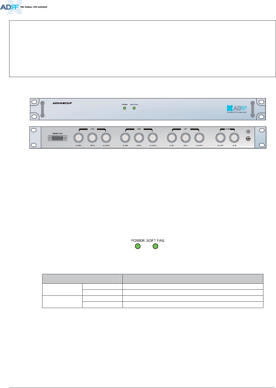
Advanced RF Technologies, Inc. 37
7KHSURFHGXUHIRUFRQQHFWLQJ+(368WR%%8
1. BATT S/W OFF
2. Connect ADRF-BBU to HE PSU Battery port and Battery Install port using HE battery
cable
3. BATT S/W ON
2SWLRQDO%DQG&RPELQHU8QLW$';+%&8[
)LJXUH$';+%&8)URQW5HDU9LHZ
x Functions & Features
- Combines and balances up to 3 carriers’ signals
- Easily adds multiple carriers’ signals without adding equipment
- Reduces complexity and expansion costs to support multiple carriers’ signals
x Spec
- Size: 19.0 x 12.9 x 1.7 inches (482 x 327 x 44 mm)
- Weight: 13.2 lbs (6.0 kg)
/ ('V
BCU has LEDs on the front panel as shown in Figure 3-21.
)LJXUH%&8/('
7DEOH %&8/('6SHFLILFDWLRQV
$';'$60RGXOH 6SHFLILFDWLRQV
Solid Green Module power is ON Power
OFF Module power is OFF
Solid Yellow Soft Fail alarm exist in the RFU Soft Fail
Solid Green No Soft Fail alarms are present in the RFU
5 )3RUWV
'/,18/287'3;SRUWV
DL IN/UL OUT & DPX Ports are located at the back of BCU and connect directly to the BDA or BTS.
'/2878/,1
DL OUT/UL IN Ports are located on the back of BCU and connect directly to the RFU.
& RPPXQLFDWLRQ3RUW
ADX-H-NMS monitors and controls a BCU via this port. DC Power is provided from PSU to a BCU via
this port.
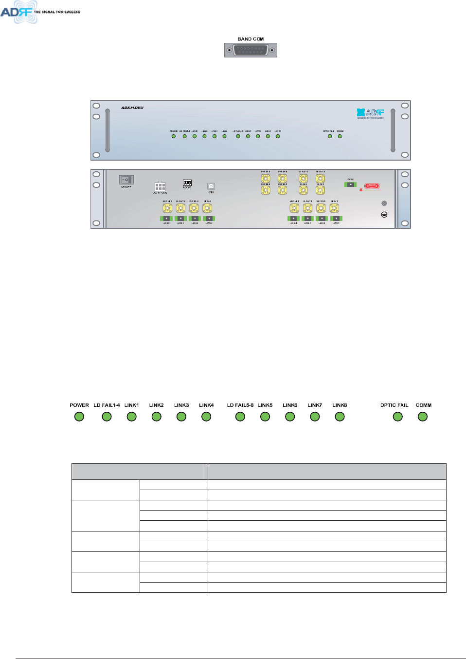
Advanced RF Technologies, Inc. 38
)LJXUH&RPPXQLFDWLRQ3RUW%&8
2SWLRQDO2SWLF([SDQVLRQ8QLW$';+2(8
)LJXUH$';+2(8)URQW5HDU9LHZ
x Functions & Features
- Used to extend DAS coverage to other buildings
- Drives up to (8) additional Master RUs
- Provides DAS coverage in remote building with minimized equipment and minimum optic line
x Spec
- Size: 19.0 x 12.8 x 3.5 inches (482 x 325 x 89 mm)
- Weight: TBD lbs (TBD kg)
- Power Input: 110VAC or -48VDC(optional)
/ ('V
OEU has the following LEDs on the front panel as shown in Figure 3-12.
)LJXUH237/('
7DEOH 237/('6SHFLILFDWLRQV
$';'$60RGXOH 6SHFLILFDWLRQV
Solid Green Module power is ON Power
OFF Module power is OFF
OFF ODU is not installed
Solid Yellow LD Fail alarm exist in the OEU
LD FAIL 1-4/
LD FAIL 5-8
Solid Green No LD Fail alarm is present in the OEU
Solid Yellow PD Fail alarm exist LINK1 to
LINK8 Solid Green No PD Fail alarm is present
Solid Yellow Optic Fail alarm exist in the OEU Optic Fail
Solid Green No Optic Fail alarm is present in the OEU
Solid Yellow COMM Fail alarm exist in the OEU COMM
Solid Green No COMM Fail alarm is present in the OEU
2SW LFSRUWV
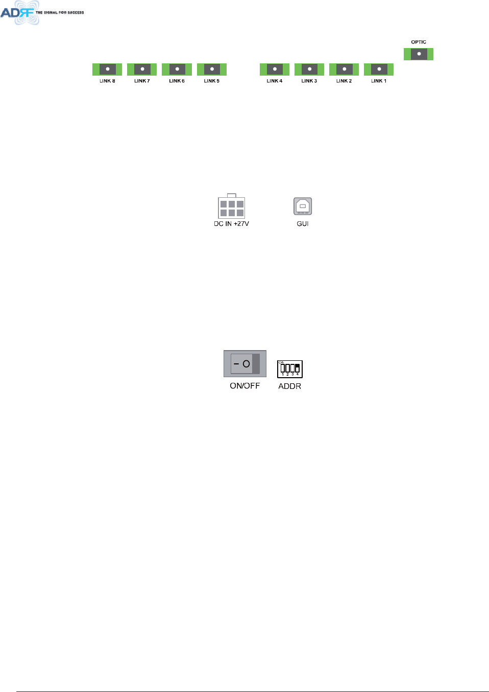
Advanced RF Technologies, Inc. 39
)LJXUH2(82SWLF3RUWV
x OPTIC port
- connected to OPT of HE
x LINK 1~8 ports
- connected to extended RUs
'&3RZHU,QSXWSRUW*8,3RUW
)LJXUH'&3RZHU,QSXW3RUW*8,3RUW
x DC IN Port
- Connect DC output of AC/DC adaptor to the OEU’s DC IN Port
x GUI Port
- Connects to laptop via USB cable (32-bit/64-bit Windows only supported)
- Used for interal purposes only
3RZHU2Q2II6ZLWFK$''5
)LJXUH3RZHU2Q2II6ZLWFK$''5
x ON/OFF switch
- OEU Power On/Off switch
x ADDR switch
- The ID of OEU can be set manually using ADDR switch in case the ID of OEU is not correctly
assigned automatically.
2 (8%ORFN'LDJUDP
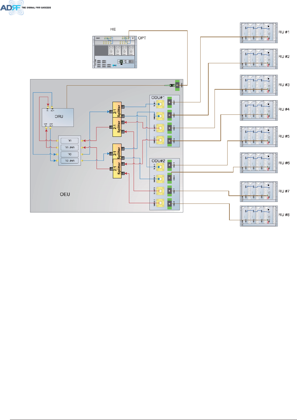
Advanced RF Technologies, Inc. 40
POW
ER
SOFTFAIL
H
AR
DFAIL
POWER
SOF
TFAIL
H
ARDF
AIL
P
OWER
SOF
TFAIL
H
ARDF
AIL
POWER
SOF
TFAIL
H
ARDF
AIL
COM
M
OP
TICF
AIL
POW
ER
SOFTFAIL
HAR
DFAIL
POW
ER
SOF
TF
AIL
HARDF
AIL
POW
ER
SOF
TF
AIL
H
ARDF
AIL
POW
ER
SOF
TFAIL
HARDF
AIL
COM
M
OPTICFAIL
POW
ER
SOFTFAIL
HAR
DFAIL
POW
ER
SOF
TF
AIL
HARDF
AIL
P
OW
ER
SOF
TF
AIL
H
ARDF
AIL
POW
ER
SOF
TFAIL
HARDF
AIL
COM
M
OPTICF
AIL
POW
ER
S
OFTFAIL
HAR
DFA
IL
POWE
R
SOFTF
AIL
HAR
DFAIL
POWER
SOFTFAIL
H
AR
DFAIL
POWE
R
SOFTFAIL
HAR
DFAIL
C
OMM
OPTICFAIL
POW
ER
SOFTFA
IL
H
AR
DFAIL
POWER
SOF
TFAIL
H
ARDF
AIL
P
OWER
SOF
TFAIL
HARDF
AIL
POWER
SOF
TFAIL
H
ARDF
AIL
COM
M
OP
TICF
AIL
POW
ER
S
OFTFAIL
HAR
DFA
IL
POWE
R
SOFTF
AIL
HAR
DFAIL
POWER
SOFTF
AIL
H
AR
DFAIL
POWE
R
SOFTFAIL
HAR
DFAIL
C
OMM
OPTICFAIL
POW
ER
SOFTFAIL
HAR
DFAIL
POW
ER
SOF
TF
AIL
HARDF
AIL
POW
ER
SOF
TF
AIL
H
ARDF
AIL
POW
ER
SOF
TFAIL
HARDF
AIL
COM
M
OPTICF
AIL
POW
ER
S
OFTFAIL
HAR
DFA
IL
POWE
R
SOFTF
AIL
HAR
DFAIL
POWER
SOFTF
AIL
H
AR
DFAIL
POWE
R
SOFTFAIL
HAR
DFAIL
C
OMM
OPTICFAIL
)LJXUH2(8%ORFN'LDJUDP
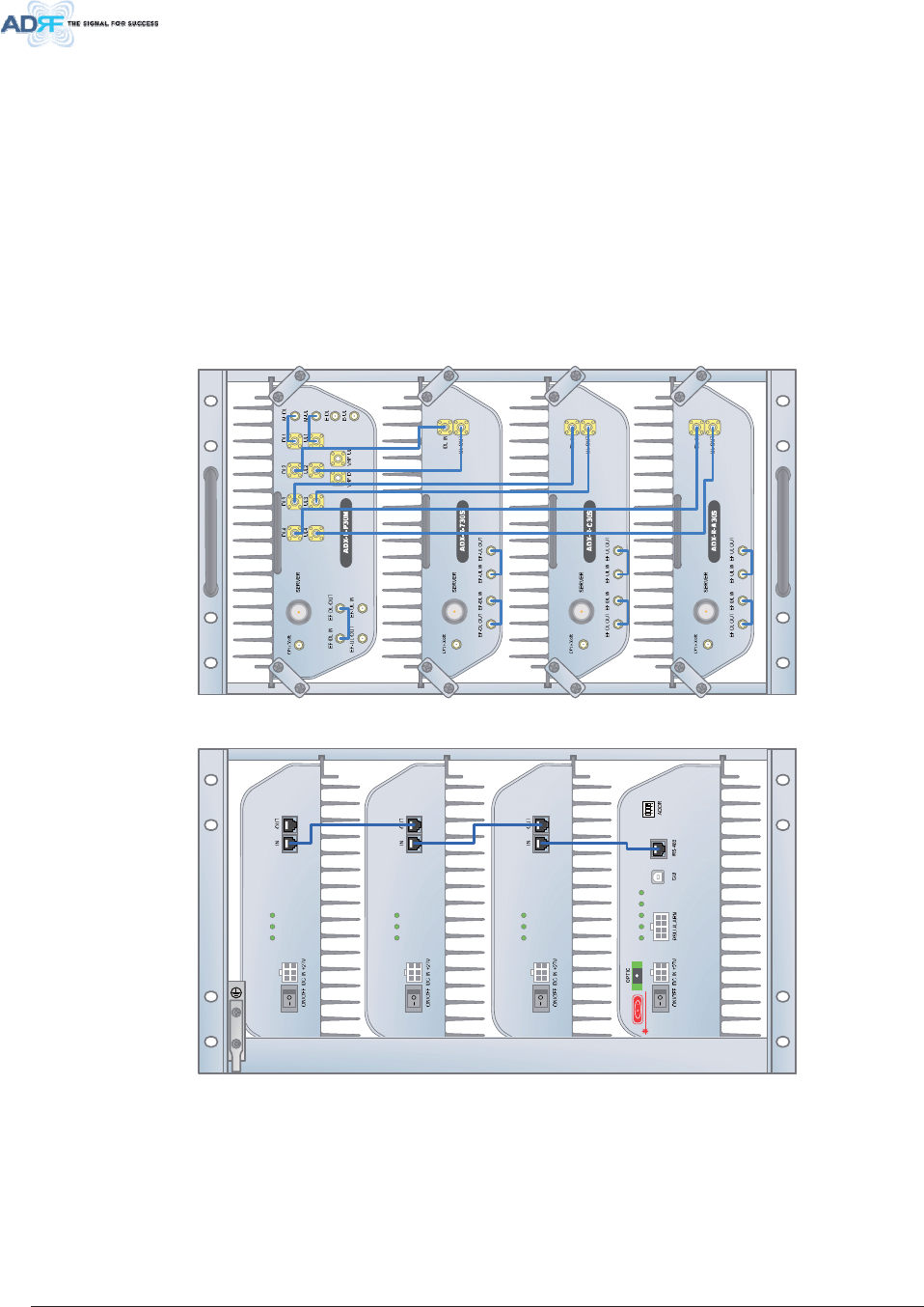
Advanced RF Technologies, Inc. 41
5 8$';5[06
RU is composed of a (1) Master RU and up to (7) Slave RU’s (use the use of ADX-R-4WS). A power
supply, either the ADX-R-ADP (supports [1] Master/Slave RU) or ADX-R-PSU-30 (supports up to [8]
Master/Slave RU) is required.
x Spec
- Size: 19.0 x 12.9 x 10.5 inches (482 x 328.2 x 266.5 mm)
- Weight: 61.0 lbs (27.7 kg)
- Power Input: 110VAC or -48VDC(optional)
- Battery Backup supported
)LJXUH58)URQW9LHZ
POWER
SOFTFAIL
HARDFAIL
POWER
SOFTFAIL
HARDFAIL
POWER
SOFTFAIL
HARDFAIL
POWER
SOFTFAIL
HARDFAIL
COMM
OPTICFAIL
)LJXUH585HDU9LHZ
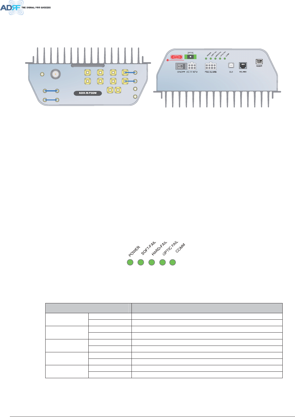
Advanced RF Technologies, Inc. 42
0 DVWHU58$';5[0
SERVER
UL4UL3UL2UL1
DL4DL3DL2DL1
M-DL
M-UL
CPL(-30dB)
E-DL
E-UL
VHF DL VHF UL
EF-DL IN EF-DL OUT
EF-UL INEF-UL OUT
)LJXUH0DVWHU58)URQW5HDU9LHZ
x Functions & Features
- Converts optic signal into RF signal
- Divides and provides RF signals to Slave RU
- Transmits DL signal and receives UL signal through server antenna
- Drive up to 7 slave RUs
- Eliminate the need of fans by applying convection cooling structure for wall mount application
- Efficiently solves out of band interference problems by supporting external filters
- Easy to install and add RUs since each RU is independent and modular
x Spec
- Size: 11.8 x 9.8 x 4.5 inches (300 x 249.6 x 114.5 mm)
- Weight: 13.2 lbs (6.0 kg)
/ ('V
Master RU’s have the following LEDs on the front panel as shown in Figure 3-32.
)LJXUH0DVWHU58/('
7DEOH 0DVWHU58/('6SHFLILFDWLRQV
$';'$60RGXOH 6SHFLILFDWLRQV
Solid Green Module power is ON Power
OFF Module power is OFF
Solid Yellow Soft Fail alarm exists in the Master RU Soft Fail
Solid Green No Soft Fail alarms are present in the Master RU
Solid Red Hard Fail alarm exists in the Master RU Hard Fail
Solid Green No Hard Fail alarms are present in the Master RU
Solid Yellow Optic Fail alarm exists in the Master RU Optic Fail
Solid Green No Optic Fail alarm is present in the Master RU
Solid Yellow COMM Fail alarm exists in the Master RU COMM
Solid Green No COMM Fail alarm is present in the Master RU
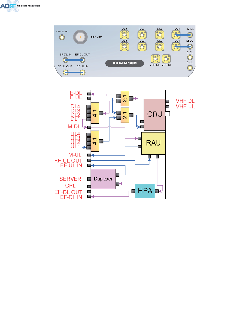
Advanced RF Technologies, Inc. 43
5 )3RUWV
)LJXUH5)3RUWV0DVWHU58
)LJXUH0DVWHU58EORFN'LDJUDPDQG5)3RUW1DPH
0'/08/'/WR'/8/WR8/
x M-DL/M-UL ports
- Master RU units will come with the M-DL and M-UL ports pre-connectedt to the DL1 and UL1
ports.
x DL2 to DL4 & UL2 to UL4 ports
- DL2 through DL4 and UL2 through UL4 ports are used to connect additional Slave RU units.
( '/(8/
x Used to support additional (4) Slave RU units in addition to the (1) Master RU unit and (3) Slave
RU units already being utlized
x An ADX-R-4WS is required if utilizing the E-DL/E-UL ports
x ADX-R-4WS divides the output of E-DL port to extended slave RUs and combines/transfers UL
signal received from extended slave RUs to E-UL port. (refer to section 3.2.4, Figure 4-4)
9+)'/9+)8/
x Used to support Slave RU for public safety service of VHF/UHF band (ADX-R-V30S)
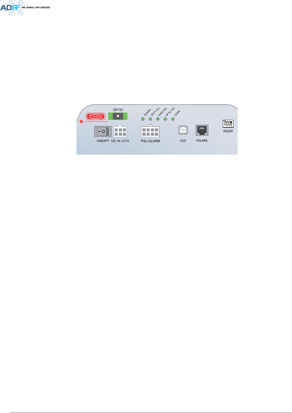
Advanced RF Technologies, Inc. 44
6(59(5 &3/
x Server Port
- Connected to Server Antenna or RU channel combiner (ADX-R-CHC).
x CPL Port
- 30dB coupling port of Server port.
()'/,1()'/287()8/,1()8/287
x Can be connected to the DL/UL external filter
x DL external filter can be used to reduce DL out-band emissions
x UL external filter can be used to reduce out-band frequenies
)LJXUH3RUWVDWWKHEDFNSDQHO0DVWHU58
2 SWLF3RUW
x Connets to ADX-H-OPT via optic line
3RZHU2Q2II6ZLWFK'&,13RUW
x Power On/Off switch
- Master RU Power On/Off switch
x DC IN Port
- Connected to DC output port of AC/DC adaptor (ADX-R-ADP-30) or RU PSU (ADX-R-PSU-30)
3 68$ODUP3RUW
x Connected to the ADX-R-PSU-30
x NMS & master RU can monitor the status of RU PSU via this port
* 8,3RUW
x Connects to a laptop via USB cable
x Monitor/control the RU and the HE connected to the RU using User GUI, which is a Windows
based program. ADRF 32-bit or 64-bit drivers will also be required to access the RU using the User
GUI.
5 63RUW
x Slave RU should be connected to master RU in a diasy chain structure using RS-485 line to
monitor and control slave RUs.
x The RS-485 cable connected to master RU should be connected to RS-485 IN port of slave RU.
When a slave RU is connected to another slave RU, then the RS-485 cable should be connected
from the RS-485 OUT port to the RS-485 IN of the 2nd Slave RU. (Figure 3-36)
x If RS-485 port connections between sub RUs are not correct, master RU will not be able to
recognize all subordinate slave RUs. (Figure 3-37)
xWARNING! The RS-485 ports should NEVER be connected to the Enthernet port of laptop
or Ethernet Network Equipment. Doing so may cause serious damage to the sub RUs or
network equipments. (Figure 3-38)
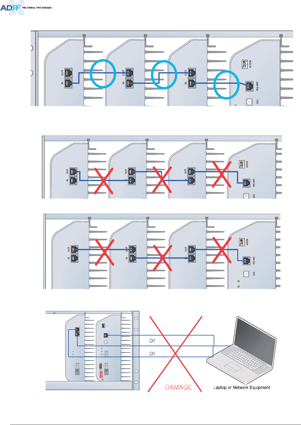
Advanced RF Technologies, Inc. 45
)LJXUH&RUUHFW56FRQQHFWLRQEHWZHHQ0DVWHU58DQG6ODYH58RUEHWZHHQ6ODYH
58V
R
D
FAIL
R
D
FAIL
R
D
FAIL
R
D
FAIL
COMM
OPTICFAIL
)LJXUH:URQJ56FRQQHFWLRQEHWZHHQ0DVWHU58DQG6ODYH58RUEHWZHHQ6ODYH58V
DC IN +27VON/OFF
OUT
POWER
SOFT FAIL
HARD FAIL
IN
POWER
SOFT FAIL
HARD FAIL
COMM
OPTIC FAIL
DC IN +27V PSU ALARM RS-485GUI
OPTIC
ON/OFF
ON
ADDR
)LJXUH'R127FRQQHFW56SRUWVRI6XE58WRQHWZRUNHTXLSPHQWSRUW
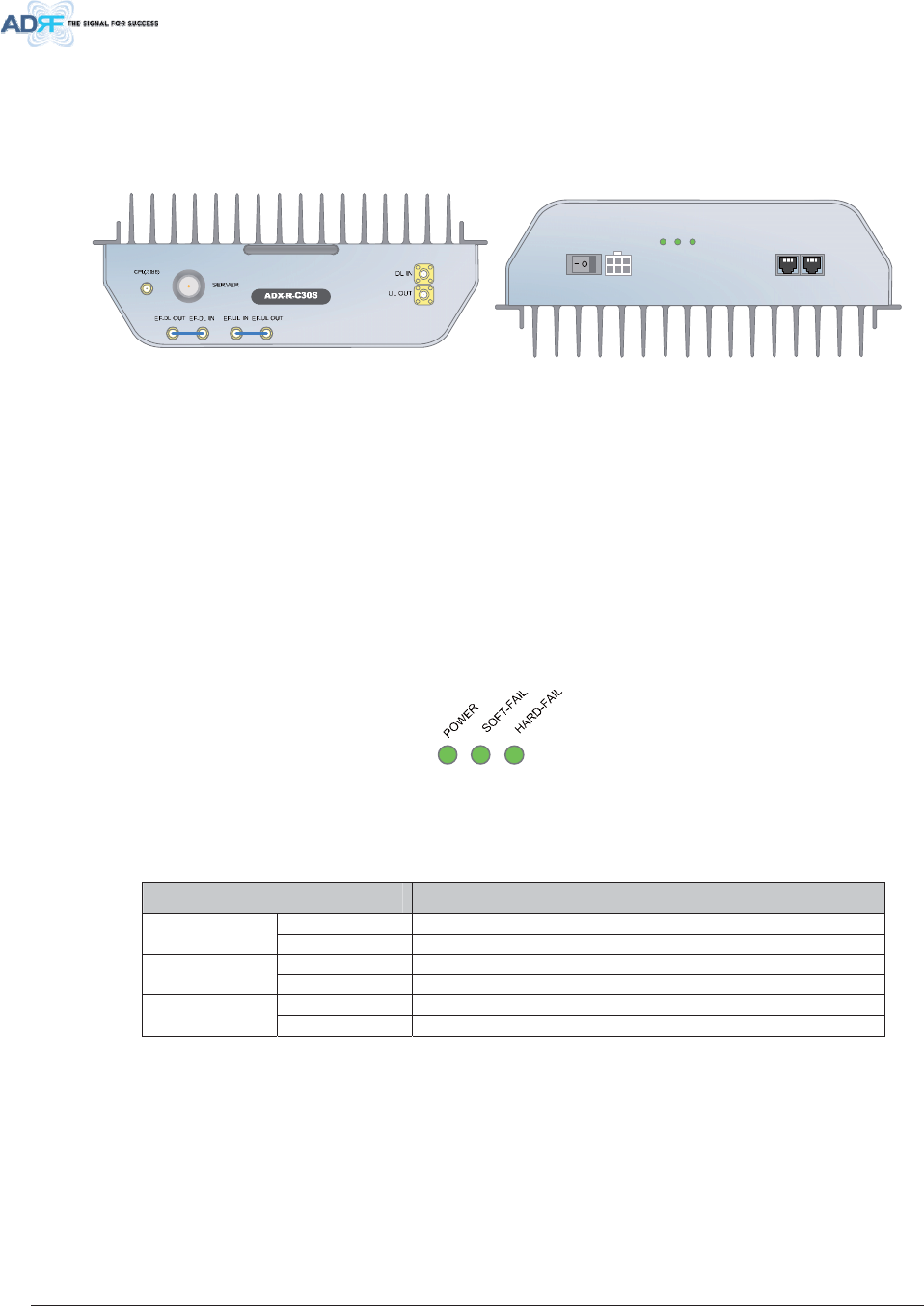
Advanced RF Technologies, Inc. 46
$ ''5
x The ID of master RU can be set manually using ADDR switch. This switch should only be use if
instructed by ADRF Technical Support.
6ODYH58$';5[6
DC IN +27VON/OFF
OUT
POWER
SOFT FAIL
HARD FAIL
IN
)LJXUH6ODYH58)URQW5HDU9LHZ
x Functions & Features
- Transmits DL signal and receives UL signal through server antenna port
- Eliminate the need for fans by applying convection cooling structure for wall mount application
- Efficiently solves out of band interference problems by supporting external filter
- Easy to install and add RUs since each RU is independent and modular
x Spec
- Size: 11.8 x 9.8 x 3.7 inches (300 x 249.6 x 94.5 mm)
- Weight: 11.7 lbs (5.3 kg)
/ ('V
ADX DAS has the following LEDs on the front of the Slave RU as shown below in Figure 3-32.
)LJXUH6ODYH58/('
7DEOH 6ODYH58/('6SHFLILFDWLRQV
$';'$60RGXOH 6SHFLILFDWLRQV
Solid Green Module power is ON Power
OFF Module power is OFF
Solid Yellow Soft Fail alarm exists in the Slave RU Soft Fail
Solid Green No Soft Fail alarms are present in the Slave RU
Solid Red Hard Fail alarm exists in the Slave RU Hard Fail
Solid Green No Hard Fail alarms are present in the Slave RU
5 )3RUWV
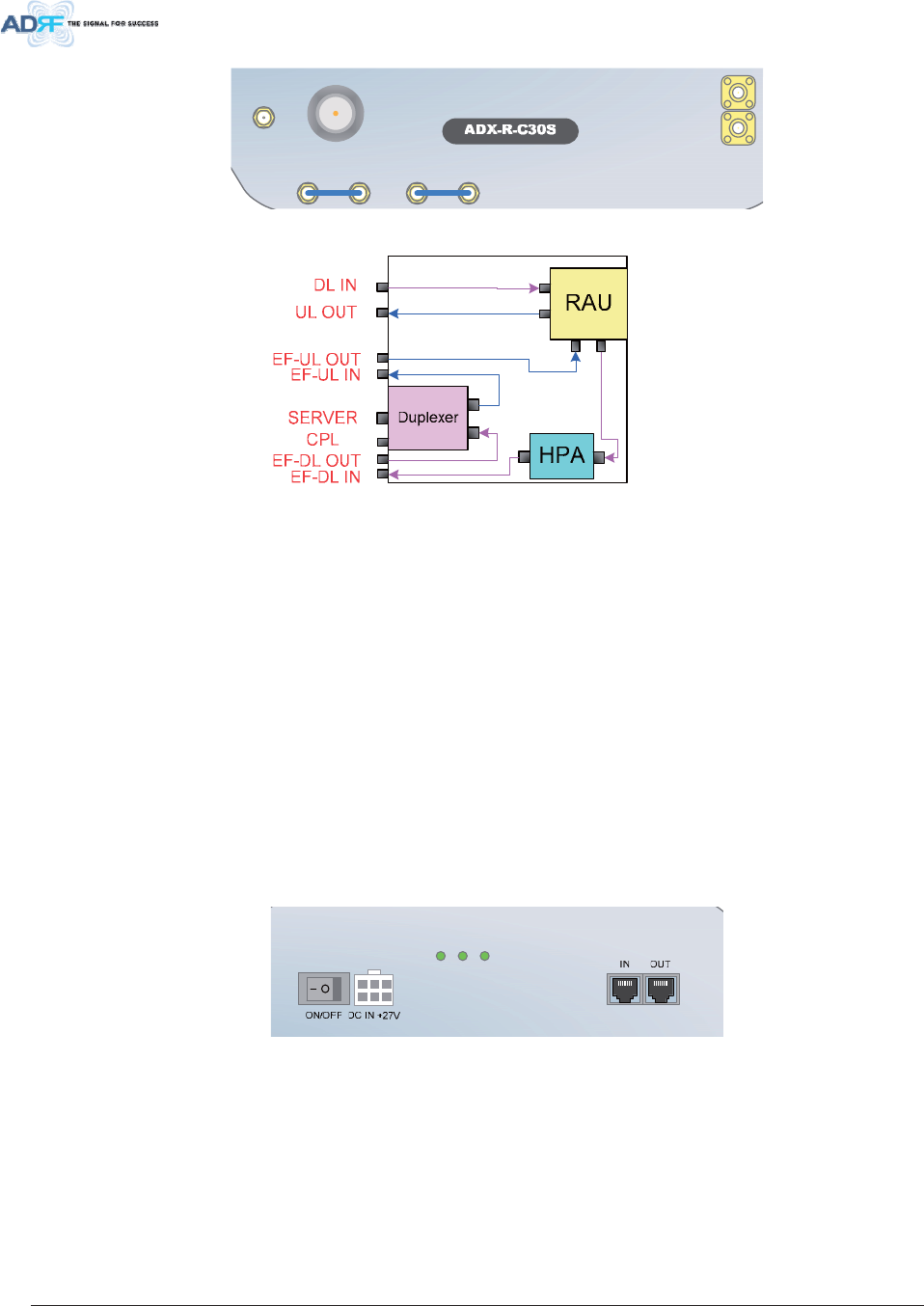
Advanced RF Technologies, Inc. 47
DL IN
SERVER
CPL(-30dB)
UL OUT
EF-DL OUT EF-DL IN EF-UL IN EF-UL OUT
)LJXUH5)3RUWV6ODYH58
)LJXUH6ODYH58EORFN'LDJUDPDQG5)3RUW1DPH
'/,18/287
x Connects to one of the avaialble DL 2 to 4/UL 2 to 4 ports of master RU
x DL IN port receives the divided DL output of master RU
x UL OUT port transfers the UL output of slave RU to master RU
6(59(5 &3/
x Server Port
- Connects to a Server Antenna or RU channel combiner (ADX-R-CHC)
x CPL Port
- 30dB coupling port from the Server port
()'/,1()'/287()8/,1()8/287
x Can be connected to the DL/UL external filter
x DL external filter can be used to reduce out-band emissions
x UL external filter can be used to reduce uplink out-band signals
POWER
SOFT FAIL
HARD FAIL
)LJXUH3RUWVDWWKHUHDUSDQHO6ODYH58
3RZHU2Q2II6ZLWFK'&,13RUW
x Power On/Off switch
- Slave RU Power On/Off switch
x DC IN Port
- Connected to DC output port of AC/DC adaptor (ADX-R-ADP-30) or RU PSU (ADX-R-PSU-30)
5 63RUW
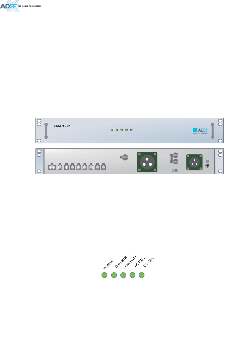
Advanced RF Technologies, Inc. 48
x Slave RU is connected to master RU or other slave RU in a diasy chain structure using RS-485
line to monitor and control slave RUs.
x The RS-485 cable connected to master RU should be connected to RS-485 IN port of slave RU.
When a slave RU is connected to another slave RU, then the RS-485 cable should be connected
from the RS-485 OUT port to the RS-485 IN of the 2nd Slave RU. (Figure 3-36)
x If RS-485 port connections between sub RUs are not correct, master RU will not be able to
recognize all subordinate slave RUs. (Figure 3-37)
xWARNING! The RS-485 ports should NEVER be connected to the Enthernet port of laptop
or Ethernet Network Equipment. Doing so may cause serious damage to the sub RUs or
network equipments. (Figure 3-38)
583RZHU6XSSO\2SWLRQV
583RZHU$GDSWHU$';5$'3
One power adapter can support up to (1) sub-RU.
58368$';5368
32:(5
&+*676
/2:%$77
$&)$,/
'&)$,/
$&,1
$ $&B/% $&B1& )*
$&6(/(&7
%$77(5<6:
%$77(5<9
368$/$50 '&287
9
'&287
9
'&287
9
'&287
9
'&287
9
'&287
9
'&287
9
'&287
9
32:(56:
2))21
)LJXUH58368)URQW5HDU9LHZ
x Functions & Features
- Capable of supplying power to 8 Sub Rus (Master/Slave RU)
- Support Battery Backup (24V DC output)
x Spec
- Size: 19.0 x 12.0 x 2.6 inches (482 x 304x 66 mm)
- Weight: 9.9lbs (4.5 kg)
- Power Input: 110V or 220VAC, selectable by switch
/ ('V
ADX DAS has the following LEDs on the front of the RU PSU as shown below in Figure 3-45.
)LJXUH58368/('
7DEOH 58368/('6SHFLILFDWLRQV
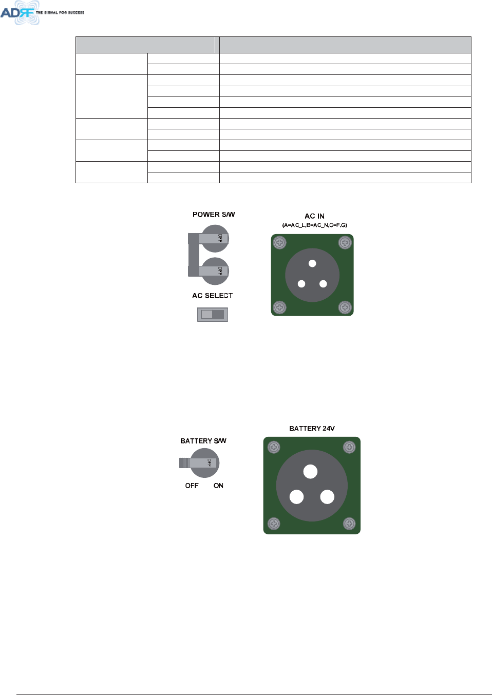
Advanced RF Technologies, Inc. 49
$';'$60RGXOH 6SHFLILFDWLRQV
Solid Green Module power is ON Power
OFF Module power is OFF
Solid Yellow No AC power detected and ADRF-BBU is being used
Blinking Green ADRF-BBU is being charged
Solid Green Completely Charged
CHG STS
OFF Battery is not connected
Solid Yellow Low Battery alarm exist in the PSU LOW BATT
Solid Green No Low Battery alarm is present in the PSU
Solid Yellow AC Fail alarm exist in the PSU AC FAIL
Solid Green No AC Fail alarm is present in the PSU
Solid Yellow DC Fail alarm exist in the RFU DC FAIL
Solid Green No DC Fail alarms is present in the PSU
$&,QSXW2Q2II6ZLWFK$&,QSXW3RUWDQG$&,QSXW6HOHFWLRQ6ZLWFK
)LJXUH583683RZHU6ZLWFK9LHZ
The AC Power on/off switch is located at the back panel of ADX-R-PSU-30. The ADX-R-PSU-30 can
be operated at the AC110V and AC220V input but AC Input Voltage should be selected properly through
AC input voltage selection switch by the user.
%DWWHU\%DFNXS3RUWDQG%DWWHU\%DFNXS6ZLWFK
)LJXUH%DWWHU\%DFNXS3RUW%DWWHU\%DFNXS6ZLWFK
The Battery Switch can be used to provide power to the optional ADRF-BBU (External Backup
Battery) (Figure 3-47).
The RU PSU can be connected to an ADRF-BBU (ADRF Battery Backup Unit) to provide power
during a power failure. If an ADRF-BBU is utilized, connect the ADRF-BBU to the RU PSU via the
external battery backup port as shown in Figure 3-47.
(WARNING: The circuit switch on the ADRF-BBU must be set to OFF before connecting the
ADRF-BBU to the HE PSU to prevent damage to the HE PSU or the ADRF-BBU and personal
injury.)
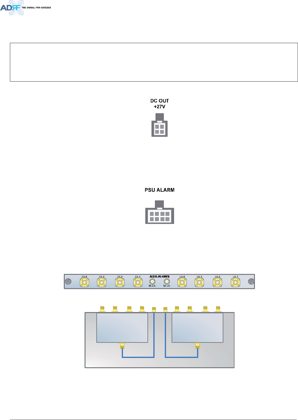
Advanced RF Technologies, Inc. 50
Note: Please contact ADRF Technical Support for assistance if you are unfamiliar with the installation
procedure of our battery box.
7KHSURFHGXUHIRUFRQQHFWLQJ58368WR%%8
1. BATT S/W OFF
2. Connect BBU to RU PSU Battery port using RU battery cable
3. BATT S/W ON
'&2XWSXW3RUW
)LJXUH'&2XWSXW3RUW58368
x The number of DC output port: 8
x DC Output Ports provide DC Power up to 8 Sub RUs.
3 68$ODUP3RUW
)LJXUH368$ODUP3RUW58368
x Connects to master RU
x NMS & master RU can monitor the status of the ADX-R-PSU-30 via this port.
2SWLRQDO:D\&RPELQHU$';5:6
)LJXUH$';5:6)URQW9LHZ
)LJXUH$';5:6,QQHU9LHZ
x ADX-R-4WS is required to when more than 4 sub-RU’s are being used
x ADX-R-4WS connects to E-DL/E-UL port of master RU
x ADX-R-4WS divides the output of E-DL port into extended slave RUs
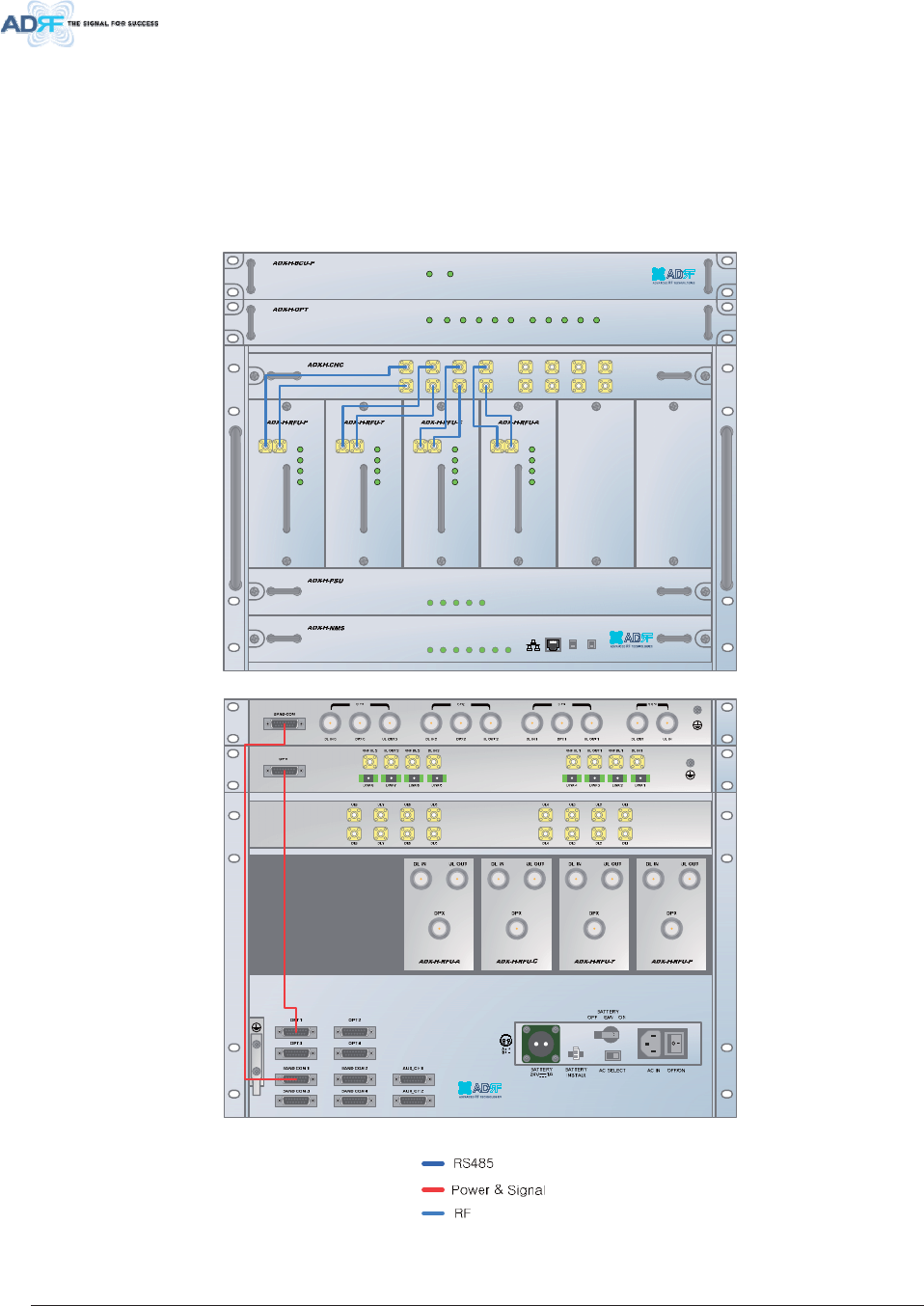
Advanced RF Technologies, Inc. 51
x ADX-R-4WS combines/transfers UL signal received from extended slave RUs to E-UL port (refer
to Figure 4-4)
& $%/(&211(&7,21
+HDG(QG&RQQHFWLRQ'LDJUDPV
)URQW5HDU+HDG(QG&RQQHFWLRQ9LHZZLWK2SWLRQDO%&8XQLW
32:(5
62)7)$,/+
62)7)$,/5
+$5')$,/+
+$5')$,/5
/,1.)$,/+
/,1.)$,/ 5
+267 +(9,(:
5(027( 589,(:
32:(5
&+*676
/2:%$77
$&)$,/
'&)$,/
'/2878/,1
+$5')$,/
'/6,*/2:
62)7)$,/
32:(5
'/2878/,1
+$5')$,/
'/6,*/2:
62)7)$,/
32:(5
'/2878/,1
+$5')$,/
'/6,*/2:
62)7)$,/
32:(5
'/2878/,1
+$5')$,/
'/6,*/2:
62)7)$,/
32:(5
8/ 8/ 8/ 8/
'/ '/ '/ '/
8/ 8/ 8/ 8/
'/ '/ '/ '/
/')$,/ /,1. /,1. /,1. /,1./')$,/ /,1. /,1. /,1. /,1.32:(5
62)7)$,/32:(5
)LJXUH +(&DEOHFRQQHFWLRQ237%&8
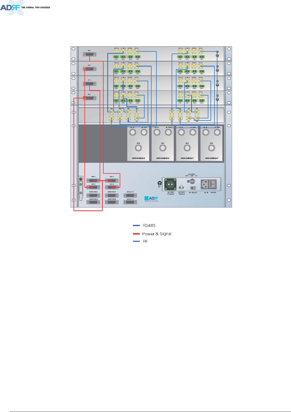
Advanced RF Technologies, Inc. 52
5HDU+HDG(QG&RQQHFWLRQ9LHZZLWK237XQLWV
)LJXUH +(&DEOHFRQQHFWLRQ237V
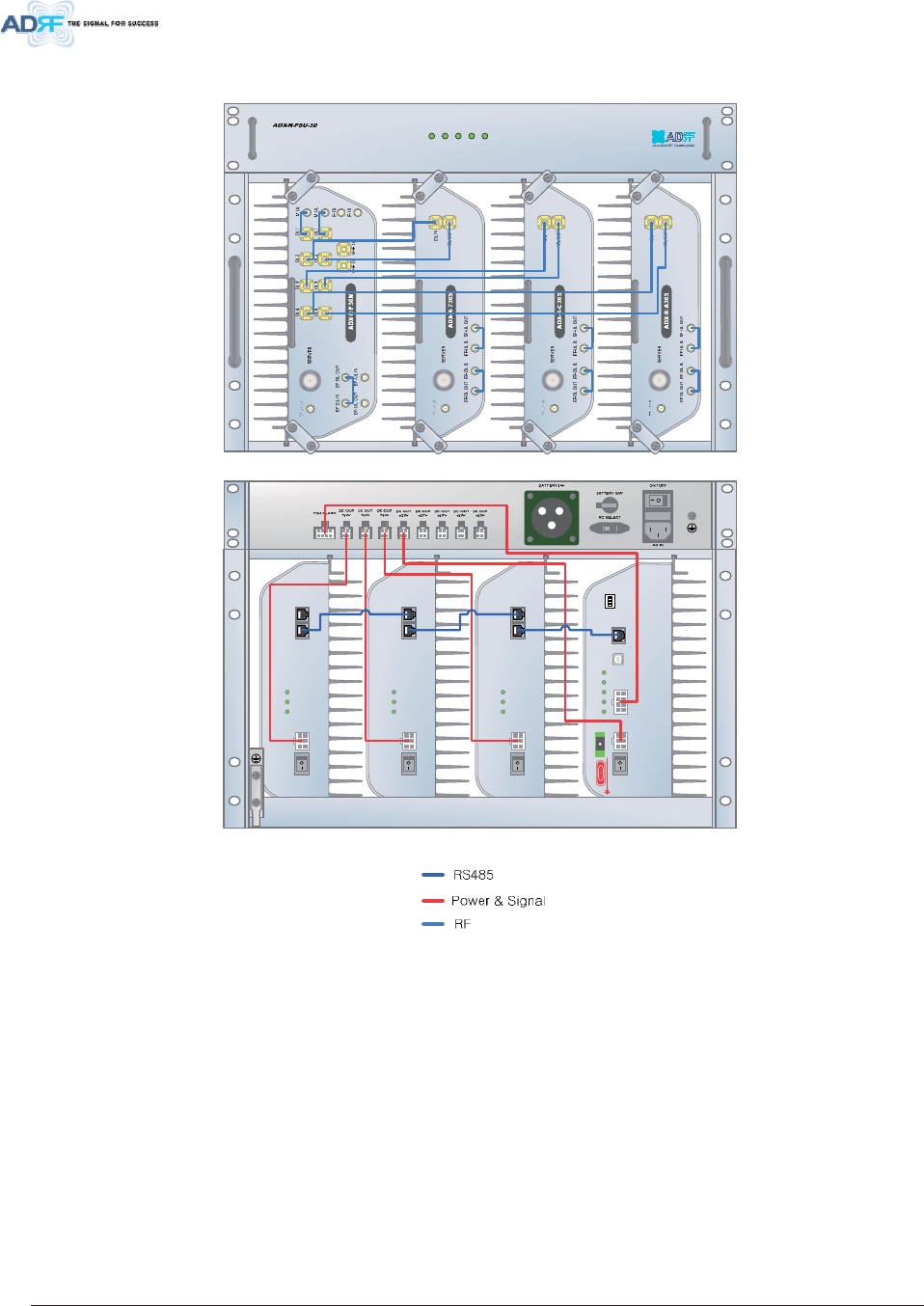
Advanced RF Technologies, Inc. 53
5HPRWH8QLW&RQQHFWLRQ'LDJUDPV
32:(5
&+*676
/2:%$77
$&)$,/
'&)$,/
OFF
DC IN +27VON/OFF
OUT
POWER
SOFT FAIL
HARD FAIL
IN
DC IN +27VON/OFF
OUT
POWER
SOFTFAIL
HARD FAIL
IN
DC IN +27VON/OFF
OUT
POWER
SOFT FAIL
HARD FAIL
IN
POWER
SOFT FAIL
HARD FAIL
COMM
OPTIC FAIL
DC IN +27V P SU ALARM RS-485GUI
OPTIC
ON/OFF
ON
ADDR
)LJXUH 58&DEOHFRQQHFWLRQ6XE5858368
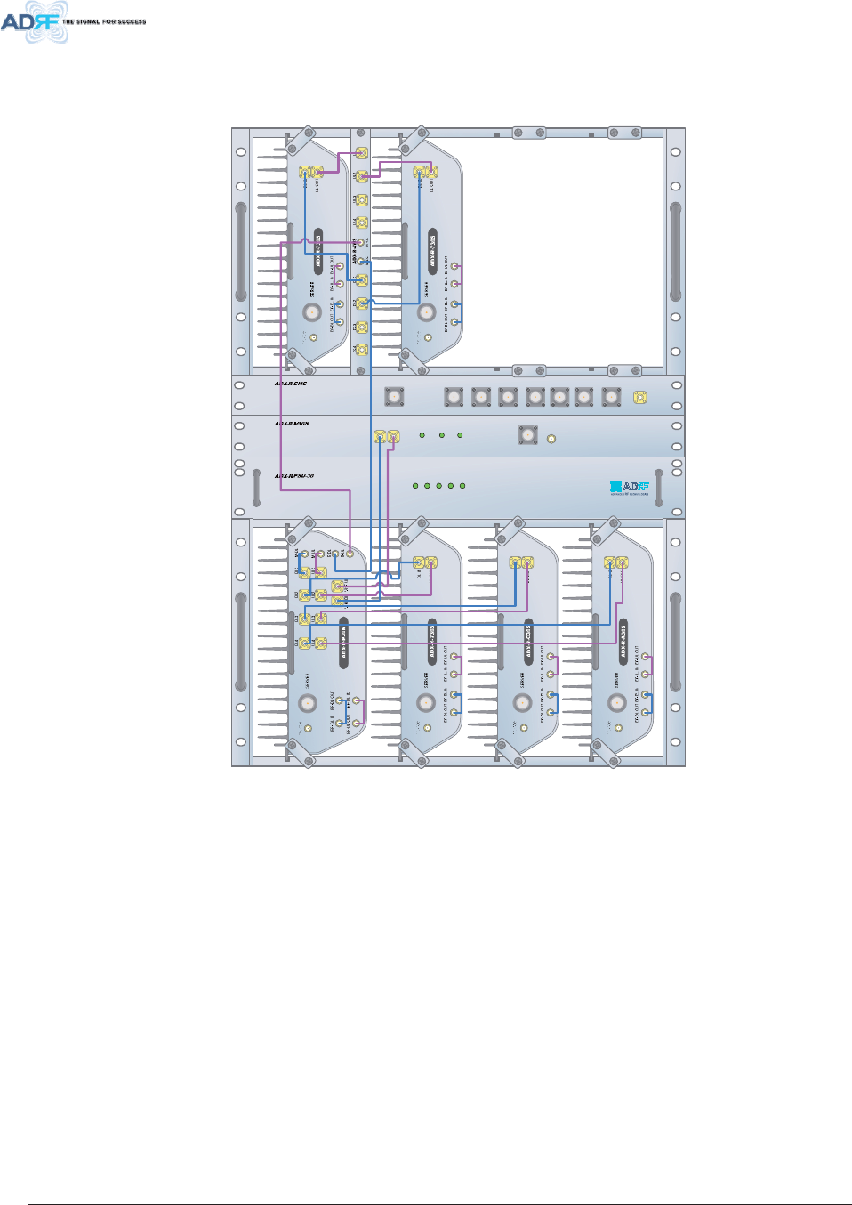
Advanced RF Technologies, Inc. 54
5HPRWH8QLWZ:D\&RPELQHU$';5:6
32:(5
&+*676
/2:%$77
$&)$,/
'&)$,/
~thjzty_WWh~z^WWtwjz
jvt WIFI
zty`WW
wv~ly zvm{Gmhps ohykGmhps
DL-IN UL-OUT MO N
SERVER
)LJXUH 6ODYH58([SDQVLRQXVLQJ$';5:6
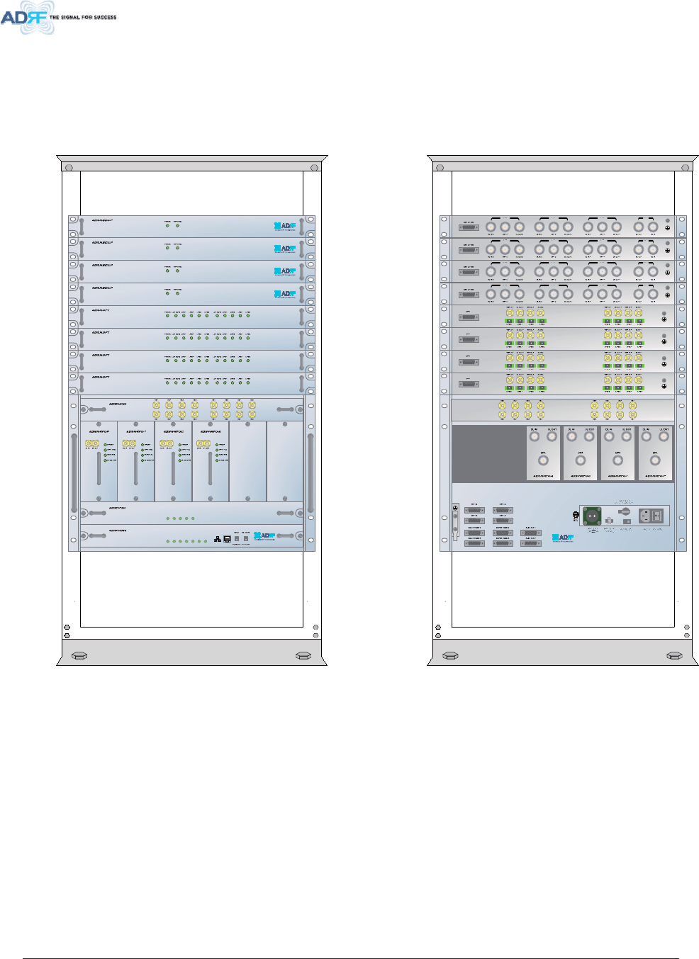
Advanced RF Technologies, Inc. 55
02817,1 *0(7+2'
+ HDG(QG
5 DFN0RXQW
32:(5
62)7)$,/+
62)7)$,/5
+$5')$,/+
+$5')$,/5
/,1.)$,/+
/,1.)$,/5
32:(5
&+*676
/2:%$77
$&)$,/
'&)$,/
)LJXUH +(5DFN0RXQW)URQW5HDUYLHZ
x Expandable up to 4 OPTs, 4 BCUs and 2 AUX CHs
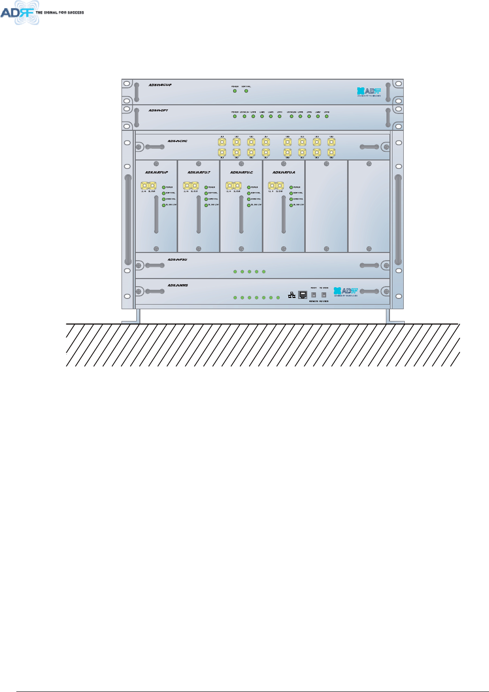
Advanced RF Technologies, Inc. 56
: DOO0RXQW
32:(5
62)7)$,/+
62)7)$,/5
+$5')$,/+
+$5')$,/5
/,1.)$,/+
/,1.)$,/5
32:(5
&+*676
/2:%$77
$&)$,/
'&)$,/
)LJXUH +(:DOO0RXQW7RS9LHZ
x Expandable up to 3 units (OPT, BCU) or max 3U (132mm)
- OPT or BCU will be stacked up above basic 19” HE chassis which includes NMS, RFU, PSU and
CHC
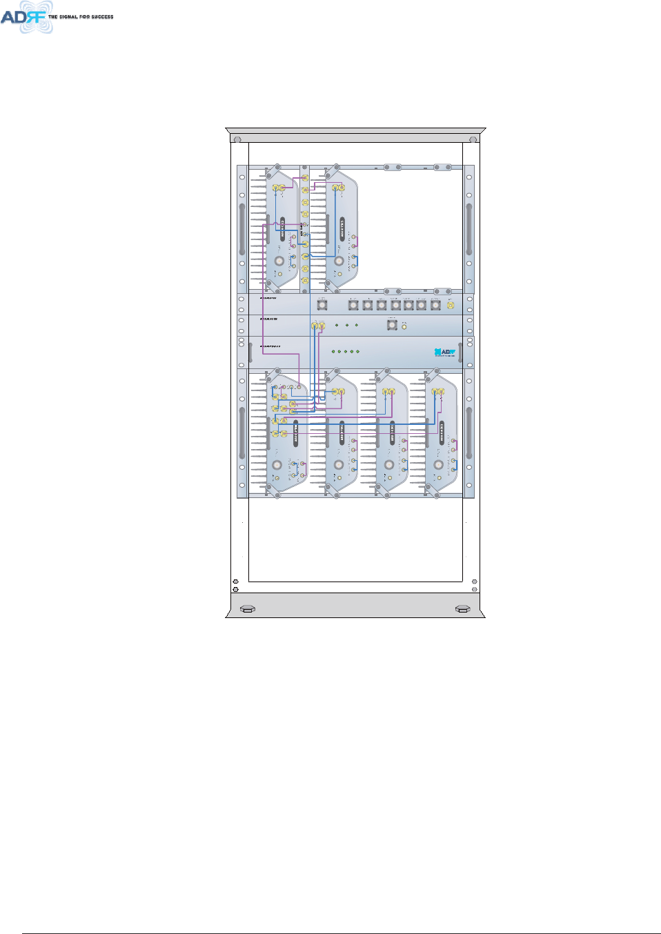
Advanced RF Technologies, Inc. 57
5H PRWH8QLW
5 DFN0RXQW
32:(5
&+*67 6
/2:%$77
$&)$,/
'&)$,/
)LJXUH 585DFN0RXQW)URQWYLHZ
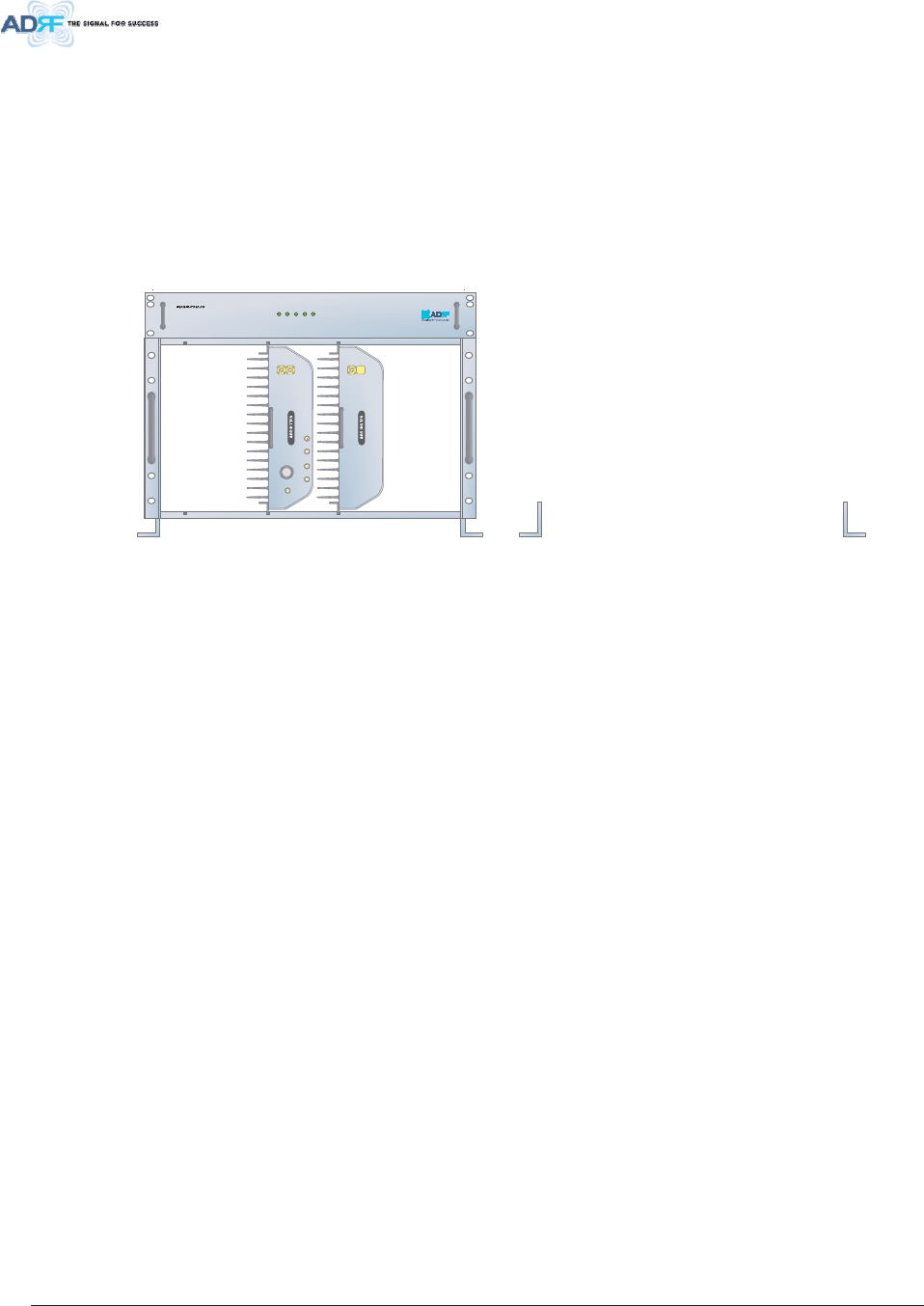
Advanced RF Technologies, Inc. 58
: DOO0RXQW
5HPRWH8QLWXVLQJ58&KDVVLV$';5&+$
Wall mount brackets attached to the individual Sub-RU’s must be removed before installing Sub-RU’s
to the RU Chassis.
32:(5
&+*676
/2:%$77
$&)$,/
'&)$,/
DL IN
SERVER
CPL(-30dB)
UL OUT
EF-DL OUT EF-DL IN EF-UL IN EF-UL OUT
DL IN
SERVER
CPL(-30dB)
.
,&:DUQLQJ
7KLVGHYLFHFRPSOLHVZLWK,QGXVWU\&DQDGDOLFHQFHH[HPSW566VWDQGDUGV
2SHUDWLRQLVVXEMHFWWRWKHIROORZLQJWZRFRQGLWLRQVWKLVGHYLFHPD\QRWFDXVHLQWHUIHUHQFHDQG
WKLVGHYLFHPXVWDFFHSWDQ\LQWHUIHUHQFHLQFOXGLQJLQWHUIHUHQFHWKDWPD\FDXVHXQGHVLUHGRSHUDWLRQRIWKHGHYLFH
/HSUpVHQWDSSDUHLOHVWFRQIRUPHDX[&15G,QGXVWULH&DQDGDDSSOLFDEOHVDX[DSSDUHLOVUDGLRH[HPSWVGHOLFHQFH
/H[SORLWDWLRQHVWDXWRULVpHDX[GHX[FRQGLWLRQVVXLYDQWHVODSSDUHLOQHGRLWSDVSURGXLUHGHEURXLOODJHHW
7KHXVHUVPDQXDORULQVWUXFWLRQPDQXDOIRUDQLQWHQWLRQDORUXQLQWHQWLRQDOUDGLDWRUVKDOOFDXWLRQWKHXVHUWKDWFKDQJHVRUPRGLILFDWLRQVQRWH[SUHVVO\
DSSURYHGE\WKHSDUW\UHVSRQVLEOHIRUFRPSOLDQFHFRXOGYRLGWKHXVHUVDXWKRULW\WRRSHUDWHWKHHTXLSPHQW

͢͟ ΄ͶʹͺͷͺʹͲ΅ͺͿ͑
ΒΣΒΞΖΥΖΣΤ͑ Ͳ͵Ήͨͤ͞͞͡΄͑ Ͳ͵Ή͞͞ʹͤ͡΄͑ Ͳ͵Ήͤ͞͞͡;͑ Ͳ͵Ή͞͞Ͳͤ͡΄
ͽΠΨΖΣ͑Ͳ͑ ͨͣͩ͞
ͨͤͥ;Ϋ
ͽΠΨΖΣ͑ͳ͑ ͨͤͥ͞
ͨͥ͡;Ϋ
͵ΠΨΟΝΚΟΜ͑
ΆΡΡΖΣ͑ʹ͑ ͨͥͧ͞
ͨͦͨ;Ϋ
ͩͧͪͩͪͥ͞;Ϋ͑ ͪͤͪͪͦ͢͢͡͞;Ϋ͑ ͣ͢͢͡͞
ͣͦͦ͢;Ϋ͑
ͽΠΨΖΣ͑Ͳ͑ ͧͪͩ͞
ͨͥ͡;Ϋ
ͽΠΨΖΣ͑ͳ͑ ͨͥ͡͞
ͨ͢͡;Ϋ
ͷΣΖΦΖΟΔΪ͑
ΆΡΝΚΟΜ͑
ΆΡΡΖΣ͑ʹ͑ ͨͨͧ͞
ͨͩͨ;Ϋ
ͩͣͥͩͥͪ͞;Ϋ͑ ͩͦͪͦ͢͢͢͡͞;Ϋ͑ ͨ͢͢͡͞
ͨͦͦ͢;Ϋ͑
ͺΟΡΦΥ͑ΠΨΖΣ͑ΒΟΘΖ͑ ͡ίͣͦ͜ΕͳΞ͑
͵ΠΨΟΝΚΟΜ͑ ͦίͤ͡Εͳ͑
ΒΚΟ͑ ΆΡΝΚΟΜ͑ ͦ͢͞ίͣ͡Εͳ͑
;ΒΩΚΞΦΞ͑ΦΥΡΦΥ͑ΠΨΖΣ͑ ͤ͡ΕͳΞ͙ΔΠΞΡΠΤΚΥΖ͚͑
ͿΠΚΤΖ͑ͷΚΘΦΣΖ͑ ͭ͑ͣ͡ΕͳͱΞΒΩΚΞΦΞ͑ΘΒΚΟ͑
·΄Έ͑ ͭ͑ͫͦ͑͢͢͟
Ͷ·;͑ ͖ͭ͑ͣͦ͑͢͟
ΡΥΚΔΒΝ͑ͽΠΤΤ͑ ͡ίͦΕͳΠ͑
΄ΪΤΥΖΞ͑͵ΖΝΒΪ͑ ͭ͑ͣΦΤ͑
΄ΡΦΣΚΠΦΤ͑ ;ΖΖΥ͑ͷʹʹ͑ΣΦΝΖΤ͑͝ ͑ ͤ͑΅΄͑ͤͧͥ͑ͤͣ͑͟͢͡͝ʹ͟΄͢͡͡͡͞ʹ͑
ΖΒΕ͞ͶΟΕ͑
΄ΙΖΝΗ͑ ͪ͑͢͟͡Ω͑ͥͧ͑͢͟Ω͑ͣͣ͑͢͟ΚΟΔΙΖΤ͙͑ͥͩͣ͑Ω͑ͤͨ͑͡Ω͑ͤ͑͢͢ΞΞ͚͑
ΖΞΠΥΖ͞ΆΟΚΥ͑
΄ΙΖΝΗ͑ ͪ͑͢͟͡Ω͑ͣͪ͑͢͟Ω͑ͦ͑͢͟͡ΚΟΔΙΖΤ͙͑ͥͩͣ͑Ω͑ͤͣͩͣ͑͟Ω͑ͣͧͧͦ͑͟ΞΞ͚͑
;ΒΤΥΖΣ͑Ά͑ ͩ͑͢͢͟Ω͑ͪͩ͑͟Ω͑ͥͦ͑͟ΚΟΔΙΖΤ͙͑ͤ͑͡͡Ω͑ͣͥͪͧ͑͟Ω͑ͥͦ͑͢͢͟ΞΞ͚͑
͵ΚΞΖΟΤΚΠΟ͑
͙ΈΉ͵Ή͚͑
΄ΝΒΧΖ͑Ά͑ ͩ͑͢͢͟Ω͑ͪͩ͑͟Ω͑ͤͨ͑͟ΚΟΔΙΖΤ͙͑ͤ͑͡͡Ω͑ͣͥͪͧ͑͟Ω͑ͪͥͦ͑͟ΞΞ͚͑
ΖΒΕ͞ͶΟΕ͑
΄ΙΖΝΗ͑ ͩͤͨ͑͟ΝΓΤ͙͑ͤͩ͑͟͡ͼΘ͚͑ͱͥ͑ͷΆ͑͝ʹʹ͑͞͝΄Ά͑ΒΟΕ͑Ϳ;΄͑
ΖΞΠΥΖ͞ΆΟΚΥ͑
΄ΙΖΝΗ͑ ͧ͑͢͟͡ΝΓΤ͙͑ͣͨͨ͑͟ΜΘ͚͑ͱ͑͑͢ΞΒΤΥΖΣ͑Ά͑ͤ͑͝΄ΝΒΧΖ͑Ά͑
;ΒΤΥΖΣ͑Ά͑ ͤͣ͑͢͟ΝΓΤ͙͑ͧ͑͟͡ΜΘ͚͑
ΈΖΚΘΙΥ͑
΄ΝΒΧΖ͑Ά͑ ͨ͑͢͢͟ΝΓΤ͙͑ͦͤ͑͟ΜΘ͚͑
ΡΖΣΒΥΚΟΘ͑΅ΖΞΡΖΣΒΥΦΣΖ͑ ͥͣͣ͢͢͞ͷ͙ͦ͢͞͡͞͡πʹ͚͑
ΡΖΣΒΥΚΟΘ͑ΦΞΚΕΚΥΪ͑ ͦί͖ͪ͑͡
ΠΨΖΣ͑ͺΟΡΦΥ͑ ͣͣ͢͢͡͠͡·͑ͦͧ͝͡͞͡Ϋ͑ΠΣ͑ͥͩ͞·͑͵ʹ͙ΠΡΥΚΠΟΒΝ͚͑
ͦͦΈͱͥ͑ͷΆ͑͑͢͝΅͑ΒΟΕ͑Ϳ;΄͑
ΖΒΕ͞ͶΟΕ͑ ͣͩΈͱ͑͢ͷΆ͑͑͢͝΅͑ΒΟΕ͑Ϳ;΄͑
ͣͤ͡Έͱ͑͑͢;ΒΤΥΖΣ͑Ά͑ͤ͑͝΄ΝΒΧΖ͑Ά͑
ΠΨΖΣ͑ΔΠΟΤΦΞΡΥΚΠΟ͑
ΖΞΠΥΖ͞ΆΟΚΥ͑ ͨ͡Έͱ͑͑͢;ΒΤΥΖΣ͑Ά͑ΠΣ͑͑͢΄ΝΒΧΖ͑Ά͑
ͿΖΥΨΠΣΜ͑;ΒΟΒΘΖΞΖΟΥ͑΄ΪΤΥΖΞ͑ ͶΥΙΖΣΟΖΥ͙ͻ͚ͥͦ͑
ΖΒΕ͞ͶΟΕ͑ Ϳ͞ΥΪΡΖ͙ͷΖΞΒΝΖ͚͑
ͷ͑ΔΠΟΟΖΔΥΠΣ͑ ΖΞΠΥΖ͞ΆΟΚΥ͑ Ϳ͞ΥΪΡΖ͙ͷΖΞΒΝΖ͚͑