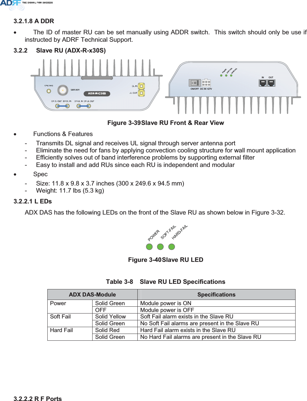
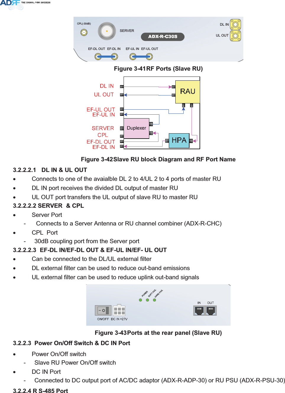
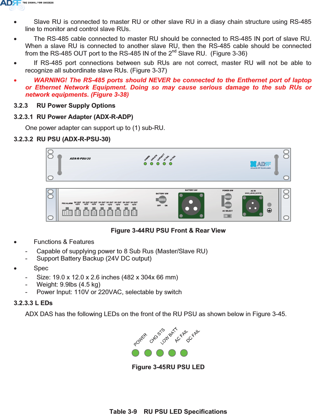
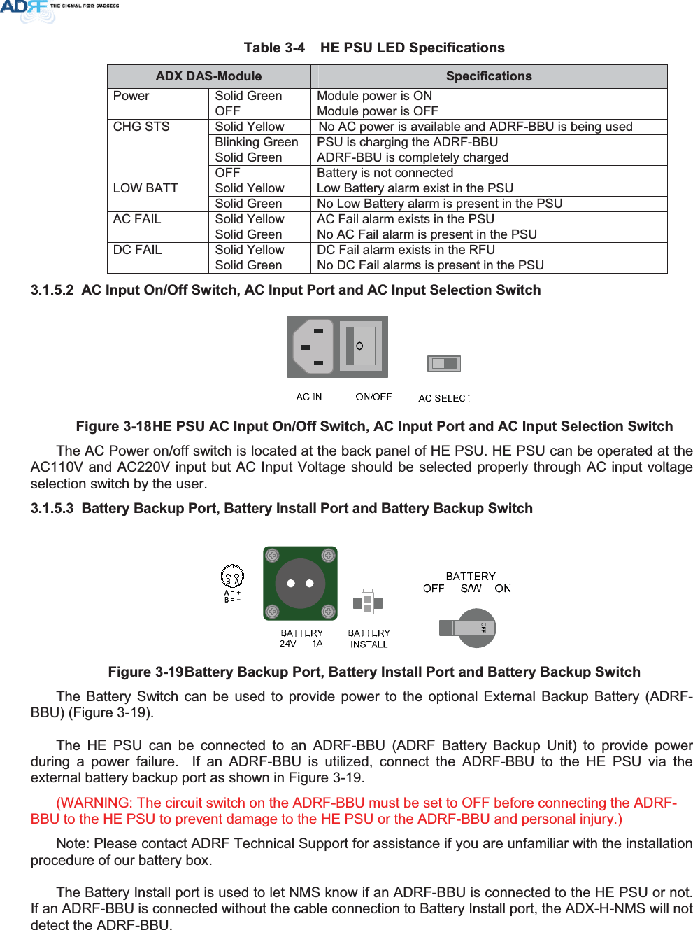
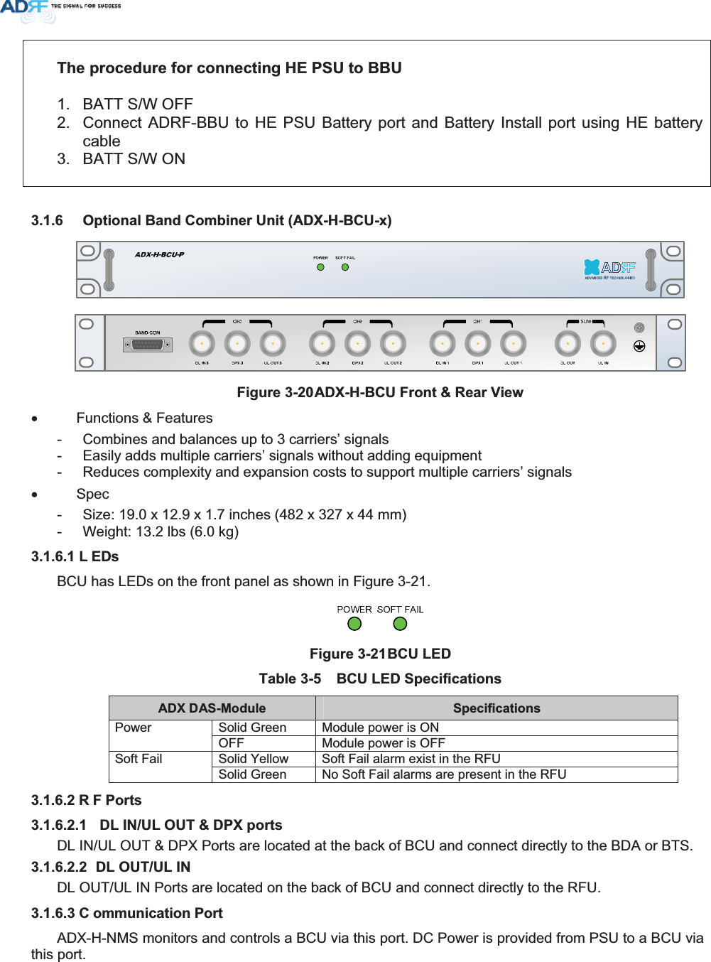
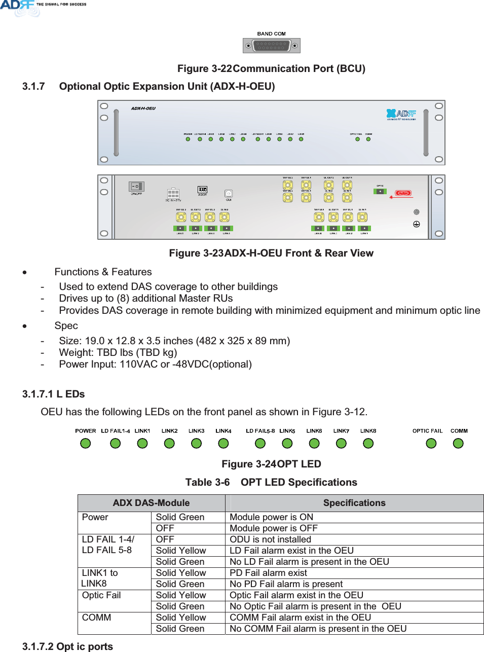
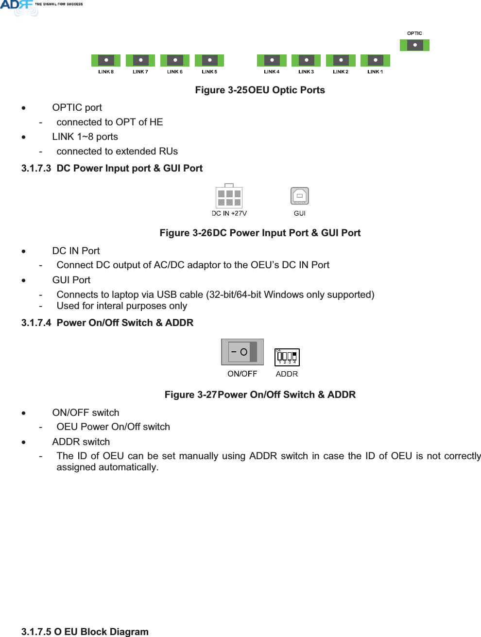
Advanced RF Technologies ADX-R-C30S DAS(Distributed Antenna System) User Manual ADX DAS V0 3
Advanced RF Technologies, Inc. DAS(Distributed Antenna System) ADX DAS V0 3
UserManual.wiki
>
Advanced RF Technologies
>
ADX R C30S User Manual
TempConfidential_ADX-R-C30S_User Manual-rev.-pdf - -
Navigation menu
Upload a User Manual
Namespaces
Wiki Guide
HTML
PDF
Info
Views
User Manual
Discussion / Help
Navigation

![: DUQLQJVDQG+D]DUGV/LWKLXP%DW WHU\ &$87,215,6 .2)(;3/2 6,21,)% $77(5<,6 5(3/$&('%< ,1&255(&77<3(',6326(2)86('%$77(5,(6$&&25',1*72,16758&7,2162SHQLQJRUWDPSHULQJWKH$';'$6ZLOOYRLGDOOZDUUDQWLHV:$55$17<$FWXDOVHSDUDWLRQGLVWDQFHLVGHWHUPLQHGXSRQJDLQRIDQWHQQDXVHG3OHDVHPDLQWDLQDPLQLPXPVDIHGLVWDQFHRIDWOHDVWGFPZKLOHRSHUDWLQJQHDUWKHGRQRUDQGWKHVHUYHUDQWHQQDV$OVRWKHGRQRUDQWHQQDQHHGVWREHPRXQWHGRXWGRRUVRQDSHUPDQHQWVWUXFWXUH5)(;32685($17(11$3/$&(0(17*XLGHOLQHV:RUNLQJZLWKWKH$';'$6ZKLOHLQRSHUDWLRQPD\H[SRVHWKHWHFKQLFLDQWR5)HOHFW URPDJQHWLF ILHOGV WKDWH[FHHG)&&UXOHVIR U KXPDQH[SRV XUH 9LVLW WKH)&&Z HEVLWH DW ZZZIFFJRYRHWUIVDIHW\ WR OH DUQPRUH DERXWWK HHIIHFW VRI H[SRVXUHWR5)HOHFWURPDJQHWLFILHOGV:$51,1*(;32685(725)2SHQLQJWKH$';'$6 FRXOGUHVXOWLQ HOHFWULFVKRFNDQGPD\FDXVHVHYHUHLQMXU\:$51,1*(/(&75,&62&](https://usermanual.wiki/Advanced-RF-Technologies/ADX-R-C30S/User-Guide-1702950-Page-21.png)
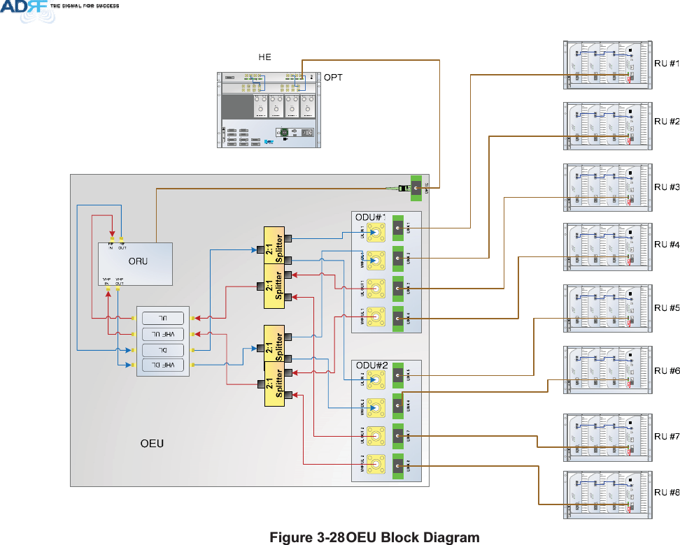
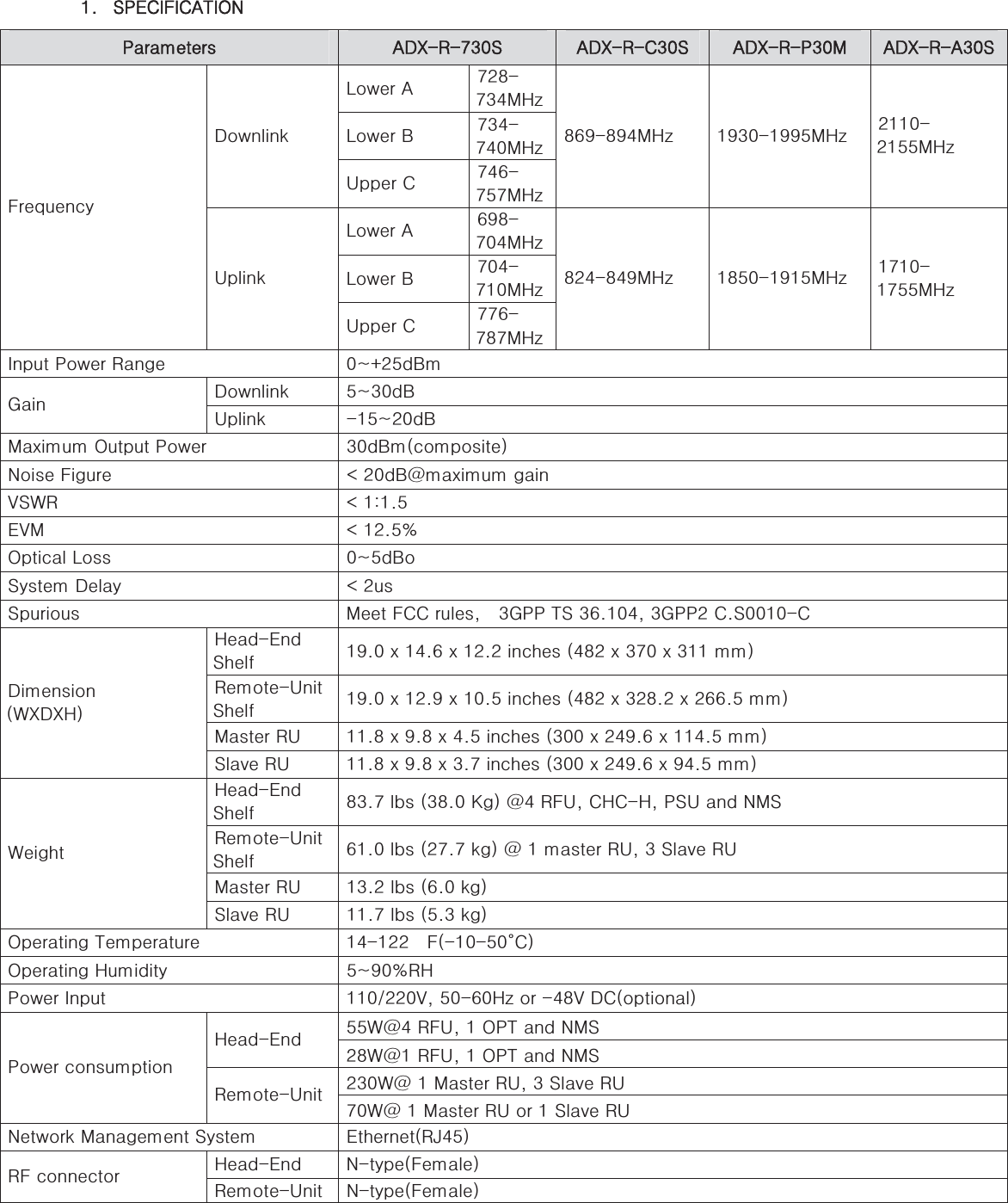
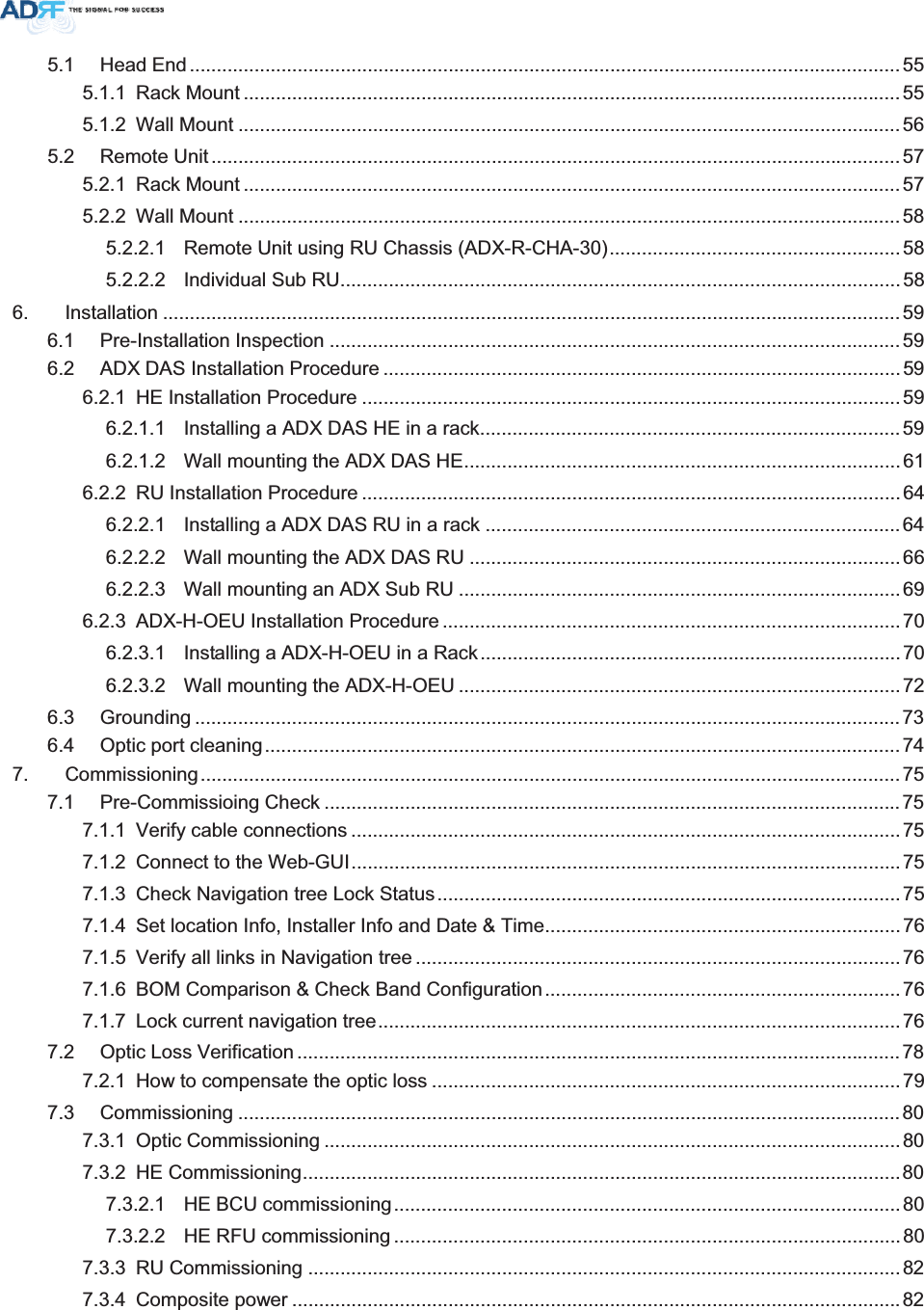
![5 8$';5[06RU is composed of a (1) Master RU and up to (7) Slave RU’s (use the use of ADX-R-4WS). A power supply, either the ADX-R-ADP (supports [1] Master/Slave RU) or ADX-R-PSU-30 (supports up to [8] Master/Slave RU) is required. x Spec - Size: 19.0 x 12.9 x 10.5 inches (482 x 328.2 x 266.5 mm) - Weight: 61.0 lbs (27.7 kg) - Power Input: 110VAC or -48VDC(optional) - Battery Backup supported )LJXUH58)URQW9LHZPOWERSOFTFAILHARDFAILPOWERSOFTFAILHARDFAILPOWERSOFTFAILHARDFAILPOWERSOFTFAILHARDFAILCOMMOPTICFAIL)LJXUH585HDU9LHZ](https://usermanual.wiki/Advanced-RF-Technologies/ADX-R-C30S/User-Guide-1702950-Page-38.png)