Advanced RF Technologies AXIOM Modular RF Repeater (Bi-Directional Amplifier) User Manual
Advanced RF Technologies, Inc. Modular RF Repeater (Bi-Directional Amplifier)
Users Manual
Axiom Repeater
USER MANUAL
Version 0.3
3116 Vanowen St.
Burbank, CA 91505
Tel: 818-840-8131
Fax: 818-840-8138
www.adrftech.com

Axiom Repeater
User Manual V0.3
Page | 2
Glossary
The following is a list of abbreviations and terms used throughout this document.
Abbreviation/Term Definition
AGC Automatic Gain Control
ALC Automatic Level Control
AROMS ADRF’ Repeater Operation and Management
System
BTS Base Transceiver Station
CDMA Code Division Multiple Access
CFE Compact Front End
CW Continuous Wave (un-modulated signal)
DAS Distributed Antenna System
DL Downlink
Downlink The path covered from the Base Transceiver
Station (BTS) to the subscribers service area via
the repeater
HPA High Power Amplifier
HW Hardware
IF Intermediate Frequency
LNA
LTE
Low Noise Amplifier
Long Term Evolution
MS Mobile Station
PLL Phased Locked Loop
PS Power Supply
RF Radio Frequency
SQE Signal Quality Estimate
SW Software
UL Uplink
Uplink The path covered from the subscribers service
area to the Base Transceiver Station(BTS) via the
repeater
VSWR Voltage Standing Wave Ratio
Axiom Repeater
User Manual V0.3
Page | 3
Released version: 0.3
Information in this document is subject to change without notice.
Advanced RF Technologies, Inc. 1996-2010.
All rights reserved.
Please send comments to:
E-Mail: info@adrftech.com
Phone: (818) 840-8131
(800) 313-9345
Fax: (818) 840-8138
Address: Advanced RF Technologies, Inc.
Attention: Technical Publications Department
3116 Vanowen St.
Burbank, CA 91505
USA
www.adrftech.com
Revision History
Version Author Description Date
0.1 YH Ko Initial Release Dec 29, 2009
0.3 Sun Kim Format and content updates Feb 9, 2010

Axiom Repeater
User Manual V0.3
Page | 4
TABLE OF CONTENTS
1. AXIOM REPEATER ........................................................................................................ 6
1.1 Introduction ............................................................................................................... 6
1.1.1 Highlights ........................................................................................................ 6
1.1.2 Parts List ......................................................................................................... 7
1.1.3 Repeater Quick View ...................................................................................... 8
2. WARNINGS AND HAZARDS ........................................................................................ 9
3. AXIOM OVERVIEW ..................................................................................................... 11
3.1 Switches & Fault Indicators .................................................................................... 11
3.1.1 MCU LEDs ................................................................................................... 11
3.1.2 RFU LEDs .................................................................................................... 12
3.1.3 Alarms ........................................................................................................... 13
3.2 Switches and Ports .................................................................................................. 15
3.2.1 Power Switch ................................................................................................ 15
3.2.2 Back Up Battery Switch & Battery Port ....................................................... 15
3.2.3 External Modem and Ethernet Port ............................................................... 16
3.2.4 RF Ports ........................................................................................................ 16
3.3 Modular concept ...................................................................................................... 17
3.3.1 System modular concept ............................................................................... 17
3.3.2 Band (RFU) modular concept ....................................................................... 17
3.3.3 Combining method of the various optional configuration ............................ 18
3.4 Power supply architecture ....................................................................................... 20
3.5 Installation ............................................................................................................... 20
3.5.1 Procedure ...................................................................................................... 20
3.5.2 Grounding ..................................................................................................... 23
3.5.3 Antenna Separation/Isolation ........................................................................ 24
3.5.4 Line of Sight ................................................................................................. 25
4. AXIOM WEB-GUI SETUP ........................................................................................... 26
4.1 Repeater/PC Connection Using Web-GUI .............................................................. 26
4.2 Status Tab ................................................................................................................ 27
4.2.1 Status: Axiom-xx-700 ................................................................................... 28
4.2.2 Status: Axiom-xx-C ...................................................................................... 29
4.2.3 Status: Axiom-xx-P ....................................................................................... 29
4.2.4 Status: Axiom-xx-A ...................................................................................... 30
4.3 Control Tab .............................................................................................................. 31
4.3.1 Control: Axiom-xx-700 ................................................................................. 35
4.3.2 Control: Axiom-xx-C .................................................................................... 35
4.3.3 Control: Axiom-xx-P .................................................................................... 36
4.3.4 Control: Axiom-xx-A .................................................................................... 36
4.4 Install Tab ................................................................................................................ 37
4.4.1 Install: Axiom-xx-700 ................................................................................... 37
4.4.2 Install: Axiom-xx-C ...................................................................................... 38

Axiom Repeater
User Manual V0.3
Page | 5
4.4.3 Install: Axiom-xx-P ....................................................................................... 38
4.4.4 Install: Axiom-xx-A ...................................................................................... 39
4.5 System ..................................................................................................................... 40
4.5.1 System: Firmware Update............................................................................. 40
4.5.2 System: Account Management ..................................................................... 40
4.5.3 System: New Account ................................................................................... 41
4.5.4 System: Administrator .................................................................................. 41
4.6 Help ......................................................................................................................... 42
4.7 Logout ..................................................................................................................... 42
5. MAINTENANCE GUIDE FOR AXIOM REPEATER .............................................. 43
5.1 Periodic Inspection Checklist .................................................................................. 43
5.2 Preventive Measures for Optimal Operation ........................................................... 43
5.2.1 Recommendations ......................................................................................... 43
5.2.2 Precautions .................................................................................................... 43
6. WARRANTY AND REPAIR POLICY ......................................................................... 44
6.1 General Warranty .................................................................................................... 44
6.2 Limitations of Warranty .......................................................................................... 44
6.3 Limitation of Damages ............................................................................................ 44
6.4 No Consequential Damages .................................................................................... 44
6.5 Additional Limitation on Warranty ......................................................................... 44
6.6 Return Material Authorization (RMA) .................................................................... 44
7. APPENDIX A: SPECIFICATIONS .............................................................................. 45
Electrical Specifications ................................................................................................ 45
APPENDIX B: MECHANICAL DRAWING ................................................................... 47
APPENDIX C: AXIOM OVERVIEW .............................................................................. 48
C.1 System Block Diagram ........................................................................................... 48
C.2 Components ............................................................................................................ 49
APPENDIX D: SHUTDOWN RETRY LOGIC .............................................................. 51

Axiom Repeater
User Manual V0.3
Page | 6
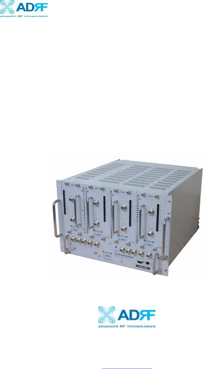
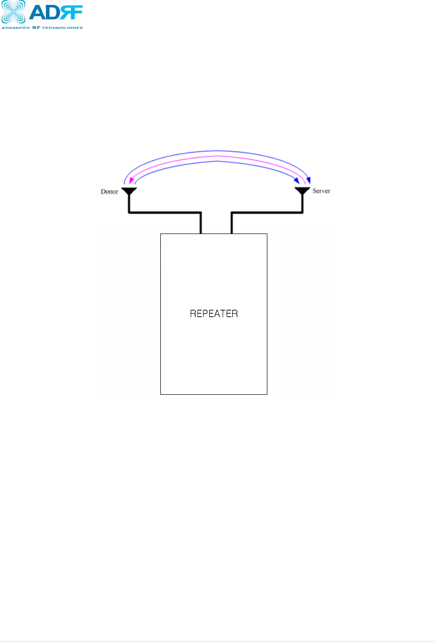
1. Axiom Repeater
1.1 Introduction
Four technologies in one body: Axiom is an over-the-air repeater system that can
incorporate up to 4 technologies in one body. Current supported technologies are
LTE, Cellular, PCS and AWS band.
1.1.1 Highlights
• Can utilize up to 4 technologies simultaneously
o Covers the LTE band
10MHz upper C block, 5MHz lower A block and 5MHz lower B
block (Add Lower A+B)
o Covers the 60 MHz PCS band
Three independent RF PCS channels, each channel supports
1.25 MHz to 18.75 MHz bandwidth
o Covers the 25MHz Cellular band
o Covers the 45 MHz AWS band
• 25K/100K/Large Composite Output Power [24/30/43 dBm]
• 30 dB AGC Range @ 0.5 dB Step
• Adjustable AGC Output Power Level
• Band Selectable via Web-GUI
• Can Support Non-Contiguous Bands
• Supports Embedded Wireless Modem
• Supports Network Management Monitoring System via SNMP
• Adjustable FA (3 channels)
• Digital filtering
• Incremental Automatic Shutdown/Resumption Time: Axiom gradually increases
the time span between automatic shutdown and resumption before it
permanently shuts itself down
• AI compatible: Axiom is fully compatible with Applied Innovation’s monitoring
system.
• Versatility and Usability: Axiom gives total control to the user. Most of the
control parameters, e.g., gain, output power, alarm threshold, etc. can be
changed using the Web-GUI so that the user can adjust the system perfectly to
the given RF environment
• Web-GUI connectivity via DHCP
• Supports DHCP; No 3rd party GUI software required
• Automated installation
Axiom Repeater
User Manual V0.3
Page | 7
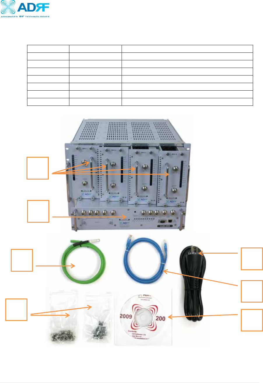
1.1.2 Parts List
Label Quan
t
ity Description
A 1 Axiom Network Management System (NMS)
B Up to 4* Optional Axiom Modules*
C 1 AC Power Cable
D 1 Ethernet Cable (Crossover)
E 1 Documentation CD**
F 1 Ground Cable
G 8 Rack Mount Bolt/Nu
t
* At least 1 module must be present in order to use Axiom
** CD includes: User Manual, Quick-Start Guide, and Troubleshooting Guide
Figure A – Axiom Repeater Parts List
Table 1 – Parts List
A
B
C
D
E
F
G
Axiom Repeater
User Manual V0.3
Page | 8
1.1.3 Repeater Quick View
Ground Hole
(Page 17)
LED indicator
(Page 12)
Modem
19” Rack
mount Holes
(Page 16)
RFU
MCU
Battery
switch
(Page 14)
Power switch
(Page 14)
AC Power
Inlet
(Page 14)
Battery port
(Page 14)
110/220 Selector
(Page 14)
Axiom Repeater
User Manual V0.3
Page | 9
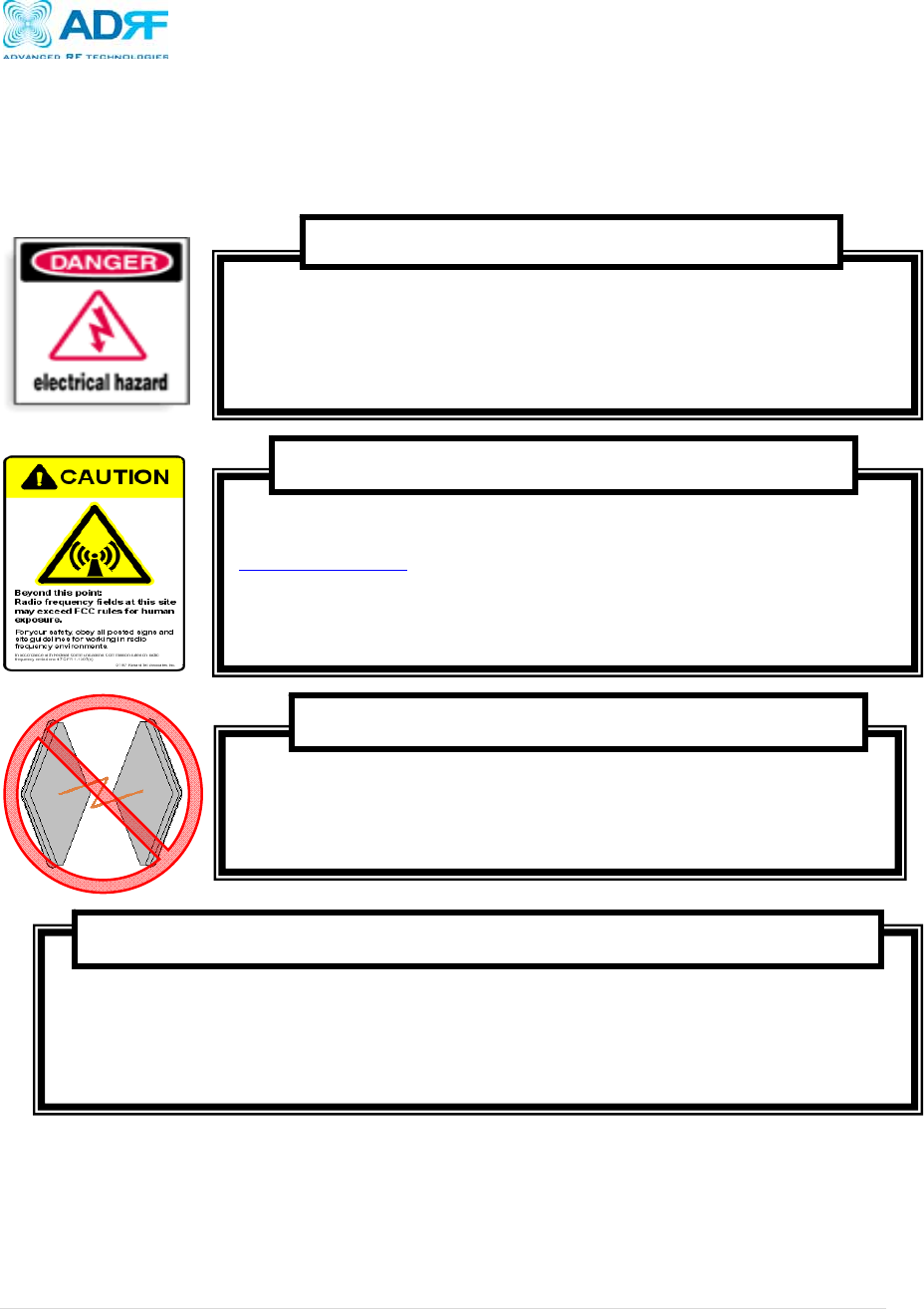
2. Warnings and Hazards
Actual separation distance is determined upon gain of antenna used.
Please maintain a minimum safe distance of at least 20 cm while operating near the donor and the server antennas. Also,
the donor antenna needs to be mounted outdoors on a permanent structure.
RF EXPOSURE & ANTENNA PLACEMENT Guidelines
Operating the Axiom with antennas in very close proximity facing each other could lead to
severe damage to the repeater.
WARNING! DAMAGE TO REPEATER
Working with the repeater while in operation, may expose the technician to RF electromagnetic
fields that exceed FCC rules for human exposure. Visit the FCC website at
www.fcc.gov/oet/rfsafety to learn more about the effects of exposure to RF electromagnetic
fields.
WARNING! EXPOSURE TO RF
Opening the Axiom could result in electric shock and may cause severe
injury.
WARNING! ELECTRIC SHOCK

Axiom Repeater
User Manual V0.3
Page | 10
NOTE: This equipment has been tested and found to comply with the limits for a Class
A digital device, pursuant to part 15 of the FCC Rules. These limits are designed to
provide reasonable protection against harmful interference when the equipment is
operated in a commercial environment. This equipment generates, uses, and can
radiate radio frequency energy and, if not installed and used in accordance with the
instruction manual, may cause harmful interference to radio communications.
Operation of this equipment in a residential area is likely to cause harmful interference
in which case the user will be required to correct the interference at their own
expense.
FCC Part 15 Class A
Lithium Battery: CAUTION. RISK OF EXPLOSION IF BATTERY IS REPLACED BY INCORRECT
TYPE. DISPOSE OF USED BATTERIES ACCORDING TO INSTRUCTIONS.
Ethernet Instructions: This equipment is for indoor use only. All cabling should be limited
to inside the building.
Opening or tampering the Axiom will void all warranties.
WARRANTY
Axiom Repeater
User Manual V0.3
Page | 11
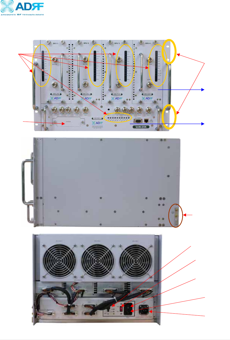
3. Axiom Overview
3.1 Switches & Fault Indicators
3.1.1 MCU LEDs
Figure 1: MCU LED
PWR(POWER)
Parameters Specifications
LED Repeater On Solid Green LED On
Repeater Off LED Off
AC Fail
Parameters Specifications
LED Normal LED Off
Ha
r
d fail Solid Red LED On
Condition for Alarm Activation AC fail
DC Fail
Parameters Specifications
LED Normal LED Off
Hard fail Solid Red LED on
Condition for Alarm Activation DC fail
After Alarm Activation Full Spectrum shutdown
TAMP (Tamper detected)
Parameters Specifications
LED Normal Solid Green LED On
Soft fail Solid Red LED On
Condition for Alarm Activation Controlling Key parameter in normal operation
Alarm Clear Cleared by an authorized user
RMF 1,2,3,4 (Replaceable module failure)
Parameters Specifications
LED Normal Solid Green LED On
Hard fail Solid Red LED On
Condition for indication RFU Module failure per band
RESET (Reset engaged)
Parameters Specifications
LED Normal Solid Green LED On
Soft fail Solid Red LED On
Condition for Alarm Activation Control of Software Reset
Alarm Clear Cleared by an authorized user
BATT(Battery)
Parameters Specifications
LED Charging Solid Red LED On
Full charged Solid Green LED On
Batt S/W off or
non- connection
LED Off
Axiom Repeater
User Manual V0.3
Page | 12
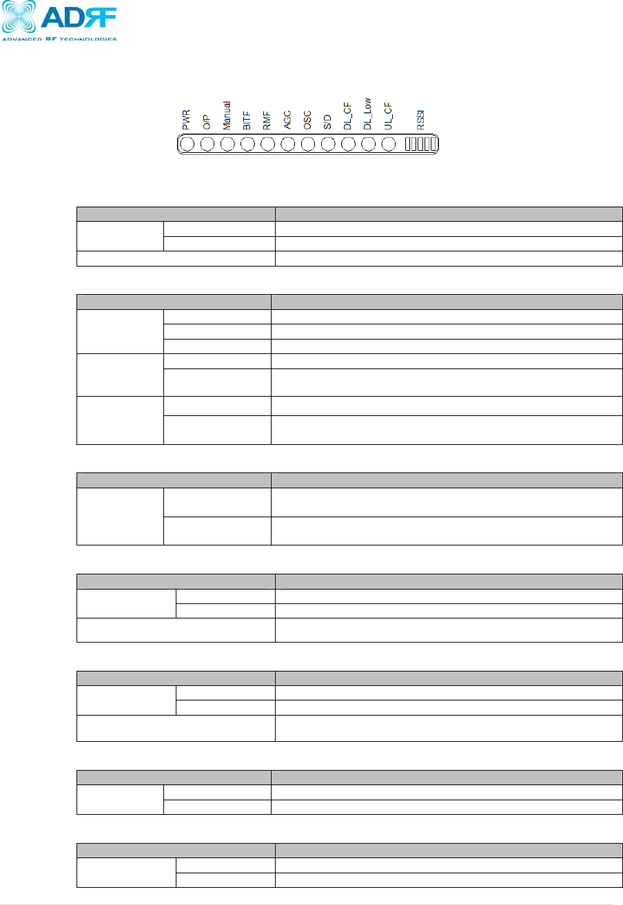
3.1.2 RFU LEDs
Axiom has LEDs on the front panel of the repeater as shown below in Figure 2.
Figure 2: RFU LED
PWR (RFU Power)
Parameters Specifications
LED Normal Blinking Green LED
Alarm Solid Red LED on
Condition for Alarm Activation Power fail
O/P (Over Power)
Parameters Specifications
LED
Normal Solid Green LED On
Soft fail Blinking Red LED
Hard fail Solid Red LED On
Condition for
Alarm
Activation
Soft fail Max power +1 <measured output < max power+2
Hard fail measured output > max power + 2
Following
Alarm
Activation
Soft fail Only the alarm is activated and the repeater operates as normal
Hard fail The function associated with the alarm shutdown, and the
shutdown process goes into effect
Manual
Parameters Specifications
LED
Manually HPA
Off/On PCS (Cellular) Green LED On
Factory set or
Reboot PCS (Cellular) Green LED Off
BITF (Built-in test failure)
Parameters Specifications
LED Normal Solid Green LED on
Hard fail Solid Red LED on
Condition for indication RFU Module built-in test failure
RMF (Replaceable module failure)
Parameters Specifications
LED Normal Solid Green LED On
Hard fail Solid Red LED On
Condition for indication RFU Module failure
AGC (AGC active)
Parameters Specifications
LED AGC On Solid Green LED On
AGC Off LED Off
OSC (Oscillation detected)
Parameters Specifications
LED Normal Solid Green LED On
Hard fail Solid Red LED On
Axiom Repeater
User Manual V0.3
Page | 13
Condition for Alarm Activation Repeater goes into oscillation
Following Alarm Activation The portion associated with the oscillation shuts down, and at
time of oscillation the defined procedure goes into effect
S/D (Shutdown)
Parameters Specifications
LED Normal Solid Green LED on
Hard fail Solid Red LED on
Condition for Alarm Activation Overpower, Oscillation
DL_CF (Donor circuitry failure)
Parameters Specifications
LED Normal Solid Green LED On
Hard fail Solid Red LED On
Condition for indication RFU Module Donor circuitry failure
DL_Low (Donor power too low)
Parameters Specifications
LED Normal Solid Green LED On
Hard fail Solid Red LED On
Condition for indication Donor input level under threshold
UL_CF (Coverage circuitry failure)
Parameters Specifications
LED Normal Solid Green LED On
Hard fail Solid Red LED On
Condition for indication RFU Module coverage circuitry failure
RSSI (DL RSSI LED bar)
Parameters Specifications
LED Input < -95dBm Zero (0) bar On
Input < -85dBm One (1) bar On
Input < -75dBm Two (2) bars On
Input < -65dBm Three (3) bars On
Input < -55dBm Four (4) bars On
Input > -55dBm Five (5) bars On
3.1.3 Alarms
Parameters Remark
Tamper Temper detected
AC fail Power supply out of range
DC fail Power supply out of range
Communication failure Internal Communication failure
RMF Field replaceable module failure
RESET Reset alarm
Heartbeat Heartbeat
OSC Oscillation detected
UL RSSI fail Power at coverage port too high
UL PLL fail UL Synthesizer failure
H/W fail Hardware failure
S/W fail Software failure
UL Emission fail UL Out-of-band emissions out of spec
DL RSSI fail Donor Power too high/low

Axiom Repeater
User Manual V0.3
Page | 14
ISO fail Low isolation
DL PLL fail DL Synthesizer failure
DL Spur fail DL Spurious emissions out of spec
Interfere Interferer power exceeded
Axiom Repeater
User Manual V0.3
Page | 15
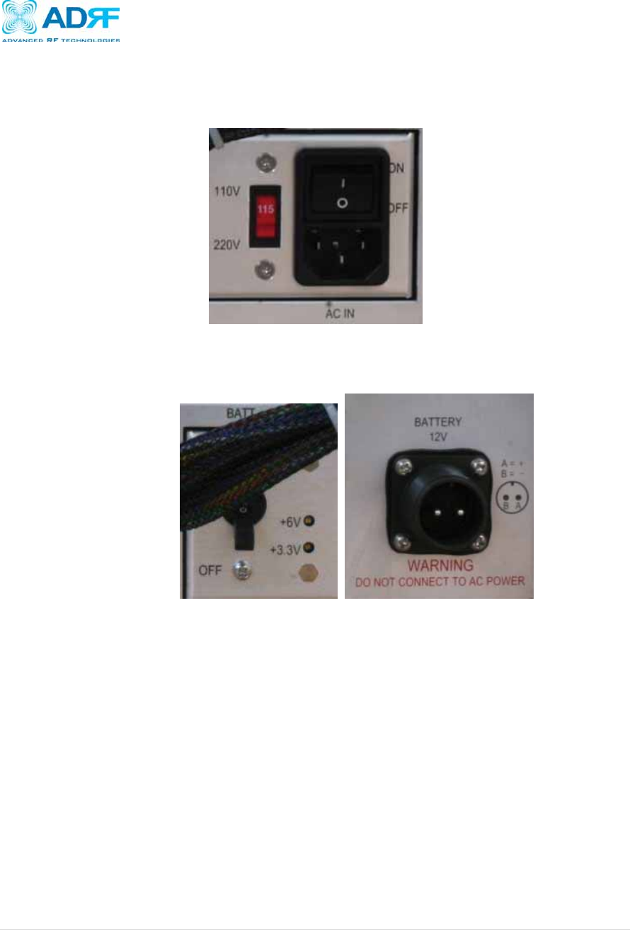
3.2 Switches and Ports
3.2.1 Power Switch
The AC Power on/off switch is located at the back panel of repeater. The switch
should be powered on after the repeater has been installed properly.
Figure 3: Axiom Repeater Power Switch View
3.2.2 Back Up Battery Switch & Battery Port
Figure 4: Battery Switch & Battery Port
The Battery Switch can be used to provide power to the optional External Backup
Battery.
If a backup battery is utilized, please connect the battery to the unit via the
external battery port as shown in Figure 4.
(WARINING: If the Circuit Protector Switch is not turned OFF there may be a risk
of damage or electric shock)
Note: Please contact ADRF Technical Support for assistance if you are
unfamiliar with the installation procedure of our battery box.
Axiom Repeater
User Manual V0.3
Page | 16
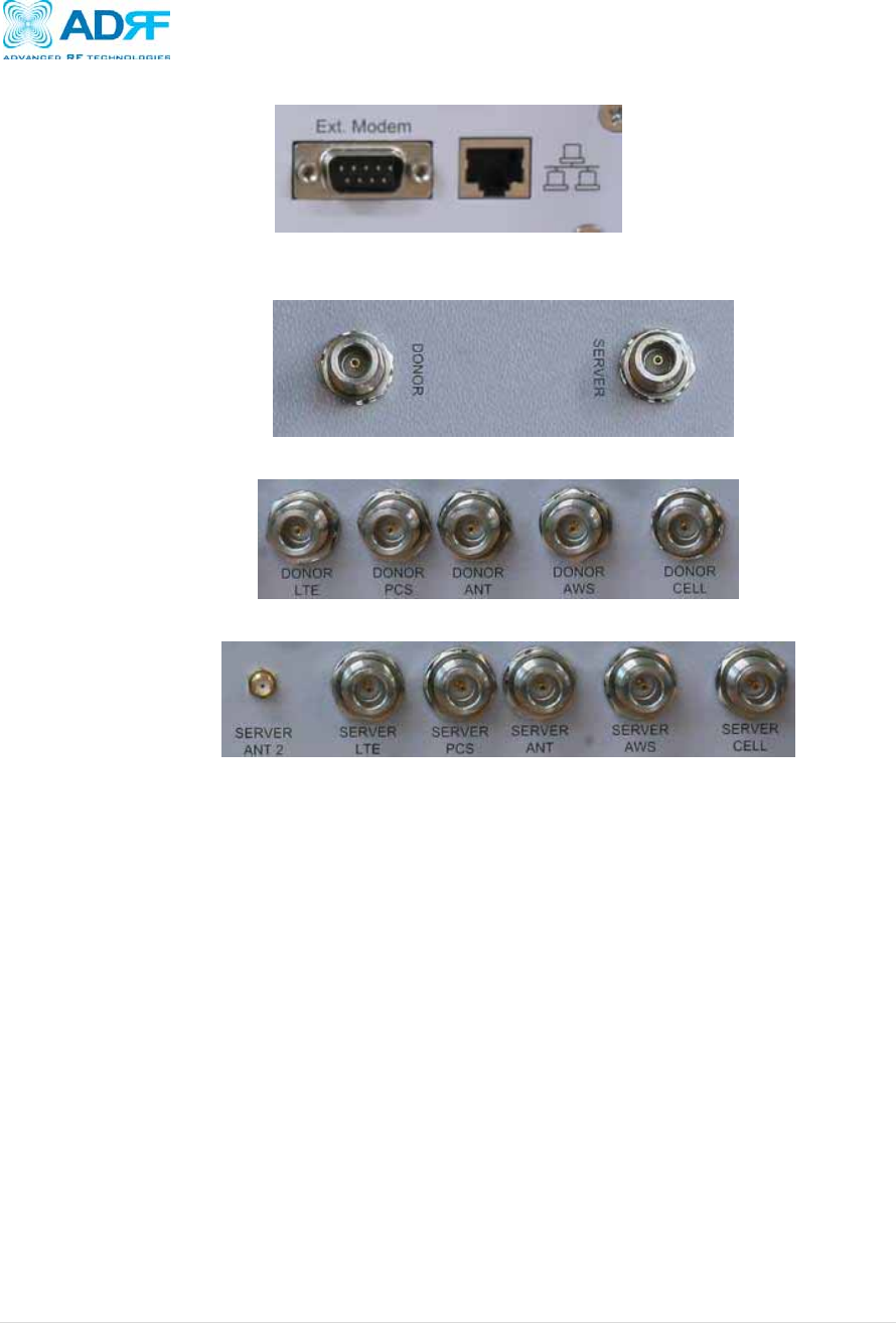
3.2.3 External Modem and Ethernet Port
Figure 5: External Modem and Ethernet Port
3.2.4 RF Ports
Figure 6: RFU RF port
Figure 7: Donor Combiner RF port
Figure 8: Server Combiner RF port
Donor(RFU):
o DL input port/UL output port, connected to Donor Antenna or Combiner’s Donor
port (Donor Combiner is optional)
Server(RFU)
o UL input port/DL output port, connected to Server Antenna or Combiner’s
Server port (Server Combiner is optional)
Server ANT 2
o For use with an auxiliary Server Antenna. Signal is attenuated by -15dB
compared to Server Combiner’s Server port.
Donor Combiner’s Donor port
o Application for multi-band combining to 1 Ant Donor port.
Sever Combiner’s Sever port
o Application for multi-band combining to 1 Ant Server port.
Axiom Repeater
User Manual V0.3
Page | 17
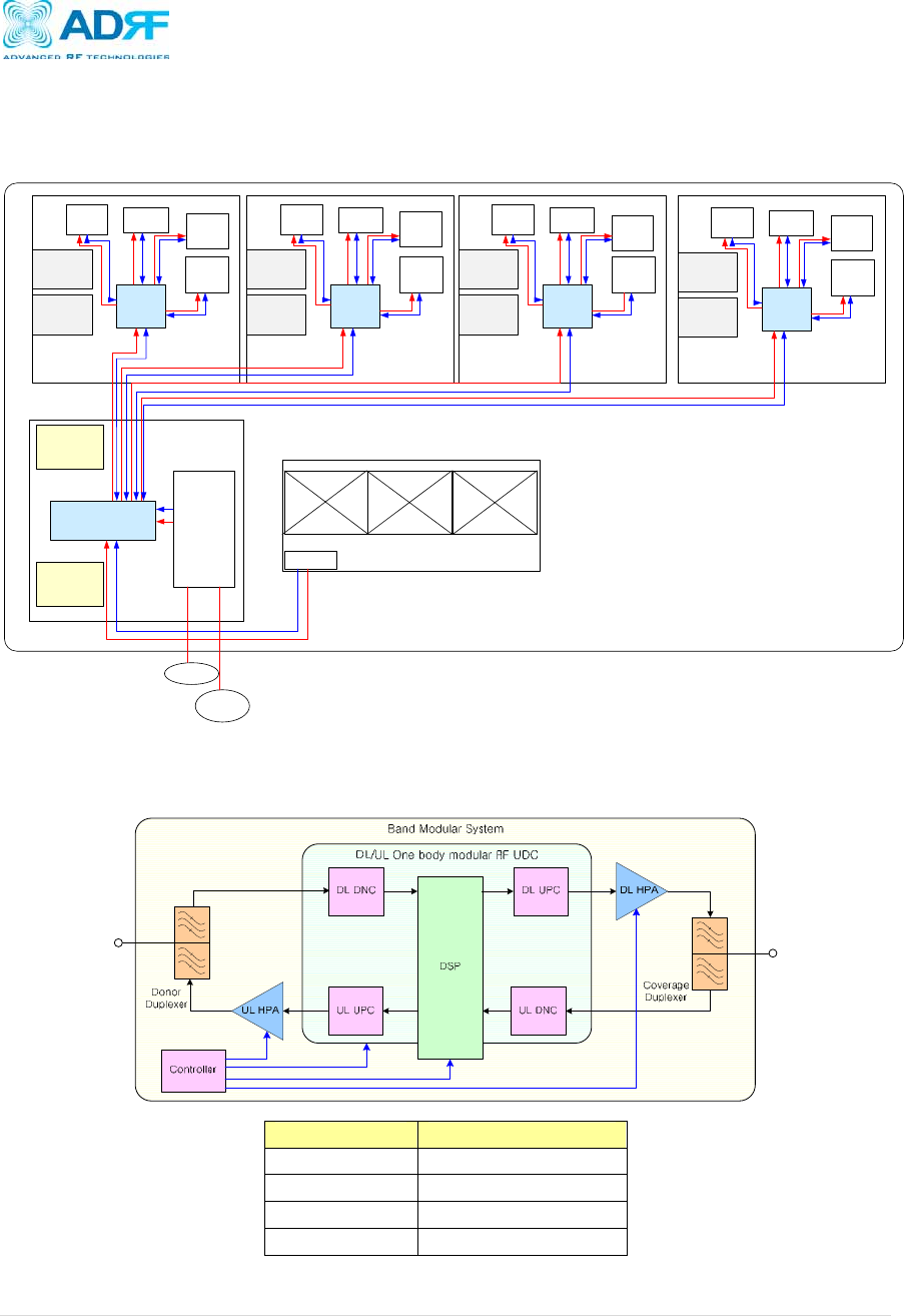
3.3 Modular concept
3.3.1 System modular concept
RFU1
MCU
UDC
DSP
DL
Duplexer
UL
Duplexer
UL
HPA
LTE
band
Control
Donor
Combiner
(Option)
PSU
AC-DC
Main
Control
RFU2
UDC
DSP
DL
Duplexer
UL
Duplexer
UL
HPA
Cellular
band
Control
RFU3
UDC
DSP
DL
Duplexer
UL
Duplexer
UL
HPA
PCS
band
Control
RFU4
UDC
DSP
DL
Duplexer
UL
Duplexer
UL
HPA
AWS
band
Control
FAN UNIT
FAN3FAN1 FAN2
FAN drive, alarm
AC
BATT
12V
DL
HPA
DL
HPA DL
HPA
DL
HPA
Coverage
Combiner
(Option)
Figure 9: System modular concept block diagram
3.3.2 Band (RFU) modular concept
Figure 10: Band (RFU) modular concept block diagram
Part Name BAND
RFU 1 LTE
RFU 2 Cellular
RFU 3 PCS
RFU 4 AWS
Axiom Repeater
User Manual V0.3
Page | 18
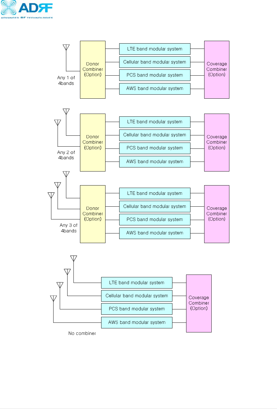
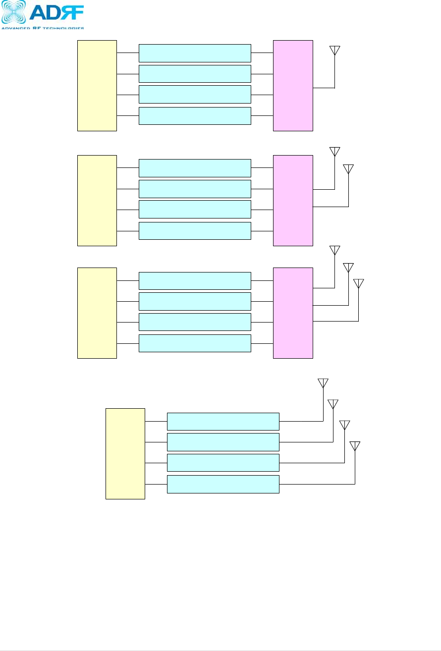
3.3.3 Combining method of the various optional configuration
Figure 11: Donor combining method by selection of various optional donor combiner
Axiom Repeater
User Manual V0.3
Page | 19
Coverage
Combiner
(Option)
LTE band modular system
Cellular band modular system
PCS band modular system
AWS band modular system
Donor
Combiner
(Option)
Coverage
Combiner
(Option)
LTE band modular system
Cellular band modular system
PCS band modular system
AWS band modular system
Donor
Combiner
(Option)
Coverage
Combiner
(Option)
LTE band modular system
Cellular band modular system
PCS band modular system
AWS band modular system
Donor
Combiner
(Option)
LTE band modular system
Cellular band modular system
PCS band modular system
AWS band modular system
Donor
Combiner
(Option)
Any 1 of
4bands
Any 2 of
4bands
Any 3 of
4bands
No combiner
Figure 12: Coverage combining method by selection of various optional coverage combiner
Axiom Repeater
User Manual V0.3
Page | 20
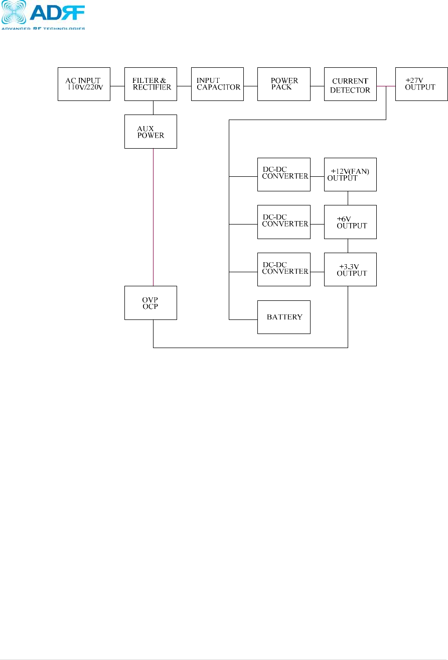
3.4 Power supply architecture
Figure 13: Power supply architecture
3.5 Installation
3.5.1 Procedure
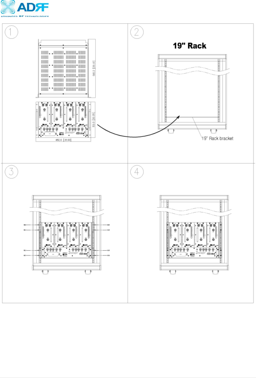
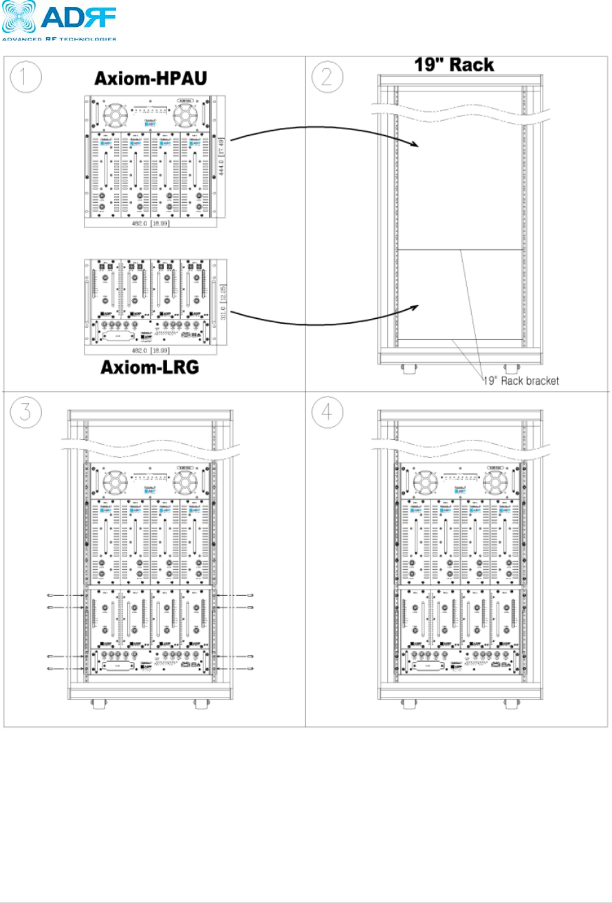
Eight mounting holes are located on 4 corners of repeater to attach it to the 19”
rack. The repeater must be securely attached to a rack mount system that can
sufficiently carry the weight of the Axiom.
The following steps should be followed while mounting the repeater:
Installation Procedure
① Verify that the repeater and mounting hole are in good condition.
② Align the repeater to the mounting holes of the rack mount system.
③ Screw the repeater to the rack using 8 mounting screws.
④ Make sure the Repeater is securely attached.
⑤ Connect the GND cable.
⑥ Connect the Antenna cable.
⑦ Connect the Power.
⑧ Using a laptop, install the Repeater.
Axiom Repeater
User Manual V0.3
Page | 21
Figure 14: Axiom-25/100 Mounting Instructions
Axiom Repeater
User Manual V0.3
Page | 22
Figure 15: Axiom-LRG Mounting Instructions
Axiom Repeater
User Manual V0.3
Page | 23
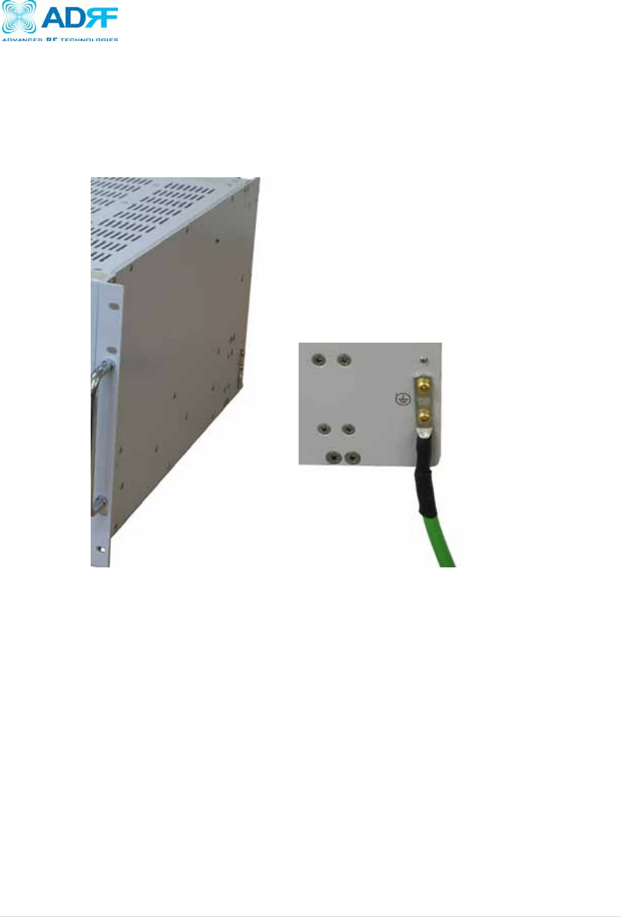
3.5.2 Grounding
A ground cable is included in the box. The ground cable should be connected to
the Right side of Axiom before the repeater is turned on.
Figure 16: Ground Cable Connection
Axiom Repeater
User Manual V0.3
Page | 24
3.5.3 Antenna Separation/Isolation
Separation between the antennas is necessary to prevent oscillation. Oscillation
occurs when the signal entering the system continually reenters, due to the lack of
separation between the donor and server antennas. In other words, the signal is
being fed back into the system. This creates a constant amplification of the
same signal. As a result, the noise level rises above the signal level.
Figure 17: RF Repeater Oscillation
To prevent feedback, the donor and server antennas must be separated by an
appropriate distance to provide sufficient isolation. Isolation is attained by
separating antennas a sufficient distance so that the output of one antenna does
not reach the input of the other. This distance is dependent on the gain of the
repeater.
A sufficient isolation value is 13 ~ 15 dB greater than the maximum gain of the
repeater. For example, if the gain of the repeater is 50 dB, then an isolation of 63
~ 65 dB or greater is required. In the same manner, because the Axiom has a
maximum gain of 80 dB in case of Axiom 25K, it requires an isolation of at least
93 ~ 95 dB.
Axiom Repeater
User Manual V0.3
Page | 25
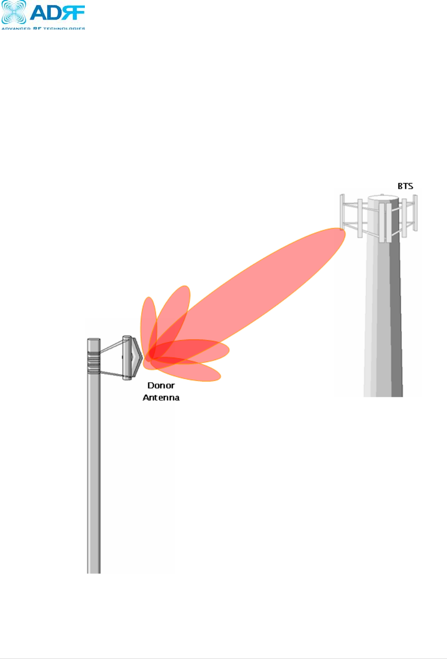
3.5.4 Line of Sight
The donor antenna which points towards the base station typically has a narrow
beam antenna pattern. As a result, a slight deviation away from the direction of the
BTS can lead to less than optimum results. In addition, obstacles between the
repeater and the BTS may impair the repeater from obtaining any BTS signal. As a
result, the repeater cannot transmit signal to the coverage area. Therefore, a
direct line of sight to the BTS for the donor antenna is vital to the function of a
repeater. For the same reason, placing the server antenna in direct line of sight
of the coverage area is also necessary.
Figure 17 - Direct Line of Sight to the BTS
Axiom Repeater
User Manual V0.3
Page | 26
4. Axiom Web-GUI Setup
The Web-GUI allows the user to communicate with the repeater either locally or remotely. To
connect to the repeater locally, you will need a laptop with an Ethernet port and a RJ-45
crossover cable. To connect to the repeater remotely, you will need to have an active internet
connection and the repeater must have either an internal modem or an Omnibox (ADRF Modem
Box) connected to the repeater.
4.1 Repeater/PC Connection Using Web-GUI
A. Verify that your Local Area Connection is set to Obtain an IP address automatically
under the Internet Protocol (TCP/IP) properties
If you are connecting to the unit remotely, then skip steps A and B.
B. Connect the RJ-45 crossover cable between the laptop’s Ethernet port and the
repeater’s Ethernet port
C. Launch Microsoft Internet Explorer (Version 7.0 or below)
D. Type the following IP address into the address bar of Microsoft Internet Explorer:
http://192.168.63.1
If you are connecting to the unit remotely, then type the IP address of the modem to
connect to the unit
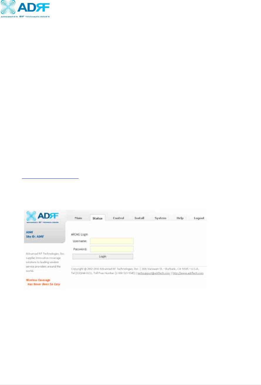
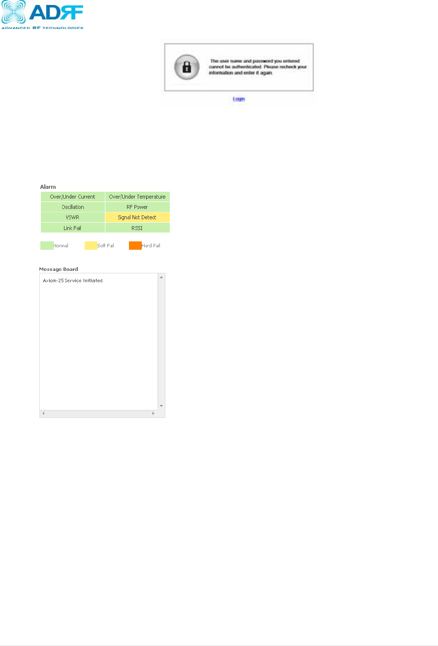
E. The following login screen will appear:
If you are not the Administrator, please type in your assigned username & password
which you should have received from the Administrator.
The default username and password for the General User is adrf & adrf, respectively.
If the username & password is typed in incorrectly, the following screen will appear:
Axiom Repeater
User Manual V0.3
Page | 27
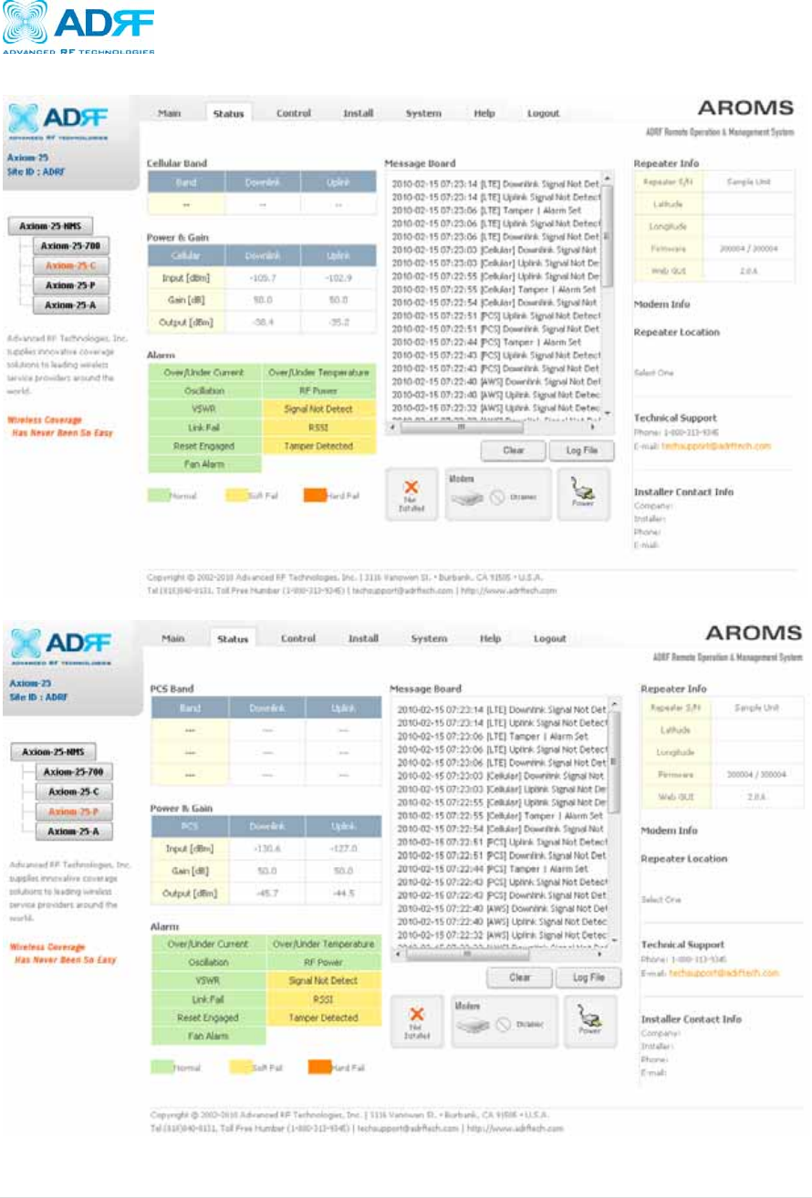
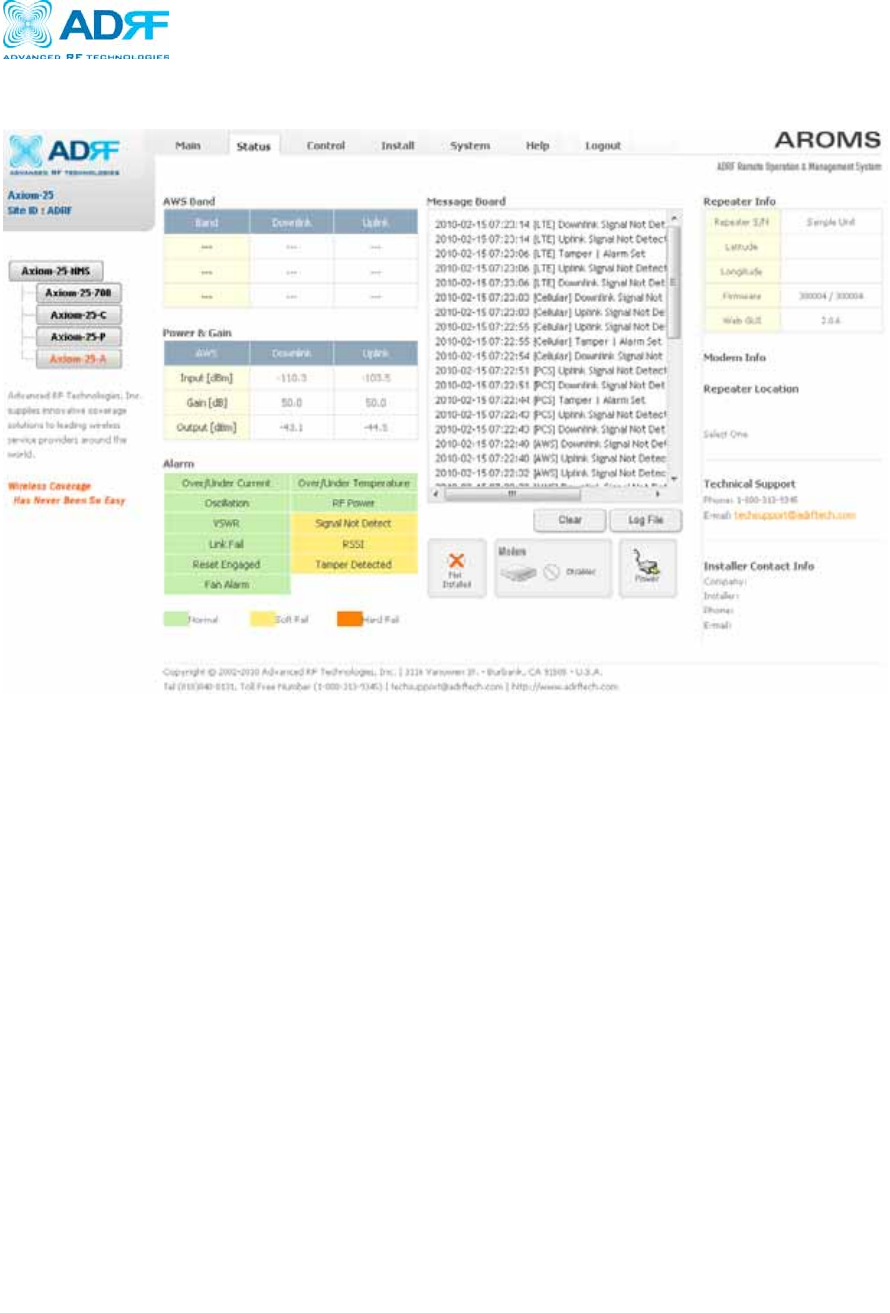
4.2 Status Tab
Band: Displays the bands that are currently being utilized
Power & Gain: Displays the Input, Gain, and Output for both Downlink and Uplink
Alarm: Displays eight (8) alarms with three different status conditions (Normal, Soft Fail
or Hard Fail).
Message Board: Displays the 20 most recent events.
Clear: Clears the content that is currently being displayed on the Message Board
Log File: Downloads the system Log File (events and alarms) to your computer
Alarm History: Downloads the Alarm History log (alarms only) to your computer
Installation: Displays whether or not the installation routine has been run (Not Installed
or Installed)
Modem: Displays the status of the modem
o Disabled- No internal modem is present
o Not Connected- Internal modem is detected, but no connection to the network
has been established
o Connected- Internal modem is detected and a connection to the network has
been established
Repeater Info: Displays the serial number, latitude, longitude, firmware version, Web-
GUI version
Modem Info: Displays the ESN (DEC), MDN, and IP Address of the internal modem
Repeater Location: Displays the address where the repeater is installed
Technical Support: Displays ADRF’s Technical Support contact information
Axiom Repeater
User Manual V0.3
Page | 28
Installer Contact Info: Displays the installer’s name, phone and e-mail address
Note: Once successfully logged in, the repeater model name and the site/cascade
ID will be displayed on the top of all the windows (except for the Main Window).
4.2.1 Status: Axiom-xx-700
Axiom Repeater
User Manual V0.3
Page | 29
4.2.2 Status: Axiom-xx-C
4.2.3 Status: Axiom-xx-P
Axiom Repeater
User Manual V0.3
Page | 30
4.2.4 Status: Axiom-xx-A
Axiom Repeater
User Manual V0.3
Page | 31
4.3 Control Tab
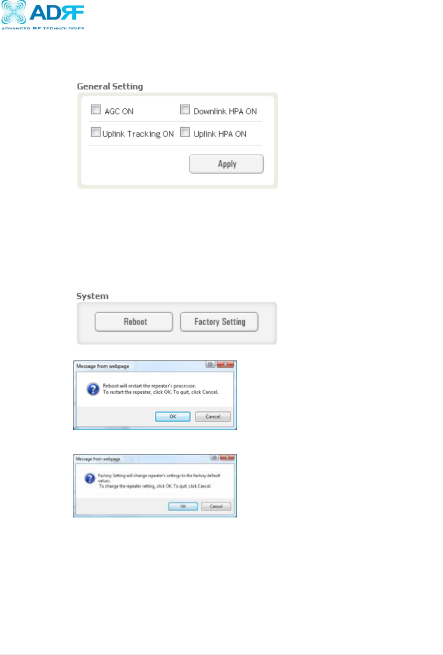
General Setting
o AGC ON: Enables or disables AGC (Automatic Gain Control)
o Uplink Tracking ON: Enables or disables the Uplink Tracking Feature
Uplink Tracking adjusts the Uplink Gain to meet the Uplink Tracking Offset
value
o Downlink HPA ON: Enables or disables the DL HPA
o Uplink HPA ON: Enables or disabled the UL HPA
System
o Reboot: Clicking the reboot button will have the following popup show up:
Click OK to reboot the repeater or click Cancel to exit out
o Factory Setting: Resets the repeater to the original factory settings
Axiom Repeater
User Manual V0.3
Page | 32
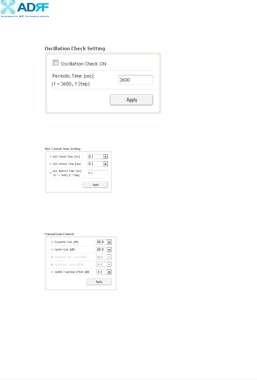
Oscillation Check Setting
o Oscillation Check ON: Enables or disables oscillation check
o Periodic Time: Allows the use to specify how often the repeater runs the
oscillation check
AGC Control Time Setting
o AGC Check Time: The frequency at which the system checks the AGC level
o AGC Attack Time: Time it takes to lower the gain to match the AGC level
o AGC Release Time: Time it takes to raise the gain to match the AGC level
Manual Gain Control
o Downlink Gain: Allows the DL gain to be adjusted manually when AGC is OFF
o Uplink Gain: Allows the UL gain to be adjusted manually when AGC is OFF
o Downlink AGC Level: Allows the user to set the DL gain when AGC is enabled
o Uplink AGC Level: Allows the user to set the UL gain when AGC is enabled
o Uplink Tracking Offset: This offset value determines how many dB lower the
uplink gain value will be relative to the downlink gain value

Axiom Repeater
User Manual V0.3
Page | 33
Main Gain Control Range
Control Modules 25K 100K Large Note
Downlink Gain - 50~80 60~90 65~95 0.5dB step, default:
Minimum Level
Uplink Gain - 50~80 60~90 65~95 0.5dB step, default:
Minimum Level
Downlink AGC Level
LTE &
CELL 15 ~ -14 25 ~ -4 38 ~ 8 0.5dB step, default:
Maximum Level
PCS &
AWS 20 ~ -9 30 ~ 0 43 ~ 13 0.5dB step, default:
Maximum Level
Uplink AGC Level
LTE &
CELL 15 ~ -14 25 ~ -4 25 ~ -4 0.5dB step, default:
Maximum Level
PCS &
AWS 20 ~ -9 30 ~ 0 30 ~ 0 0.5dB step, default:
Maximum Level
Uplink Tracking
Offset - 10 ~ 0 10 ~ 0 10 ~ 0 0.5dB step, default:
3dB
Oscillation & AGC time Control Range
Control Modules 25K 100K Large Note
Oscillation Period
time - 1~3600sec 1~3600sec 1~3600sec 1sec step, default:
3600sec
AGC Check Time - 0.1 ~ 1 sec 0.1 ~ 1 sec 0.1 ~ 1 sec Not use
AGC Attack Time - 0.1 ~ 1 sec 0.1 ~ 1 sec 0.1 ~ 1 sec Not use
AGC Release Time - 0.1 ~
3600sec 0.1 ~
3600sec 0.1 ~
3600sec 0.1 sec step, default:
0.1 sec
Alarm Control Range
Control Modules 25K 100K Large Note
Downlink Signal Low
Alarm - -30~-90 -30~-90 -30~-90 0.5dB step, default: -
85dB
Downlink Signal not
Detect Alarm - -80~-110 -80~-110 -80~-110 0.5dB step, default: -
85dB
Downlink RF Power
Alarm - 0 ~ 10 0 ~ 10 0 ~ 10 0.5dB step, default:
6dB
Uplink RF Power
Alarm - 0 ~ 10 0 ~ 10 0 ~ 10 0.5dB step, default:
6dB

Axiom Repeater
User Manual V0.3
Page | 34
Alarm Setting
o Downlink Signal Low: Allows the user to specify how weak the signal can be
before triggering a “Downlink Signal Low” soft-fail alarm
o Downlink Signal Not Detected: Allows the user to specify the how weak the
signal can be before triggering a “Signal Not Detected” soft-fail alarm
o Downlink RF Power: Allows the user to set a maximum deviation value for the
downlink RF power
For example, if the input signal is -50 dBm and the gain is set to 60 dB,
the expected output power should be 10 dBm. If the Downlink RF
Power alarm value is set to 6dB, then if the output power is below 4
dBm, then this will trigger a soft-fail alarm
o Uplink RF Power: Allows the user to set a maximum deviation value for the
uplink RF power
For example, if the input signal is -50 dBm and the gain is set to 60 dB,
the expected output power should be 10 dBm. If the Uplink RF Power
alarm value is set to 6dB, then if the output power is below 4 dBm, then
this will trigger a soft-fail alarm
o Reset Engaged: Allows the Reset Engaged functioned to be enabled or disabled
o Tamper Detected: Allows the tamper detection feature to be enabled or disabled
Axiom Repeater
User Manual V0.3
Page | 35
4.3.1 Control: Axiom-xx-700
4.3.2 Control: Axiom-xx-C
Axiom Repeater
User Manual V0.3
Page | 36
4.3.3 Control: Axiom-xx-P
4.3.4 Control: Axiom-xx-A
Axiom Repeater
User Manual V0.3
Page | 37
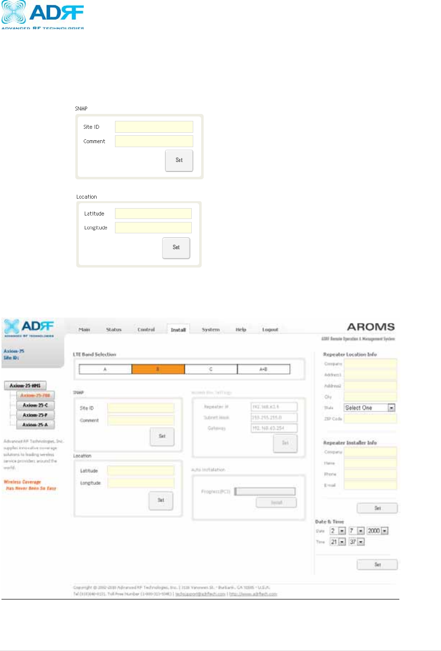
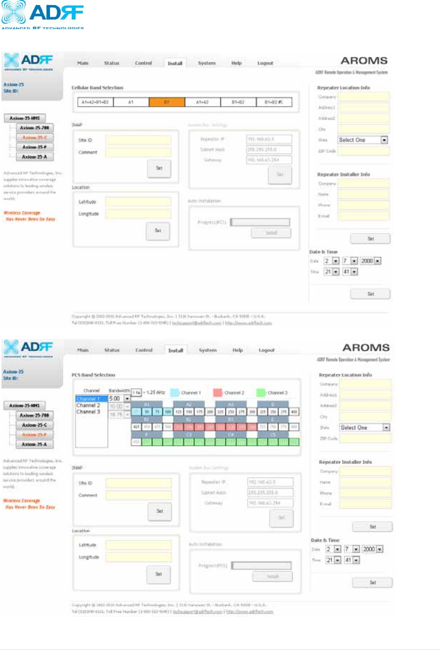
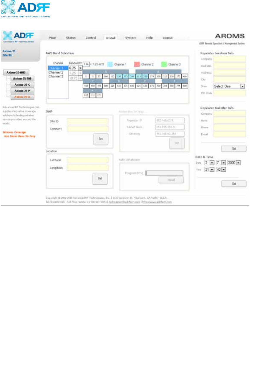
4.4 Install Tab
Band Selection: Allows the user to select the band(s) they would like to utilize
SNMP: Type in the assigned site/cascade ID and manager IP address. Default Site ID
and Manager IP address are ADRF and 100.10.10.100, respectively.
Location: Displays the physical address where the repeater is installed
Auto Installation: Runs the automated installation routine that will run basic checks to
ensure that the repeater can function in the environment
4.4.1 Install: Axiom-xx-700
Axiom Repeater
User Manual V0.3
Page | 38
4.4.2 Install: Axiom-xx-C
4.4.3 Install: Axiom-xx-P
Axiom Repeater
User Manual V0.3
Page | 39
4.4.4 Install: Axiom-xx-A
Axiom Repeater
User Manual V0.3
Page | 40
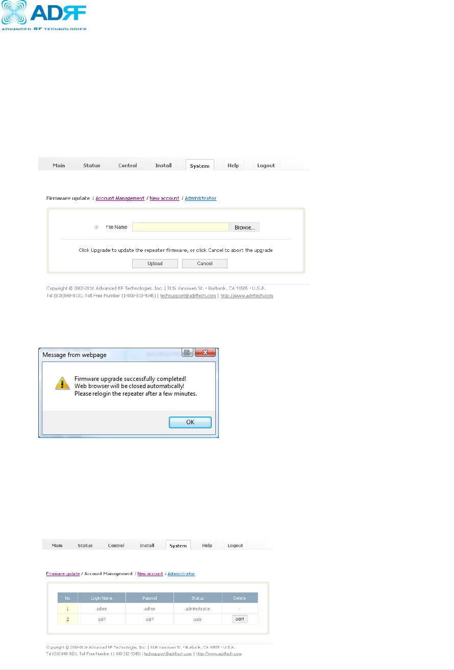
4.5 System
The System tab allows the user to perform firmware updates, add/remove user accounts, and
change the login credentials of the Administrator.
4.5.1 System: Firmware Update
To perform a firmware update, click on the System tab and the following screen will
show up.
Click on the Browse… button and locate the firmware file
Click on the Upload button to perform the firmware update
Once the firmware update is complete, the following popup message will appear:
4.5.2 System: Account Management
The Account Management section will allow the Administrator to delete any user
account. Please note that the Account Management section is only available if you
are logged into the system as the Administrator. To delete a user account click on the
Account Management link and under the Delete column, click on the delete button.
Axiom Repeater
User Manual V0.3
Page | 41
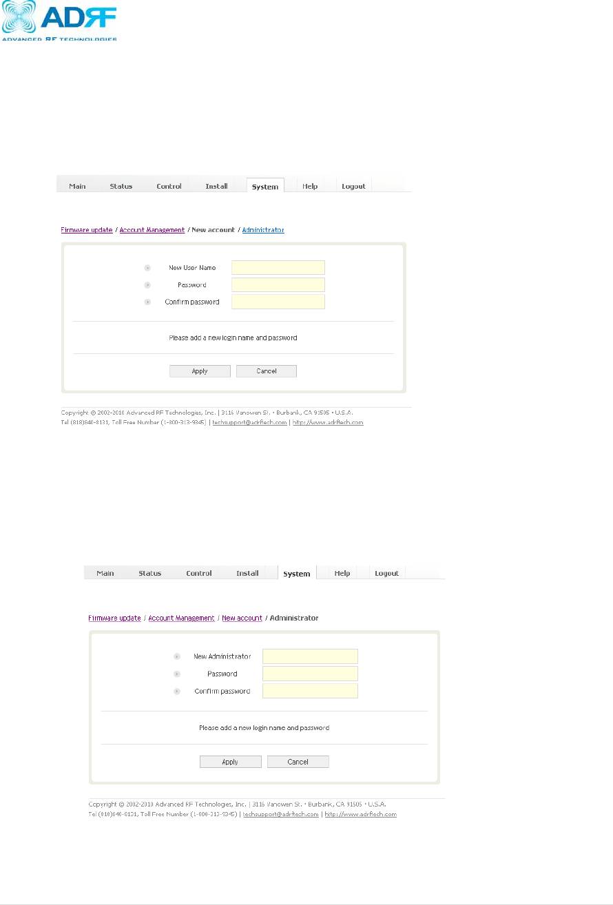
4.5.3 System: New Account
The New account section allows the Administrator to create a new user account.
Please note that the New account section is only available if you are logged into the
system as the Administrator. To create a new user account click on the New account
link and fill in the fields highlighted in yellow as shown below.
4.5.4 System: Administrator
The Administrator section allows the Administrator to change their login credentials.
Please note that the Administrator section is only available if you are logged into the
system as the Administrator. To change the login/password of the administrator, click
on the Administrator link and fill in the sections highlighted in yellow as shown below.

Axiom Repeater
User Manual V0.3
Page | 42
4.6 Help
If an internet connection is available, clicking on the Help Tab will redirect the user to our
Technical Support page.
4.7 Logout
Clicking the Logout button will log the current user off the system.

Axiom Repeater
User Manual V0.3
Page | 43
5. Maintenance Guide for Axiom Repeater
5.1 Periodic Inspection Checklist
a) Check for loose connections between the repeater and antennas. If connections are
loose, make sure that all connections are tightly fastened properly.
b) Cables and connectors are in good condition.
c) Ensure that the repeater brackets are in good. condition and that the repeater is
securely fastened
5.2 Preventive Measures for Optimal Operation
5.2.1 Recommendations
Perform the Periodic Inspection Checklist quarterly or semi-annually.
5.2.2 Precautions
Do not operate the repeater with the antennas in extremely close proximity to
one another as this may cause damage to the repeater.
Do not change the parameters unless instructed to do so by an authorized
supervisor.
Do not move the repeater unless instructed to do so by an authorized
supervisor.
Do not detach any cables to the repeater unless repair of respective
components is necessary.

Axiom Repeater
User Manual V0.3
Page | 44
6. Warranty and Repair Policy
6.1 General Warranty
The Axiom carries a Standard Warranty period of two (2) years unless indicated
otherwise on the package or in the acknowledgment of the purchase order.
6.2 Limitations of Warranty
Your exclusive remedy for any defective product is limited to the repair or replacement
of the defective product. Advanced RF Technologies, Inc. may elect which remedy or
combination of remedies to provide in its sole discretion. Advanced RF Technologies,
Inc. shall have a reasonable time after determining that a defective product exists to
repair or replace the problem unit. Advanced RF Technologies, Inc. warranty applies to
repaired or replaced products for the balance of the applicable period of the original
warranty or ninety days from the date of shipment of a repaired or replaced product,
whichever is longer.
6.3 Limitation of Damages
The liability for any defective product shall in no event exceed the purchase price for
the defective product.
6.4 No Consequential Damages
Advanced RF Technologies, Inc. has no liability for general, consequential, incidental or
special damages.
6.5 Additional Limitation on Warranty
Advanced RF Technologies, Inc. standard warranty does not cover products which have
been received improperly packaged, altered, or physically damaged. For example,
broken warranty seal, labels exhibiting tampering, physically abused enclosure, broken
pins on connectors, any modifications made without Advanced RF Technologies, Inc.
authorization, will void all warranty.
6.6 Return Material Authorization (RMA)
No product may be returned directly to Advanced RF Technologies, Inc. without first
getting an approval from Advanced RF Technologies, Inc. If it is determined that the
product may be defective, you will be given an RMA number and instructions in how to
return the product. An unauthorized return, i.e., one for which an RMA number has not
been issued, will be returned to you at your expense. Authorized returns are to be
shipped to the address on the RMA in an approved shipping container. You will be
given our courier information. It is suggested that the original box and packaging
materials should be kept if an occasion arises where a defective product needs to be
shipped back to Advanced RF Technologies, Inc. To request an RMA, please call
(800) 313-9345 or send an email to techsupport@adrftech.com.

Axiom Repeater
User Manual V0.3
Page | 45
7. Appendix A: Specifications
Electrical Specifications
Item Specification Remark
Frequency
700MHz
Upper C DL : 746~757MHz
UL : 776~787MHz
Lower A DL : 728~734MHz
UL : 698~704MHz
Lower B DL : 734~740MHz
UL : 704~710MHz
Cellular DL : 869~894MHz
UL : 824~849MHz
PCS DL : 1930~1990MHz
UL : 1850~1910MHz
AWS DL : 2110~2155MHz
UL : 1710~1755MHz
25K 100K Large
Output Power
PCS, AWS 20dBm 30dBm 43(DL)/30(UL)dB
m
700MHz,
CELL 15dBm 25dBm
38(DL)/25(UL)dB
m
Gain DL 80dB 90dB 95dB
UL 80dB 90dB 95dB
Gain control range 30dB(0.5dB step)
Input Power
DL -65~-35dBm -65~-35dBm -57~-27dBm
LTE& CELL
UL -65~-35dBm -65~-35dBm -57~-27dBm
DL -60~-30dBm -60~-30dBm -52~-22dBm
PCS& AWS
UL -60~-30dBm -60~-30dBm -52~-22dBm
Ripple ≤ 3dB ≤ 3dB ≤ 3dB
Spurious
700MHz Meet, FCC
Cellular
≤-46dBc/30KHz@±750KHz
≤-55dBc/30KHz@±1.98MHz
≥-13dBm/1MHz@±3.125MHz
PCS
≤-45dBc/30KHz@±885KHz
≤-50dBc/30KHz@±1.98MHz
≥-13dBm/1MHz@±2.25MHz
AWS
≤-45dBc/30kHz @±885KHz
≤-50dBc/30kHz @±1.98MHz
≥-13dBm/1MHz @±2.25MHz
NF ≤ 6dB ≤ 6dB ≤ 6dB
Delay ≤ 6us ≤ 6us ≤ 6us
MIMO Port Isolation 30dBc
Frequency 700MHz 150Hz

Axiom Repeater
User Manual V0.3
Page | 46
Stability Cellular 150Hz
PCS 300Hz
AWS 300Hz
Input VSWR DL ≤ 1:1.5
UL ≤ 1:1.5
EVM ≤ 12.5%
Filter Roll-Off
700MHz 50dBc @±1MHz
Cellular 30dBc @±0.5MHz, 50dBc @±1MHz
PCS 50dBc @±1MHz
AWS 50dBc @±1MHz
Power Source 110V/220V AC
Operating Temperature -5~50C
Operating Humidity 5~90%RH
Size
12.2" x 19" x 20"
inches
12.2" x 19" x
20" inches
12.2" x 19" x 20"
inches
17.5" x 19" x 20"
inches Large Only
Weight 130 lbs 130 lbs 130 lbs
130 lbs Large Only
Power Consume
60 W @ Per Band
Max
130 W @Per
Band Max
430 W @ Per Band
Max
250 W / Total
Band Max
500 W / Total
Band Max
1650 W / Total
Band Max
[1] 3GPP TR 21.905: "Vocabulary for 3GPP Specifications".
[2] 3GPP2 C.S0011-C Recommended Minimum Performance Standards for cdma2000 Spread
Spectrum Mobile Stations
[3] 3GPP2 C.S0010-C Recommended Minimum Performance Standards for cdma2000 Spread
Spectrum Base Stations
[4] 3GPP TS 36.104 3rd Generation Partnership Project; Technical Specification Group Radio
Access Network;
Evolved Universal Terrestrial Radio Access (E-UTRA); Base Station (BS) radio transmission and
reception Title 47, primarily sections 27 and 90, Title 47 section 27.53 part g
[5] 3GPP2 C.S0051.0 “Minimum Performance Standards for cdma2000 Repeaters” or latest
version.
Axiom Repeater
User Manual V0.3
Page | 47
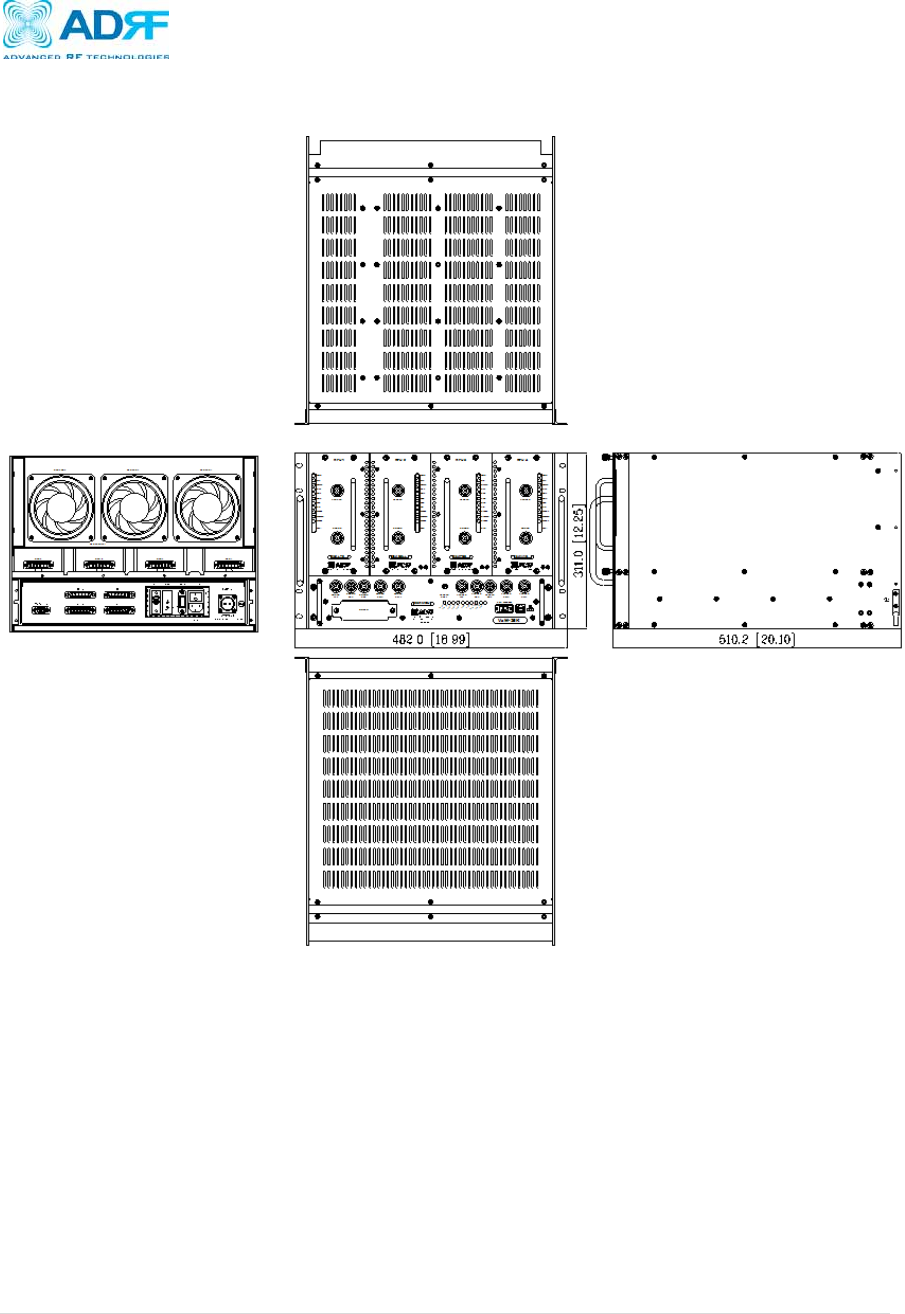
Appendix B: Mechanical Drawing
Figure 18: Axiom mechanical drawing
Axiom Repeater
User Manual V0.3
Page | 48
Appendix C: Axiom Overview
C.1 System Block Diagram
RFU1
MCU
UDC
DSP
DL
Duplexer
UL
Duplexer
UL
HPA
LTE
band
Control
Donor
Combiner
(Option)
PSU
AC-DC
Main
Control
RFU2
UDC
DSP
DL
Duplexer
UL
Duplexer
UL
HPA
Cellular
band
Control
RFU3
UDC
DSP
DL
Duplexer
UL
Duplexer
UL
HPA
PCS
band
Control
RFU4
UDC
DSP
DL
Duplexer
UL
Duplexer
UL
HPA
AWS
band
Control
FAN UNIT
FAN3FAN1 FAN2
FAN drive, alarm
AC
BATT
12V
DL
HPA
DL
HPA DL
HPA
DL
HPA
Coverage
Combiner
(Option)
Figure 19: System block diagram
Axiom Repeater
User Manual V0.3
Page | 49
C.2 Components
Figure 20: RFU 1, 2, 3, 4
Figure 21: MCU

Axiom Repeater
User Manual V0.3
Page | 50
Power Supply
It provides DC power to each module within the repeater.
Controller
It is responsible for monitoring the status of each module and controls the parameters.
PCS Up / Down Converter Module
The downlink RF signal that enters through the cavity filter is converted to IF frequency,
which is later converted back to RF frequency through SAW filtering.
Cellular Up / Down Converter Module
The downlink RF signal that enters through the cavity filter is converted to IF frequency,
which is later converted back to RF frequency through SAW filtering.
PCS Duplexer
It consists of two BPFs (band-pass filters): PCS TX (1930 ~ 1990 MHz) & RX (1850 ~
1910 MHz)
Triplexer
Combines Cellular and PCS signals. It consists of three BPFs (band-pass filters): PCS
and Cellular TX and RX.
Modem Module
Contains the CDMA 2000 modem (Kyocera M200).

Axiom Repeater
User Manual V0.3
Page | 51
Appendix D: Shutdown Retry Logic
The function of the built-in shutdown routine is to protect the repeater from any further damage
from a hard-fail that the system may be experiencing.
Within 5 seconds of a hard-fail alarm being detected, the repeater will start the shutdown
routine. The repeater will shut down by powering of the HPAs (high-powered amplifiers) for 30
seconds.
After 30 seconds have elapsed, the repeater will power on the HPAs and check to see if the
hard-fail alarm still exist. If the hard-fail alarm still exists, then the repeater will shut down for
1 minute (double the time of the previous shutdown time).
After 1 minute has elapsed, the repeater will power on the HPAs and check to see if the hard-
fail alarm still exist. If the hard-fail alarm still exists, then the repeater will shut down for 2
minutes (double the time of the previous shutdown time).
The shutdown routine will repeat itself a total of 10 times. If the hard-fail alarm still exists
after the 10th retry, then the repeater will turn on its HPAs permanently until a reset is
performed.