Advanced RF Technologies SDR-B Software Define Modular Repeater User Manual
Advanced RF Technologies, Inc. Software Define Modular Repeater Users Manual
UserManual.wiki
>
Advanced RF Technologies
>
SDR B User Manual
Users Manual
Navigation menu
Upload a User Manual
Namespaces
Wiki Guide
HTML
PDF
Info
Views
User Manual
Discussion / Help
Navigation
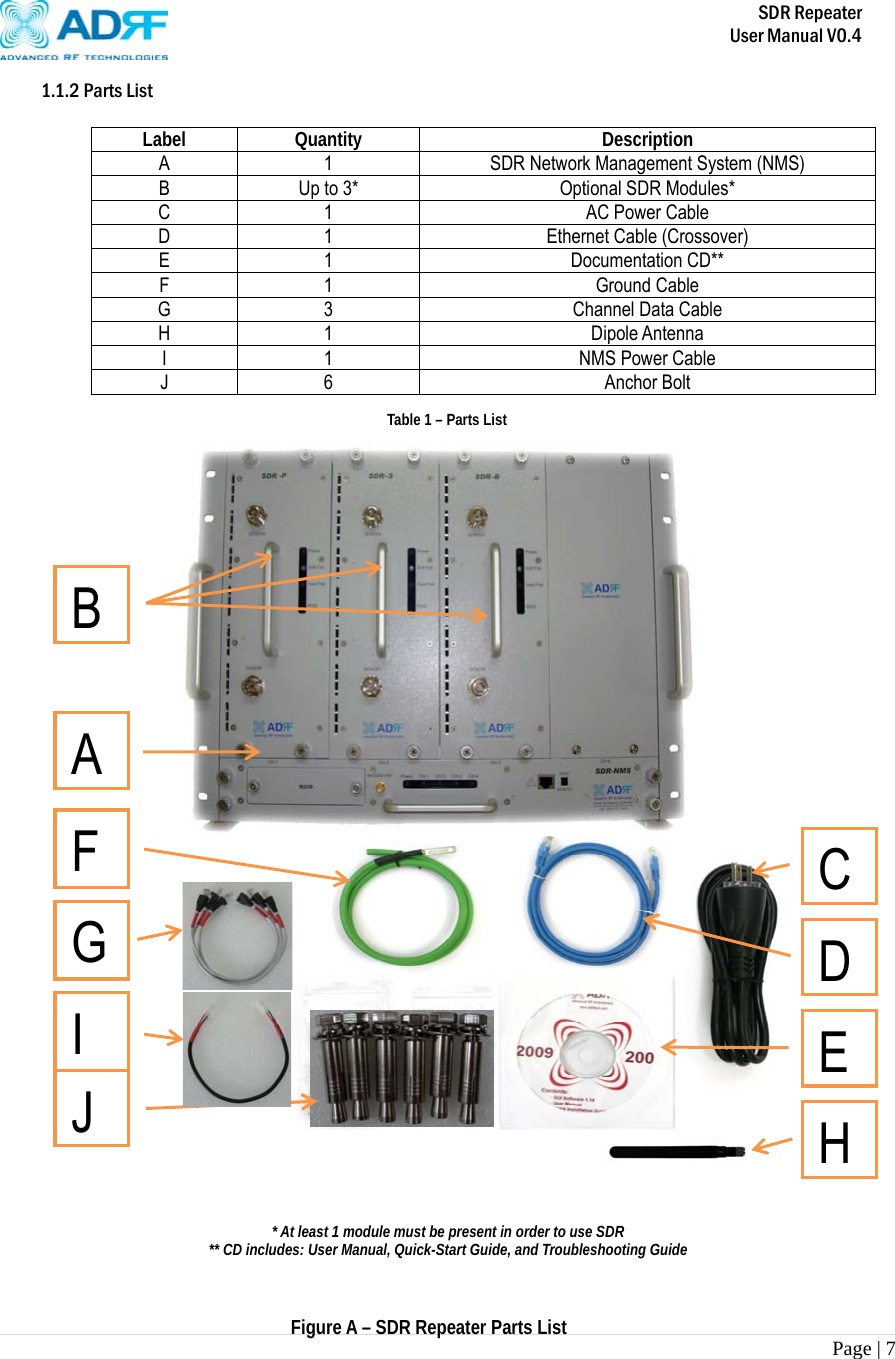
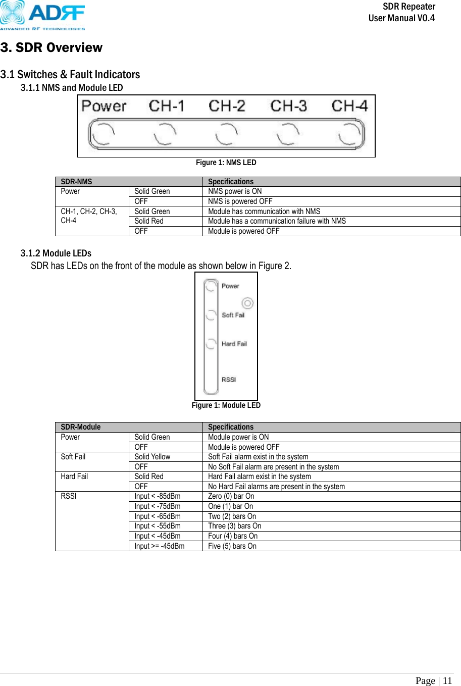
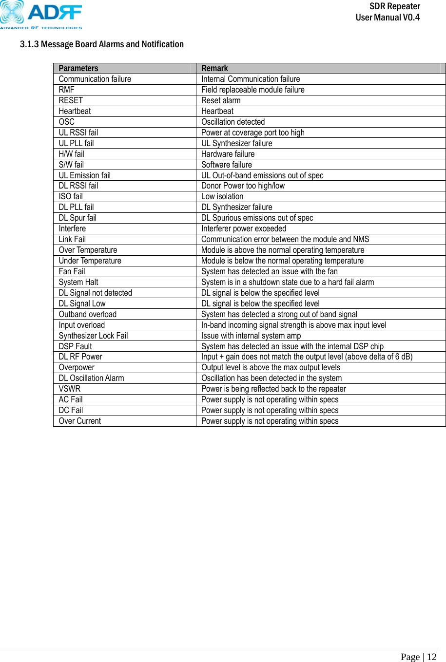
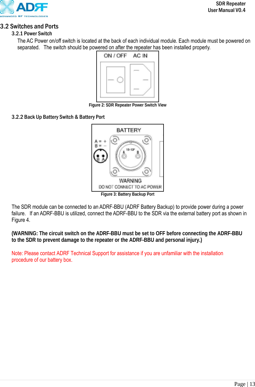
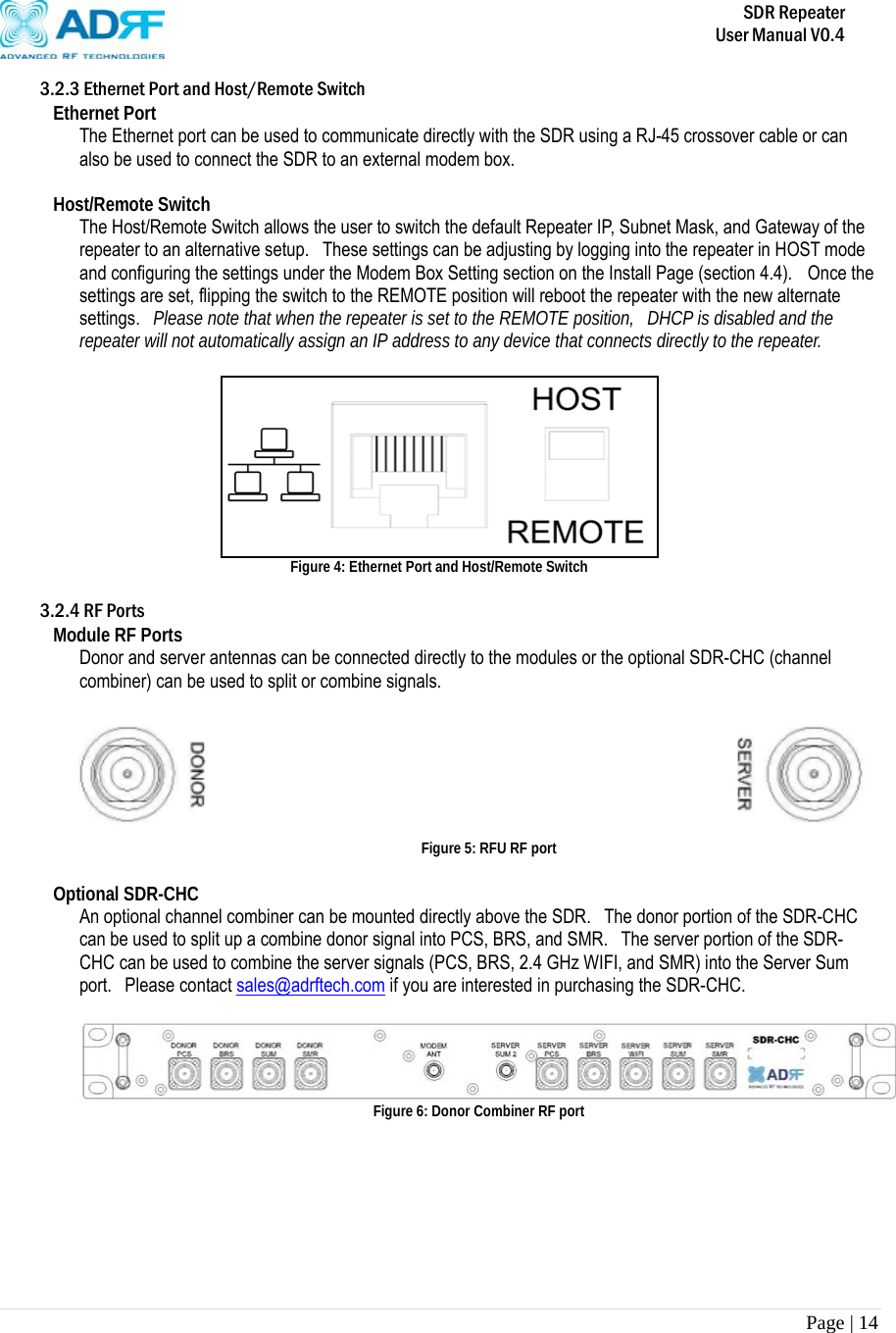
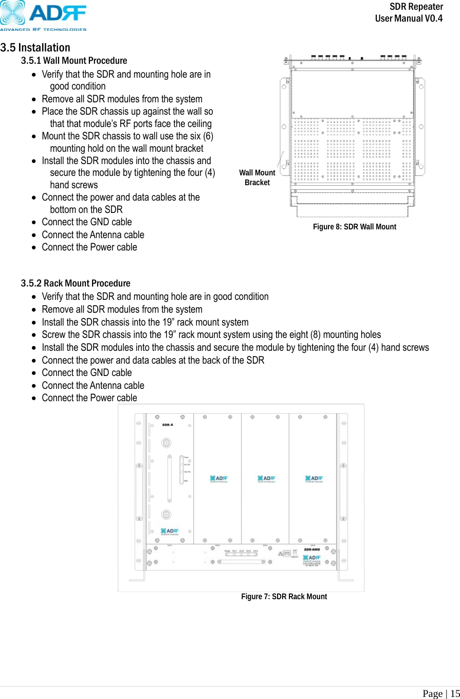
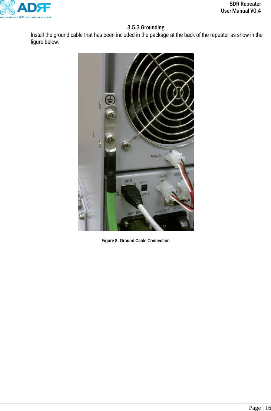
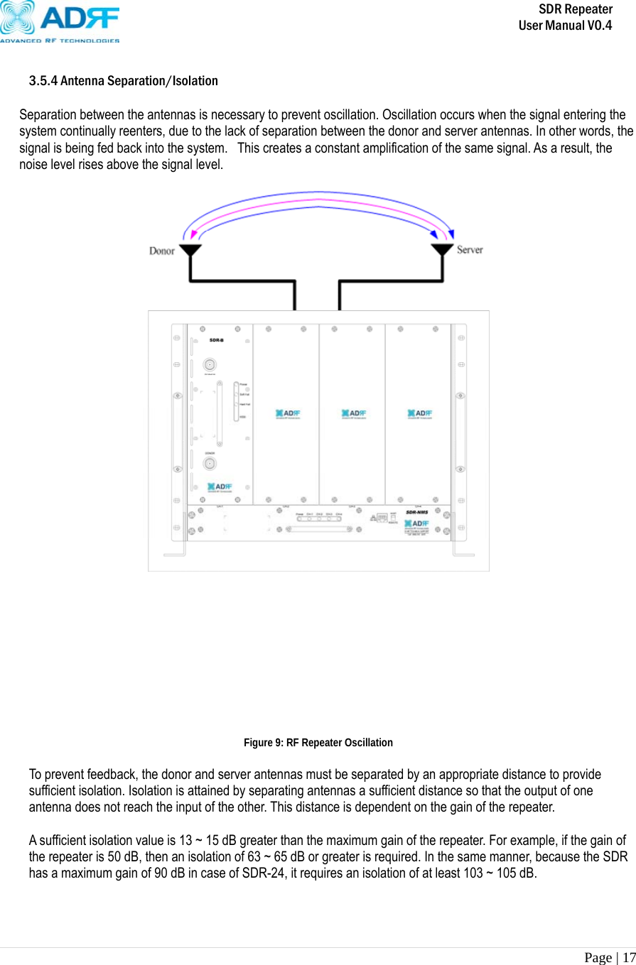
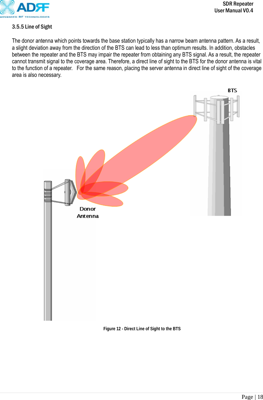
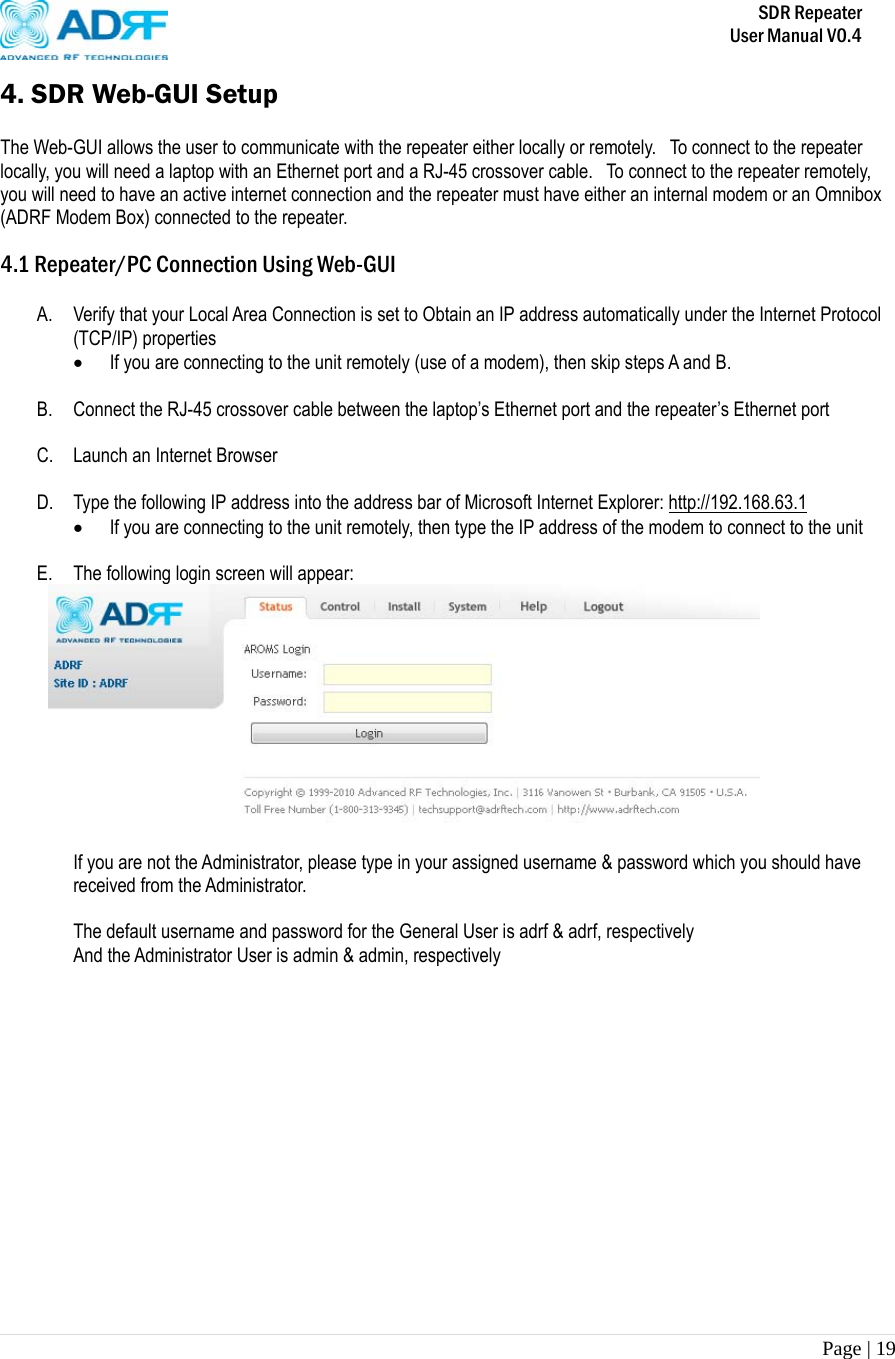
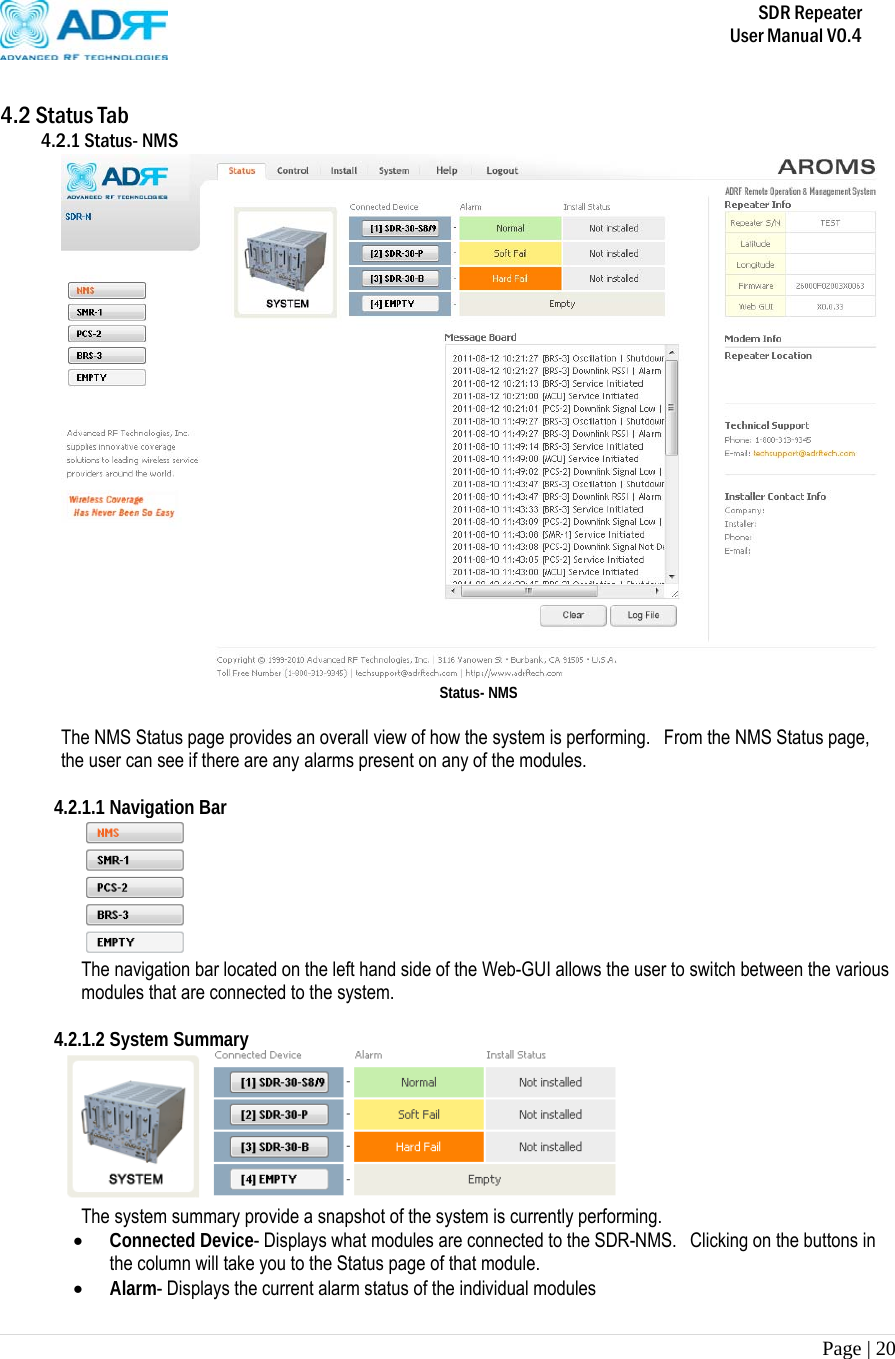
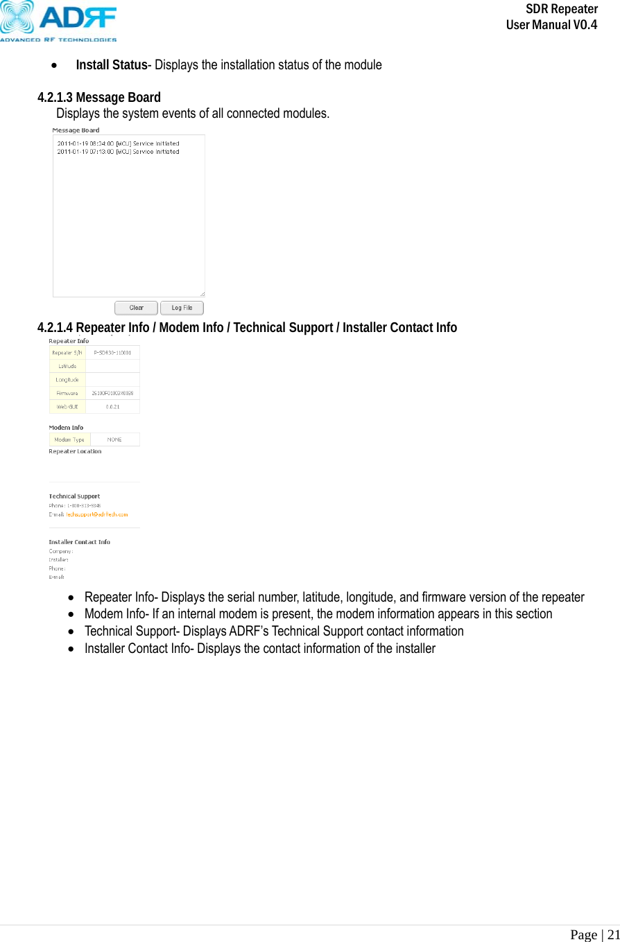
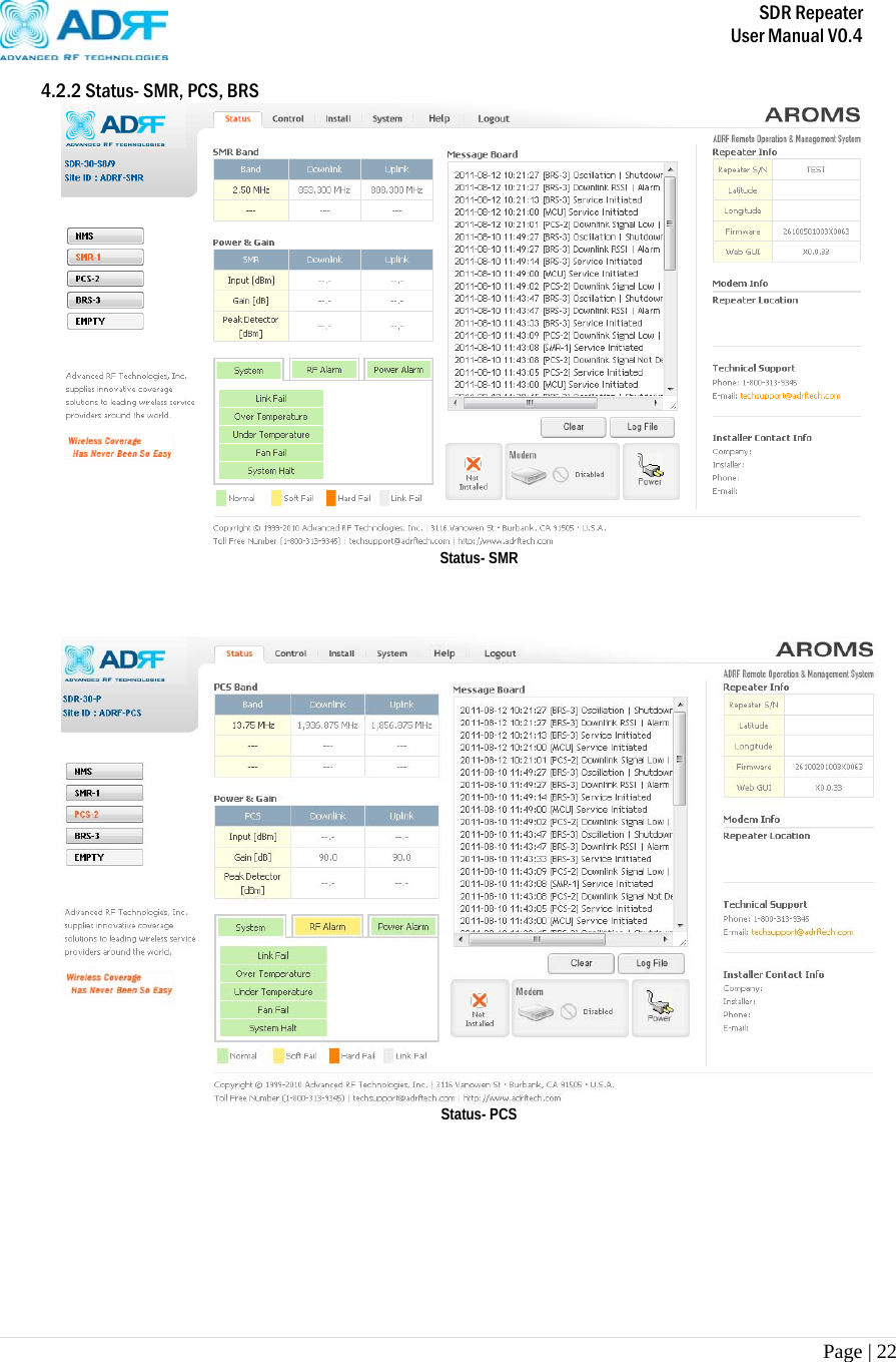
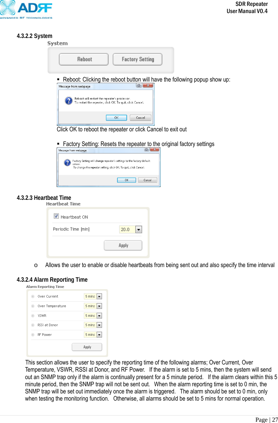
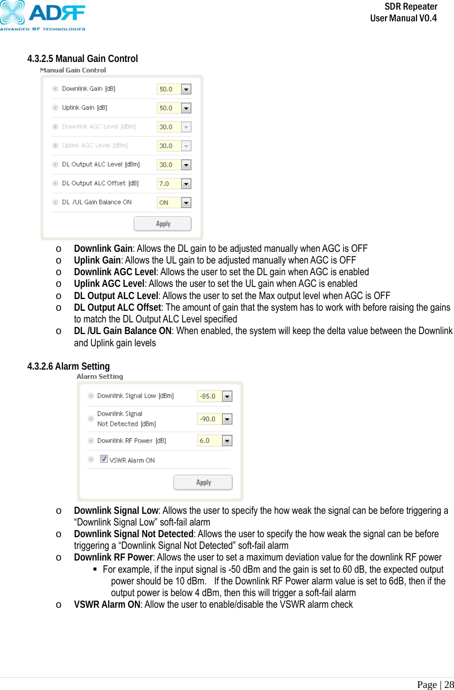
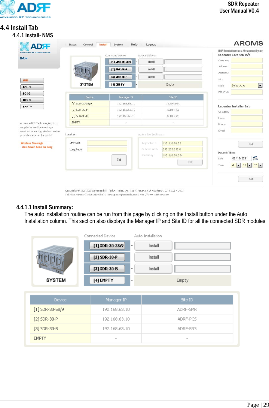
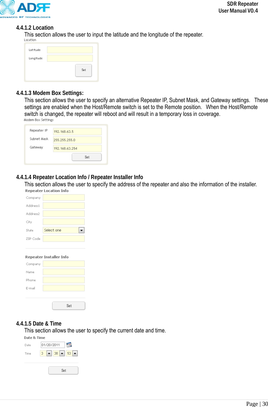
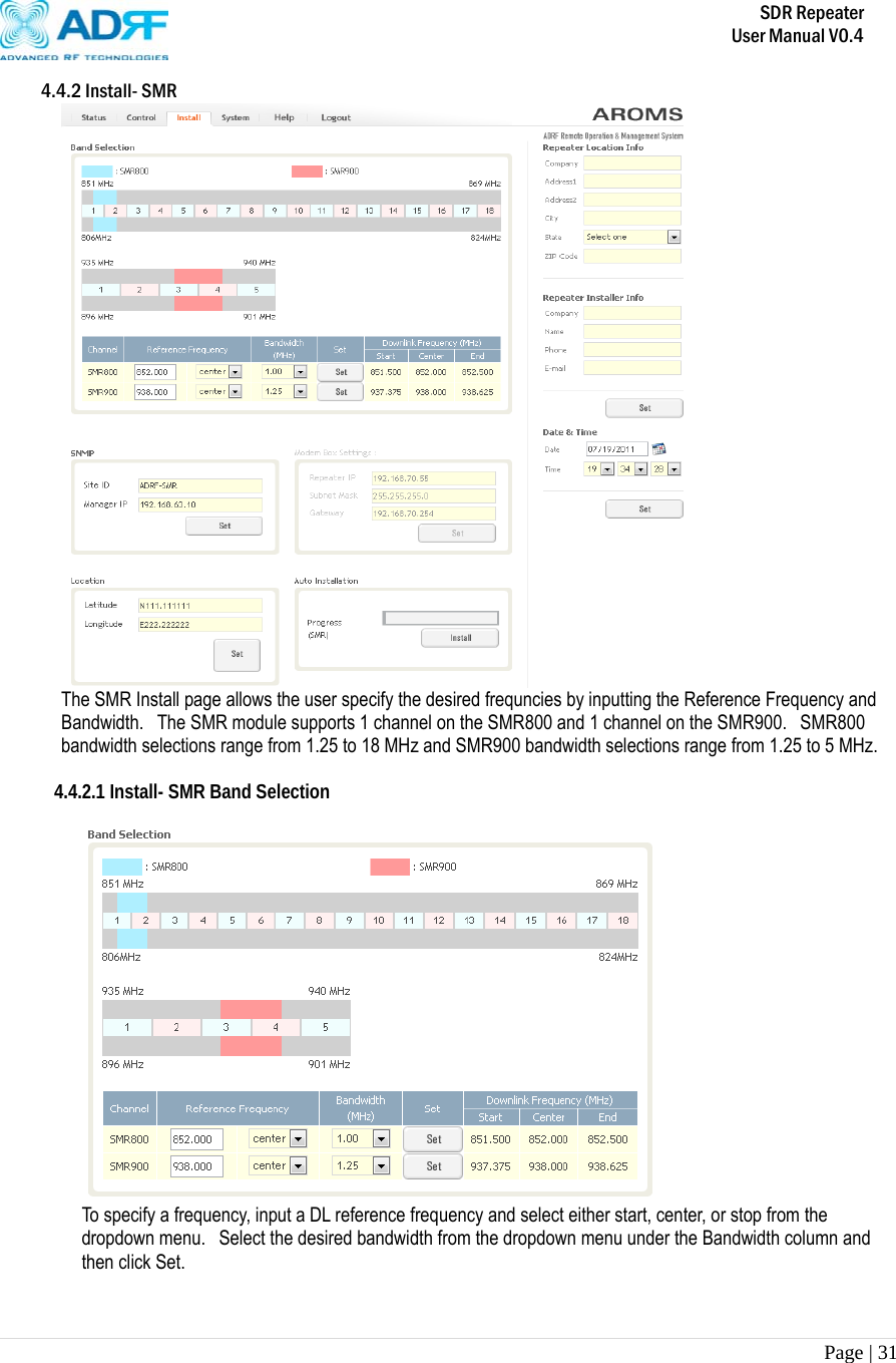
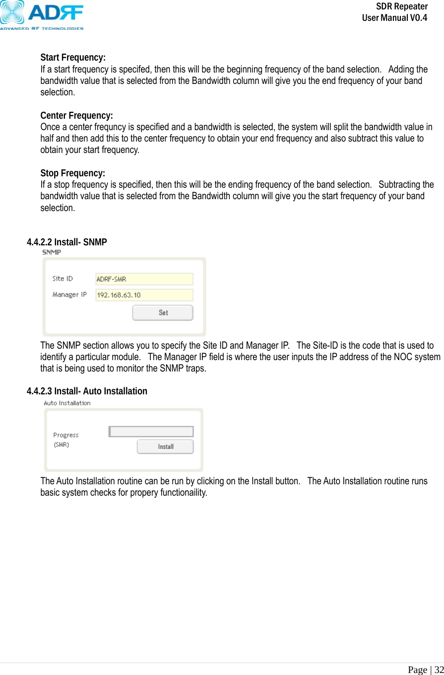
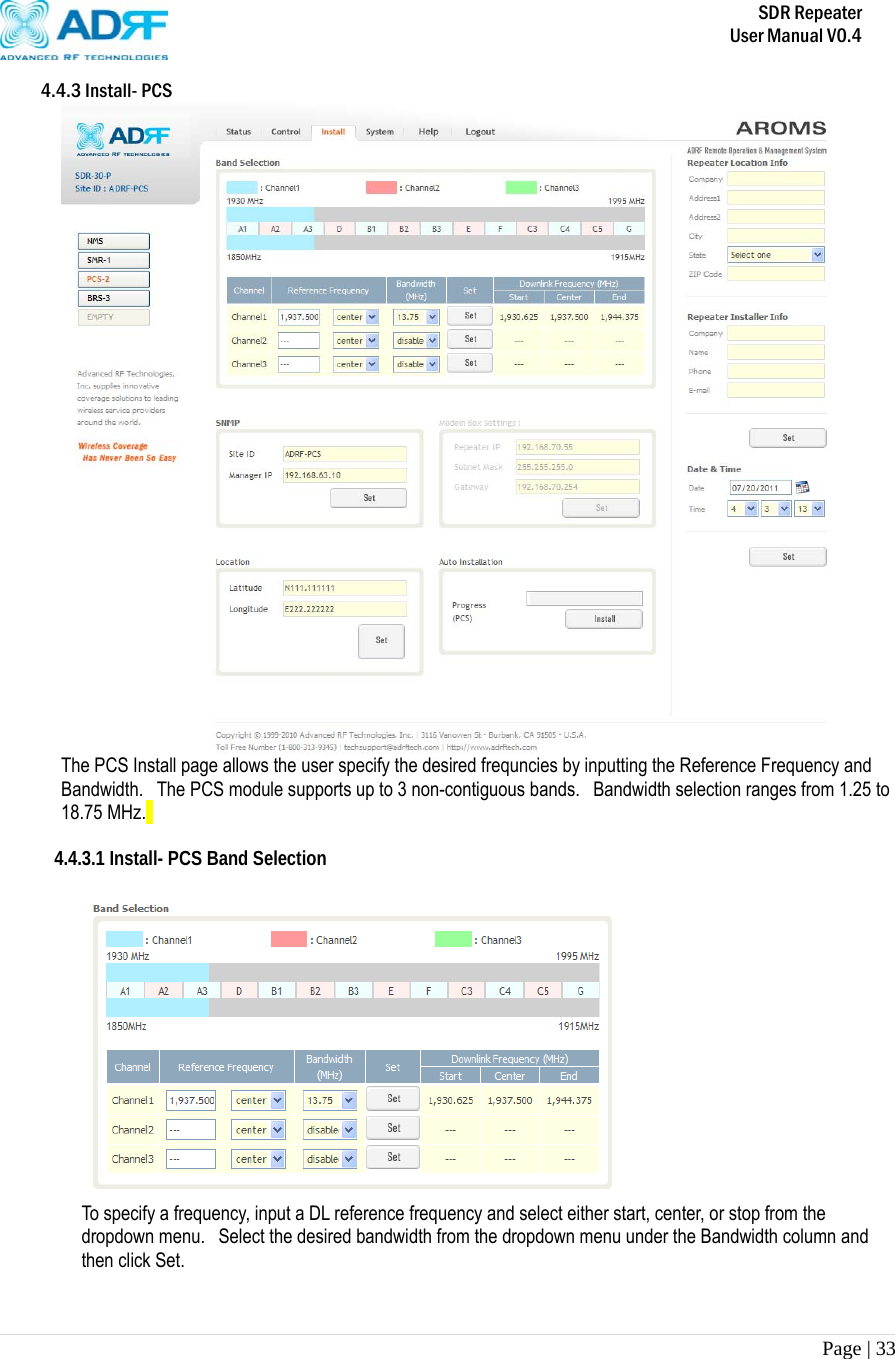
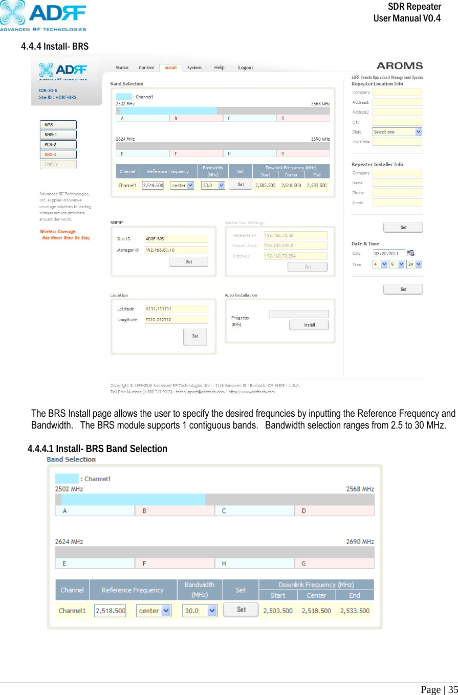
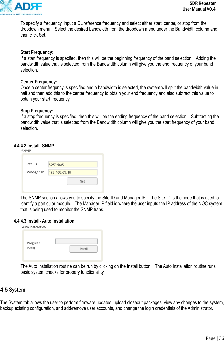
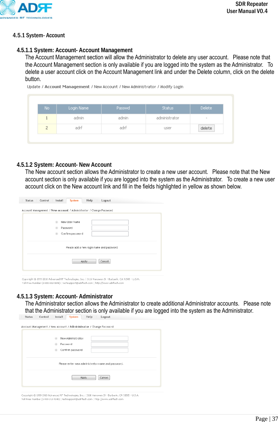
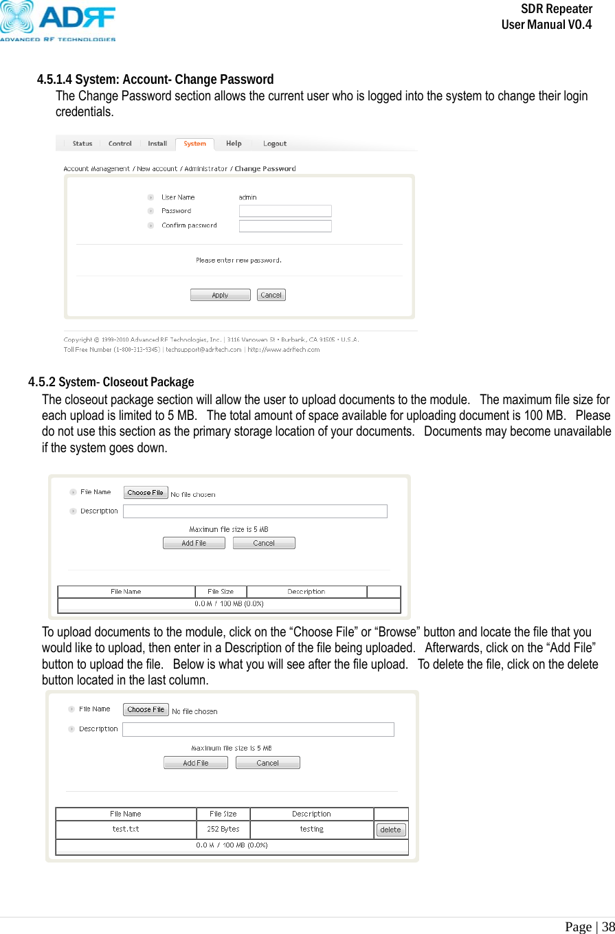
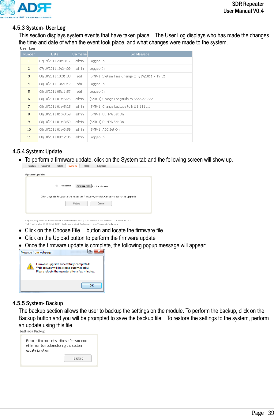
![SDR Repeater User Manual V0.4 Page | 6 1. SDR Repeater 1.1 Introduction Four technologies in one body: SDR is an over-the-air repeater system that can incorporate up to four (4) technologies in one body. Current supported technologies are SMR800, SMR900, PCS, and BRS. 1.1.1 Highlights • Supports up to 4 frequency bands simultaneously o Covers the SMR800, SMR900, PCS, and BRS, LTE, Cellular, AWS bands [SDR-S]SMR800- Covers 18 MHz SMR900- Covers 5 MHz [SDR-P]PCS- Covers 65 MHz 3 independent RF PCS channels, each channel supports 1.25 to 18.75 MHz bandwidth [SDR-B] BRS- Covers 30 MHz [SDR-700]LTE- Covers A+B:12MHz , C:11MHz [SDR-C]Cellular- Covers 25MHz [SDR-A] AWS- Cover 45MHz • Composite Output Power of 24 or 30 dBm • 30 dB AGC Range @ 0.5 dB Step • Adjustable AGC Output Power Level • Adjustable ALC Level • Band Selectable via Web-GUI • Can Support up to 3 Non-Contiguous Bands on the PCS module • Supports Network Management Monitoring System via SNMP • Adjustable FA (3 channels) • Digital filtering • Incremental Automatic Shutdown/Resumption Time: SDR gradually increases the time span between automatic shutdown and resumption before it permanently shuts itself down • Versatility and Usability: SDR gives total control to the user. Most of the control parameters, e.g., gain, output power, alarm threshold, etc. can be changed using the Web-GUI so that the user can adjust the system perfectly to the given RF environment • Web-GUI connectivity via DHCP • Supports DHCP; No 3rd party GUI software required • Automated installation](https://usermanual.wiki/Advanced-RF-Technologies/SDR-B/User-Guide-1643696-Page-6.png)