Advanced Signal SIGPRO Paging Data Receiver User Manual Operational Manual
Advanced Signal Corporation Paging Data Receiver Operational Manual
Operational Manual

Version 1.8.0.4 July, 1999 General Information 1 - 1
FCC ID: NKO-SIGPRO
General Information
Product Warranty Information
Advanced Signal products are warranted to be free from defects in material and workmanship for a period of
ONE (1) YEAR from the date of shipment. Parts will be replaced free of charge for the full warranty period. The
labor to repair products, or replace defective parts, will be covered on a return-to-factory basis only for the full
warranty period. For warranty service or repair, products must be returned to Advanced Signal, paid by
customer. Modifications made to products not manufactured by Advanced Signal are warranted to be free from
defects in material and workmanship for a period of NINETY (90) DAYS from the date of shipment.
Limitation on Damages
THE ABOVE WARRANTIES ARE PURCHASER’S EXCLUSIVE WARRANTIES AND NO OTHER WARRANTY,
EXPRESS OR IMPLIED, SHALL APPLY. ADVANCED SIGNAL SPECIFICALLY DISCLAIMS THE IMPLIED
WARRANTIES OF MERCHANTABILITY AND FITNESS FOR A PARTICULAR PURPOSE. ADVANCED
SIGNAL’S LIABILITY TO PURCHASER FOR ANY CAUSE WHATSOEVER SHALL BE LIMITED TO THE
PURCHASE PRICE PAID TO ADVANCED SIGNAL FOR THE PRODUCTS THAT ARE THE SUBJECT OF
PURCHASER’S CLAIM. IN NO EVENT WILL ADVANCED SIGNAL BE LIABLE FOR ANY DAMAGES
RESULTING FROM LOSS OF DATA OR USE, LOST PROFITS OR ANY INCIDENTAL OR CONSEQUENTIAL
DAMAGES. THESE LIMITATIONS AND DISCLAIMERS ARE NOT MADE BY ADVANCED SIGNAL WHERE
PROHIBITED BY LAW.
Other Disclaimers
Non-Advanced Signal manufactured products and batteries are excluded from this warranty. Non-Advanced
Signal manufactured products are subject to the warranty provided by their manufacturers. Advanced Signal
reserves the right to use reconditioned or refurbished parts. These reconditioned or refurbished parts are
warranted as new.
Computer Software Copyrights
Advanced Signal warrants that its software and firmware designed by Advanced Signal will execute its
programming instructions when properly installed. Advanced Signal does not warrant that the operation of the
instrument, or software, or firmware will be uninterrupted or error free. Advanced Signal products may include
copyrighted Advanced Signal computer programs stored in semiconductor memories or other media. Laws in
the United States and other countries preserve for Advanced Signal certain exclusive rights for copyrighted
computer programs, including the exclusive right to copy or reproduce in any form the copyrighted computer
program. Accordingly, any copyrighted Advanced Signal computer programs contained in the Advanced Signal
products may not be copied or reproduced in any manner without the express written permission of Advanced
Signal. Furthermore, the purchase of Advanced Signal products shall not be deemed to grant either directly or
by implication, estoppel, or otherwise, any license under the copyrights, patents or patent application of
Advanced Signal, except for the normal non-exclusive, royalty free license to use that arises by operation of law
in the sale of a product.
Service Warranty Information
Return Of Equipment
If a product malfunctions or fails in normal use within the Warranty period: (a) the purchaser shall promptly notify
Advanced Signal of the problem and the serial number of the defective product. Advanced Signal shall, at its
option, either resolve the problem over the telephone or issue a Return Authorization Number to the purchaser.
The purchaser shall, at its cost, ship the product to Advanced Signal at the time the Return Authorization
Number is issued;
(b) the return authorization number must be shown on the label attached to each product returned. A
description of the fault must accompany each product returned. The returned product must be properly packed,
and the insurance and shipping charges prepaid;

Version 1.8.0.4 July, 1999 General Information 1 - 2
(c) Advanced Signal shall either repair or replace the returned product. The replacement product may be new
or refurbished; where refurbished, it shall be equivalent to new in operation. When a returned product is
replaced by Advanced Signal, the returned product shall become the property of Advanced Signal;
(d) Advanced Signal shall, at its cost, ship the repaired product or replacement to the purchaser. If the
purchaser has requested Express Shipping, the purchaser shall pay the cost of the shipping; and
(e) Products which are repaired or replaced by Advanced Signal shall be free of defects in material and
workmanship that would prevent compliance in all material respects with the corresponding documentation for
the remainder of the original Warranty or 90 days from the date of repair or replacement, whichever is longer; all
other terms of this Warranty apply to such repairs or replacements.
Caution
Improper use of your SIGNALpro may violate the provisions of the Electronic Communications Privacy Act of
1986 through intentional unauthorized use of protected radio communications. Every effort is made to limit the
sale of SIGNALpro to genuine radio paging operators and law enforcement agencies. Advanced Signal
unequivocally assumes no responsibility for any laws that may be broken, intentionally or otherwise, through the
direct or indirect use of this, or any associated product.
This device complies with part 15 of the FCC rules. Operation is subject to the condition that this device does
not cause harmful interference. Changes or modifications to this equipment not expressly approved by Advanced
Signal are prohibited and may result in loss of the use of the device.
Technical Specifications
System Requirements:
A paging channel receiver and a Windows 3.1X or WIN95 personal computer are required for operation.
Power:
Universal AC: 90 - 132VAC, 175 - 264 VAC, 47-63Hz automatic switching
Internal DC Battery
Front Panel DC Input
Paging Formats:
FLEX 1600 to 6400 bps, 2 and 4 level
ReFLEX25/50
InFLEXion
POCSAG 512/1200/2400
GSC
Guard tones 75/331/750/1500 baud
Analog Input:
1 input per DSP Input ±7.00 V Peak (AC + DC), 200 millivolt minimum signal
Parallel I/O:
10 Out Trig 1
A trigger is produced every 0, 15, 30, and 45 seconds past the minute. When the unit is synchronized to GPS
this trigger can be used to display the start of the 1 second pulse as well as the start of a FLEX frame (provided
that the system frames are sync’d to GPS). This may be used to obtain readings on the relative phasing
between transmitters that cannot otherwise be measured by the control system.
Place one scope probe on the audio signal, a second on the one pulse per second output, and a third on trigger
1. Set the scope’s trigger for channel 3, DC coupled, falling edge, 2.0V, single trigger, no filtering. Arm the
trigger just before the top of the minute. At the top of the minute the scope will trigger displaying the time
difference between the start of the one pulse and the start of the FLEX frame.
Speaker:

Version 1.8.0.4 July, 1999 General Information 1 - 3
Built-in audio monitor speaker, audio selected via the GUI
Physical Dimensions:
8.25”W x 5.0”H x 12.75” D, approximately 13.0 lbs.
Temperature 0 - 50° C with unrestricted ventilation
PC Requirements:
Minimum 486/66 MHz cpu, Windows 3.1x or WIN 95/98, 16MB RAM, 10MB disk space recommended for single
channel decoding
The SIGNALpro software is stored in FLASH memory that can be upgraded by the user through the PC
Graphical User Interface.
Specifications subject to change without notice.
Options & Accessories
The basic configuration of your SIGNALpro contains the SIGNALpro chassis. When ordering a SIGNALpro you
must decide on the following three items.
1) You can select up to four DSP input cards to provide paging channel decoding of up to four channels
simultaneously.
2) In addition, an internal GPS receiver option can be selected to provide precise location information such as
latitude, longitude, time, and satellite status, a 1 pulse per second timing reference, and real-time differential
capability. The GPS option allows you to determine if FLEX is being transmitted at exactly the same time frame
after frame. The GPS receiver option includes a mag mount antenna and antenna cable.
3) You may also select from a variety of AC input cords depending on your specific needs.
Options
The following are wideband internal receivers that ordered for your SIGNALpro. The IF is 15.0 kHz and can be
used for standard 4.8 kHz deviation paging.
SP - 917RX- WB 917-950 MHz
SP - 320RX- WB 322-329 MHz
SP - 280RX- WB 276-286 MHz
SP - 167RX- WB 167-175 MHz
SP - 159RX- WB 159-167 MHz
SP - 151RX- WB 151-159 MHz
SP - 143RX- WB 143-151 MHz
SP - 135RX- WB 135-143 MHz
The following is a narrow band internal receiver that can be ordered for your SIGNALpro. The IF is 7.5 kHz and
can be used for standard 2.4 kHz deviation paging.
SP - 917RX- NB 917-950 MHz
SP - 890RX- NB 890-915 MHz
SP - SQC
A PCB relay allows the SIGNALpro to switch between an internal narrowband receiver and an external scanner.
The SQC software allows the user to measure and display InFLEXion Signal Quality Calibration (SQC)
measurements.
SP - R8500
Used with SP-SQC. An ICOM R8500 scanner is modified to provide AMSSB audio to the SP-SQC.
Version 1.8.0.4 July, 1999 General Information 1 - 4
SP - CASE
A carrying case can be purchased for your SIGNALpro providing an easy method for transporting or carrying
your unit. The case contains two side pockets for the AC input cord, GUI console cable, GPS antenna and
cable, user’s guide, and other miscellaneous items.
SP - HCASE
A hard-side case can be purchased for your SIGNALpro providing a protective environment for shipping, or
transporting the unit to and from different locations.
SP - TCASE
This hard-side shipping case contains a handle and wheels for easier transport. Because of size it must be
checked for airline travel.
SP - DSP2
This option allows you to return your SIGNALpro to the factory to have the unit upgraded to the DSP2 input
card(s).
SP - GPS
This option allows you to return your SIGNALpro to the factory to have an internal GPS receiver installed. This
GPS receiver option includes an active mag mount antenna and antenna cable.
SP - MAINT
Each SIGNALpro is sold with the first year’s software maintenance plan provided. In subsequent years, you may
select this option which provides another year of software maintenance. This option applies to individual
SIGNALpro units.
SP - MAIN - EXT
Each SIGNALpro is sold with the first year’s software maintenance plan provided. This option allows you to
extend the coverage of the software maintenance plan for the functional lifetime of your SIGNALpro. This option
applies to individual SIGNALpro units.
SP - HWMAIN - 5
Each SIGNALpro is sold with a one-year hardware warranty. You may select this option which provides up to five
years hardware warranty coverage. This option applies to individual SIGNALpro units.
SP - HWMAIN - L
Each SIGNALpro is sold with a one-year hardware warranty. You may select this option which provides hardware
warranty coverage for the functional lifetime of the unit. This option applies to individual SIGNALpro units.
RX-MOD
This option can be purchased to have Advanced Signal modify an external receiver to use with your SIGNALpro.
Please consult Advanced Signal prior to purchasing a unit.
SP- NIU
This cable option allows you to connect an external NIU to the Parallel I/O connector of your SIGNALpro. This
provides both 2 and 4 level FSK directly from the transmitter controller when it is not connected to a live
transmitter.
SP- C2K
This cable option allows you to connect a C2000 to the Parallel I/O connector of your SIGNALpro. This provides
both 2 and 4 level FSK directly from the transmitter controller when it is not connected to a live transmitter.
SP- CLOOP
This option is for the Closed Loop System Test program that allows you to generate, and reconcile, test pages or
simulated paging traffic.
SP- MAP
Version 1.8.0.4 July, 1999 General Information 1 - 5
Atlas GIS mapping package allows you to take BER, CWER, and Peak Edge Error Measurements collected
from a SIGNALpro and creates Simulcast Performance Maps. This applies to U.S. customers only.
SP- MAP - STREET
Street maps for specific MSAs or counties in the U.S.
SP- MAP- STATE
Street maps for specific states in the U.S.
SP- MAP - REG
Street maps for specific regions of the U.S.
SP- MAP- NW
Street maps for the entire U.S.
Accessories
• SIGNALpro User’s Guide
• 6’ PC Cable to connect your PC to your SIGNALpro
• One BNC to RCA Phono Jack Connector per DSP input card
• Two Jumpers per DSP input card that can be used with the parallel I/O
• Cigarette lighter adapter
• Cable(s) for connecting the Rx Audio Out to the Slot X Input.
• Antenna(s) for internal receiver(s)
• 4” Jumper Cable for each DSP Input Card
Version 1.7 July, 1999 Hardware 2 - 6
Hardware
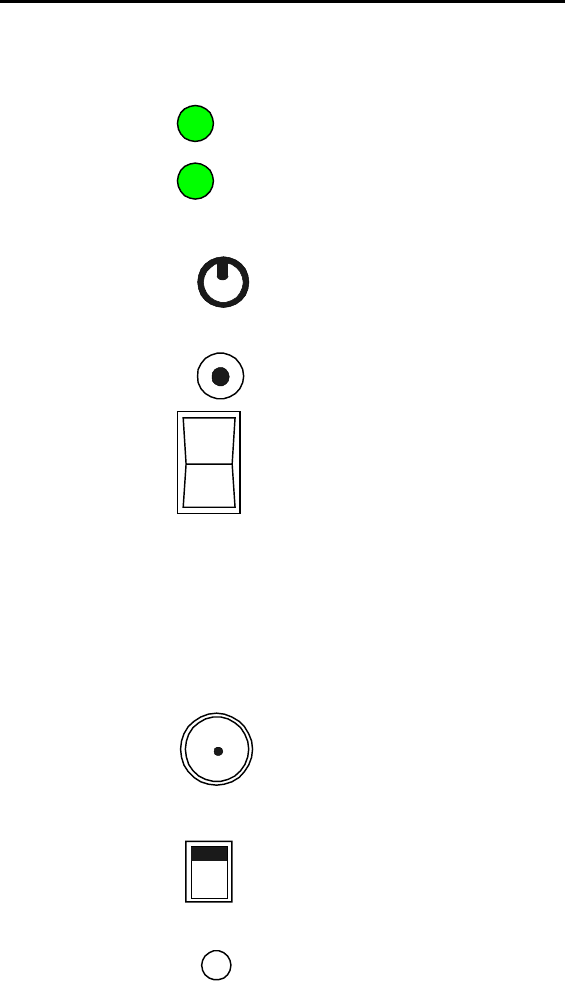
SIGNALpro Front and Rear Panel Features
DC/DC Converter Card
Battery
Charge
Power
Volume
DC
Input
On
Off
(Green = battery is at full charge, Amber = less
than full charge, Red = the battery is near
discharge)
(Green = the unit is operating from any power
source, and not lit when the power switch is off)
(this control knob adjusts the volume level of the
rear speaker output)
(this dc input jack is used to connect a cigarette
lighter adapter with tip positive polarity; 11-15
VDC)
(this switch turns the unit on or off)
NOTE: Battery life can be reduced if the battery is subjected to multiple deep discharge cycles. To
preserve battery life, discontinue use of your SIGNALpro when the battery charge LED is red. If the
battery completely discharges the Power LED will have no color and the Battery Charge LED could be any
color.
OSC_GPS Card
10MHz
In/Out
Local
Ext.
GPS
Ant
10MHz
(this jack accepts a 10 MHz sine wave input when
the 10 MHz switch is ext, or provides an output
when the 10 MHz switch is Local)
(this slide switch allows you to select between
using an internal or external 10 MHz reference, the
unit will not operate properly if this switch is set for
external and no 10 MHz is provided)
(this jack provides a connection for the GPS
receiver antenna provided with the internal GPS
option)

Version 1.7 July, 1999 Hardware 2 - 7
Host CPU Card
Status
OSC Lock
Spare
Outputs
1PPS
Console
GUI
(LED indications provided below)
(LED indications provided below)
(These outputs are currently inactive.)
(This output provides a 1pps reference that can
used as a time reference. In GPS mode this 1pps
within 500 nsec of the GPS 1pps.)
(This DB9 connector provides the connection
your personal computer running the GUI, use the
cable provided with your unit.)
34
12
Status LED
Slow Flashing Green
If the GPS RX is present and in use, this indicates that the GPS receiver is tracking 4 or more
GPS satellites. If GPS is not in use, it indicates the unit is ready for use.
Slow Flashing Amber
The GPS RX is present, in use, and currently tracking two or three GPS satellites.
Fast Flashing Amber
The GPS RX is present but it is either not responding or is currently tracking only one GPS
satellite.
Fast Flashing Red
GPS self test failed
OSC LED
Solid Green
OSC is currently locked and aligned with GPS one pulse per second.
Slow Flashing Amber
OSC is in the process of aligning and locking to the GPS one pulse per second
Fast Flashing Amber
OSC is rapidly changing in order to align and lock to the GPS one pulse per second. All DSP
decoding is disabled during this time.
Slow Flashing Red
OSC is rapidly changing to align with the GPS 1PPS
When the Status and OSC LEDs are both fast flashing red, your SIGNALpro is running from internal
ROM. If you encounter this situation contact Advanced Signal for assistance.

Version 1.7 July, 1999 Hardware 2 - 8
DSP Input Card
Rx Ant
Fmt
Rate
Rx
Audio
Out
Slot X
Input
4
Level
Out
Parallel
I/O
BER
Sync
This is an external antenna connection for the internal receiver.
LED definitions are provided below.
This RCA jack is the audio output from the internal RX. This output
should be connected to the SLOT X input below. Use the jumper
provided.
This RCA jack is an audio input. You may an internal RX or external
RX.
This RCA jack is an audio output. It is a reconstructed audio signal
from the MSB/LSB connections made to the parallel I/O. Use the
jumper provided to connect this output with the SLOT X audio input.
Currently available outputs are listed below.
Format:
Green = POCSAG, Amber = FLEX, Red = Golay, off during guard tone decoding
Rate:
Green = 512/1600/Golay, Amber = 1200/3200, Red = 2400/6400. This LED will also illuminate if guard
tone is detected. Green = 75/331/750, Amber = 1500.
BER:
Amber = 1 or 2 bit errors detected in a codeword, Red = Codewords received with unrecoverable errors,
off = no errors detected.
Sync:
Green = sync received and decoded, FLEX sync error < 500 usec, Amber = error > 500 usec, Red = error
> 1.5 msec.
LED Examples:
1. Format Amber
Rate Amber
BER OFF
SYNC Green
This indicates FLEX 3200 bps was received in-sync with previous FLEX transmissions, and no bit errors.
2. Format Green
Rate Red
BER Amber
SYNC Green
This indicates POCSAG 2400 bps was received with correctable bit errors.
Version 1.7 July, 1999 Hardware 2 - 9
NOTE: If you are operating in the RSSI only mode the Fmt LED will be Green and the Sync LED will
Flash Green one second on, one second off.
Parallel I/O Outputs:
10 Output Trig 1 See page 1-2
9 Output Trig 2 See page 1-3
8GND
7 Input Invert Audio active low ground this input using the 2 position jumper to pin 7
& 8 if the audio from the receiver needs to be inverted.
6 Output +5VDC - current limited by 25 ohms of resistance
5 Output +5VDC - current limited by 25 ohms of resistance
4 Input Symbol LSB
3 Input Symbol MSB
2GND
1GND
Note: The DSP Input Card will fail to achieve Sync if the audio provided represents inverted data.
The following information provides detailed connections between the DSP2 and various control
equipment. Please note that there is not a connection method identified for the Motorola products using
the internal NIU.
DSP2 Parallel I/O Pin out:
Pin 1 Ground
Pin 3 Symbol MSB
Pin 4 Symbol LSB
External NIU w/Generic I/O
TB4-2 RXFQ1 (LSB)
TB4-3 RXFQ2 (MSB)
C2000 Exciter Connector
J4-3 TDA+ (MSB)
J4-34 TDB+ (LSB)
J4-10 Ground
External NIU w/Generic I/O:
TB4-2 RXFQ1 (LSB)
TB4-3 RXFQ2 (MSB)
Data connections for Glenayre equipment can be made at the exciter I/O board independent of control
equipment type as follows:
Universal Exciter:
Access to the data inputs are available at screw terminals on the I/O board, D1 (LSB) and D2. (MSB)
DSP Exciter:
Connections to the DSP Exciter vary depending on the type of interface board installed in the exciter.
Refer to your equipment documentation to determine the configuration of the equipment to be interfaced.
QT-1000 Interface:
Data LSB - J1-7
Data MSB - J2-1
Standard Interface:
Version 1.7 July, 1999 Hardware 2 - 10
Data LSB - J4-17
Data MSB - J4-5
C2000 Interface:
Data LSB - J2-5
Data MSB - J2-7
INSTALLATION VERIFICATION
The C2000 transmitter controller provides a test feature that may be used to verify installation. The
controller can be taken off-line and placed in the test mode to generate a periodic test pattern. This will
produce an ascending staircase on the data output of the 4 level converter.
The NIU provides a test pattern using the "test txd" command and a data byte of 0x1e to produce an
ascending staircase pattern. Refer to the appropriate equipment manual to utilize these test features.
After connecting the transmitter controller to the parallel I/O you must place the audio connector on the 4
Level Out and Slot X Input connections.
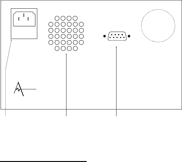
Rear Panel:
AC Input
90 - 132 VAC
175 - 264 VAC
47 - 63 Hz
120 VA max
fuse = 2A
A
SCII serial
p
or
t
DVANCED
SIGNAL
MADE IN U.S.A. WARNING! No o
p
erator serviceable
Parts inside
,
refer service to
service trained
p
ersonnel.
This is for connecting
your AC input power
cord.
This connection provides an
ASCII interface to a "dumb"
terminal. Currently not used.
Speaker
Fan
Receiver Information
Receiver Requirements
The receiver(s) must provide DC coupled, demodulated audio to the DSP input card(s) of your
SIGNALpro. The maximum peak audio input level is ± 7.00V (AC plus DC). The AC (or signal) portion
of the audio should be greater than 200 millivolts peak-to-peak. The audio signal must be DC coupled
from the receiver for reliable data decoding.
Receiver Configurations
The following list of receivers is approved for use with your SIGNALpro. We strongly recommend that you
use a modified pager for field applications and a non-pager receiver for in-house testing. Some receivers

Version 1.7 July, 1999 Hardware 2 - 11
require slight modifications in order to perform properly with your SIGNALpro. If you have a receiver that
is not listed below, please contact Advanced Signal’s Customer Support for guidance.
Internal Receivers
SP-917RX-WB 917-950 MHz, 15 kHz IF, 4.8 kHz deviation
SP-917RX-NB 917-950 MHz, 7.5 kHz IF, 2.4 kHz deviation
SP-890RX-NB 890-915 MHz, 7.5 kHz IF, 2.4 kHz deviation
SP-320RX-WB 322-329 MHz, 15 kHz IF, 4.8 kHz deviation
SP-280RX-WB 274-286 MHz, 15 kHz IF, 4.8 kHz deviation
SP-167RX-WB 167-175 MHz, 15 kHz IF, 4.8 kHz deviation
SP-159RX-WB 159-167 MHz, 15 kHz IF, 4.8 kHz deviation
SP-151RX-WB 151-159 MHz, 15 kHz IF, 4.8 kHz deviation
SP-143RX-WB 143-151 MHz, 15 kHz IF, 4.8 kHz deviation
SP-135RX-WB 135-143 MHz, 15 kHz IF, 4.8 kHz deviation
If you want to use the internal receiver’s audio you must use the short cable supplied with your unit that
connects the RX Audio Out to the Slot X Input. If the cable is not connected the internal receiver will still
provide RSSI information to the console program. If you use the 900 MHz internal receivers a jumper
is required on pins 7 & 8 on the Parallel I/O of your DSP input card(s) to compensate for inverted
audio. Other internal receivers do not require this inversion.
Motorola, NEC, and other Pagers (consult factory for applicable models).
Radio Shack Pro-60 or equivalent (handheld scanner)
The modifications required should be made by Advanced Signal in order to ensure proper operation with
your SIGNALpro. A jumper is required on pins 7 & 8 on the Parallel I/O of your DSP input card(s) to
compensate for inverted audio if you are monitoring VHF or 450 MHz paging frequencies. For best results
use this scanner while operating off batteries. The AC supply causes the BER and CWER readings to be
skewed.
Realistic Pro-2037 & 2042 or equivalent (desktop scanners)
The modifications required should be made by Advanced Signal in order to ensure proper operation with
your SIGNALpro. A jumper is required on pins 7 & 8 on the Parallel I/O of your DSP input card(s) to
compensate for inverted audio if you are monitoring VHF or 450 MHz paging frequencies.
NOTE: All scanner modifications route the audio output to the ear phone jack. The audio cable
provided with the modification should be placed in this jack. The other end (RCA phono
connector) is placed in the Slot X Input on the DSP Input Card.
Motorola External NIU
The TXDATA and GND can be used to provide 2-level data to the SIGNALpro. When used with the SP-
4L-INT or SP-4L-NIU the NIU can provide a direct four-level interface to the SIGNALpro.
Glenayre Universal Exciter
This can be used to provide 2-level data only to the SIGNALpro. Please contact Advanced Signal for
more information. When used with the SP-4L-INT the Glenayre Universal Exciter can provide a direct
four-level interface to the SIGNALpro.
Glenayre DSP Exciter
This can be used to provide 2-level data only to the SIGNALpro. Please contact Advanced Signal for
more information. When used with the SP-4L-INT the Glenayre DSP Exciter can provide a direct four-
level interface to the SIGNALpro. Please contact Advanced Signal for further information.
Glenayre C2000
When used with the DSP2 Input Card, SP-4L-INT or SP-4L-C2000 the C2000 can provide a direct four-
level interface to the SIGNALpro. Please contact Advanced Signal for further information.
RS232

Version 1.7 July, 1999 Hardware 2 - 12
This can be used to provide 2-level data only to the SIGNALpro. Please contact Advanced Signal for
more information.
Receiver Performance Characteristics
The bit error rate calculated by a DSP Input Card in your SIGNALpro will approximate the bit error rate
that a pager would experience while listening to the same RF channel. Advanced Signal does not make
any claims that the performance of a receiver connected to your SIGNALpro DSP Input Card is equal to
the performance of a pager. Pagers are able to limit their decoding task to a specific rate and format.
Your SIGNALpro must be ready to switch to any other format quickly so it does not miss data contained
within the new transmission. This forces your SIGNALpro to use rather stringent rules when deciding to
cease decoding the current format.
You should experiment with the placement of your modified pager or handheld scanner. At 900 MHz, a
few inches may mean the difference between a local null and sufficient signal for the DSP Input Card to
decode. The speaker on your SIGNALpro can be set to listen to a specific slot. Using a modified pager,
and this setting, for the specific slot will allow you to hear the channel even if your SIGNALpro has ceased
decoding. Listen for areas of weak signal as you move the unit around. Field use has shown that
handheld receivers are susceptible to high bit error rates while moving, or when there are bodies in motion
in close proximity to the receiver. If your SIGNALpro is in an area of high RF levels (greater than –
40dBm) you may need to place an attenuator on the RX Input connector.
If you are conducting any type of testing other than simple capcode/message collection we strongly urge
that you use an internal receiver, or a direct connection between the transmitter controller and your
SIGNALpro instead of a modified scanner. These devices have very wide front ends and are quite
susceptible to noise.
GPS Receiver
General Information:
The GPS receiver option includes an 8-channel receiver module and an active mag mount antenna
module. An 18 ft. cable is provided to connect the receiver inside your SIGNALpro to the Antenna.
Acquisition Time (Time To
First Fix) It takes approximately 2 minutes for two satellites to be acquired with a
good view and relatively clear sky. Another two minutes are required
for the oscillator to pull within 50 microseconds of the GPS 1PPS.
During this time the OSC LED is Fast Flashing Amber. Finally, an
additional five to ten minutes is needed for the oscillator to pull within
500 nanoseconds of the GPS 1PPS. During this time the OSC LED is
Slow Flashing Amber. When locked and aligned the OSC LED is Solid
Green.
Positioning Accuracy Less than 25 meters, SEP (without SA) [DoD] may invoke Selective
Availability (SA), potentially degrading accuracy to 100 m
Timing Accuracy (1PPS) 130 nanosec. Observed (1σ) with SA on
During certain periods of the day there may be limited GPS satellites accessible that could prohibit you
from being able to obtain accurate positioning readings.
Operating Information:
The following information applies if you have the internal GPS Receiver option installed in your SIGNALpro
and choose to activate it. At power-up, the Host CPU programs each DSP input card and attempts to
communicate with the internal GPS receiver.
If the GPS receiver is detected the unit will wait for the GPS receiver to acquire at least two satellites.
While in the wait mode the Status LED will fast flash amber. Once the GPS receiver acquires at least two
satellites the unit halts all DSP activity and begins to acquire GPS time and GPS 1PPS from the receiver.

Version 1.7 July, 1999 Hardware 2 - 13
Once GPS time is acquired the unit shifts its time base ± the Greenwich Mean Time (GMT) correction
factor (see page 3-10 for additional information) and begins to lock the oscillator to the GPS 1PPS. The
DSP card(s) continue to hold until the SIGNALpro 1PPS is within 50 microseconds of the GPS 1PPS. The
OSC Lock LED will be slow Flash Red and Fast Flash Amber during this time shift and locking period.
When your SIGNALpro is within the 50 microsecond window it programs the new time and allows the DSP
card(s) to begin operating with the new time and the GPS 1PPS. SIGNALpro will continue to pull its
oscillator until it is within 500 nanoseconds of the GPS 1PPS. The OSC Lock LED should be a Slow
Flashing Amber. Once the 500 nanosecond threshold is met the OSC Lock LED will turn green.
The time associated with received data on all displays will now be the GPS time ± the GMT correction.
Once four or more satellites are acquired the Status LED will turn flashing green.
It takes approximately 2 minutes for two satellites to be acquired with a good view and relatively clear sky.
Another two minutes are required for the oscillator to pull within 50 microseconds of the GPS 1PPS.
Finally, an additional five to ten minutes is needed for the oscillator to pull within 500 nanoseconds of the
GPS 1PPS.
Special Note: It may take fifteen minutes or more for the GPS receiver to acquire an almanac. Longer
acquisition times may also take place if the unit is moved a significant distance from its last known
position. If you wish to discontinue using the GPS option and continue to use your SIGNALpro for
“absolute sync” measurements, you should wait to make sure the OSC LED is green before disconnecting
the GPS antenna. This will ensure continuity between measurements made using the GPS receiver and
measurements made while disconnected. If the OSC LED is not green the internal 10 MHz oscillator is
not locked and aligned with the GPS 1PPS. If you are only interested in relative measurements this will
not matter.
Power Connections
Installing SIGNALpro is very simple; connect it to an AC or external DC power source and turn it on.
Power requirements are labeled on the unit’s rear panel. SIGNALpro does not require you to change any
external voltage settings for AC operation.
For AC power: connect the power cord that came with your SIGNALpro to the rear panel AC input
connection. Plug the other end of the power cord into a receptacle supplying AC power within the range
printed on the unit’s rear panel.
While the unit is operating from AC power the internal battery will charge. Once fully charged, the internal
battery provides DC battery power for approximately 2 hours of operation for one DSP input card, 1 hour
for two DSP input cards, and less than 1 hour for three or four DSP input cards. Please consider an
external battery pack for extended battery use.
The front panel DC input can be used with the car cigarette lighter adapter that was provided with your
unit. Using this source will not charge the internal battery.
Case Handle
The case handle is inserted into the side groove of the case in a position that provides optimum clearance
while carrying the unit. The handle is locking at 90° above or below the case, and the carrying position
has a slight detent only. The handle does not lock in the carrying position.