Advanced Sterilization 100NXRFID Low temperature sterilizer with RFID User Manual RFIDmodule
Advanced Sterilization Products Low temperature sterilizer with RFID RFIDmodule
Contents
- 1. Sterilization system user guide
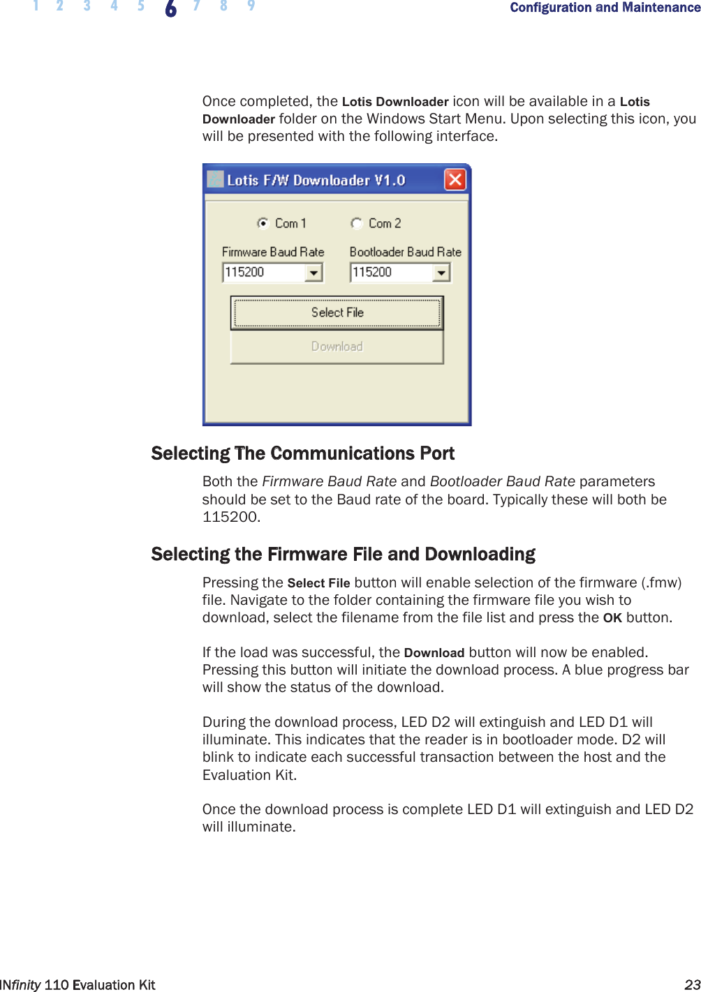
- 2. RFID module user guide
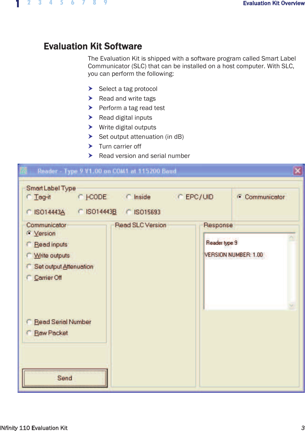
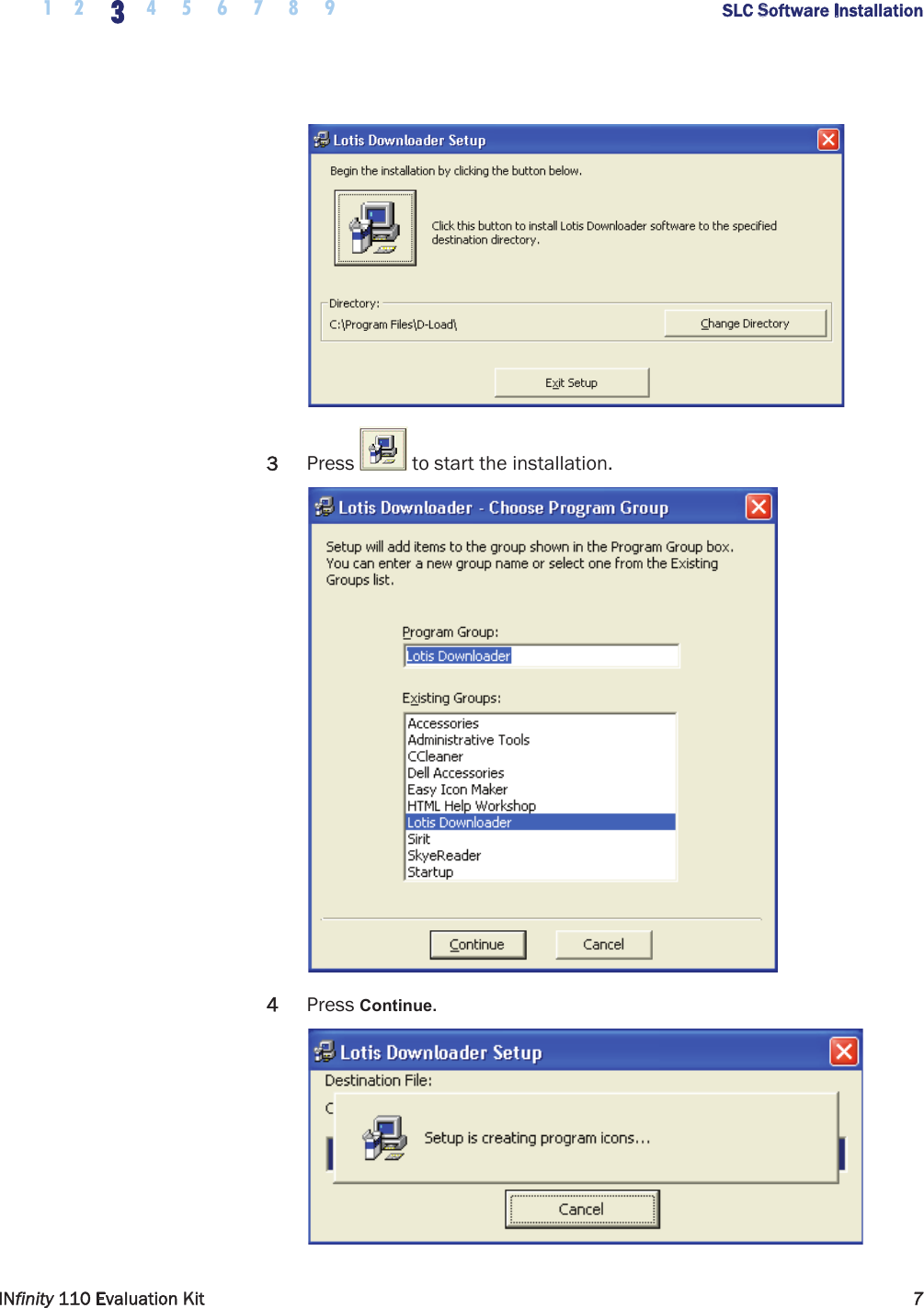
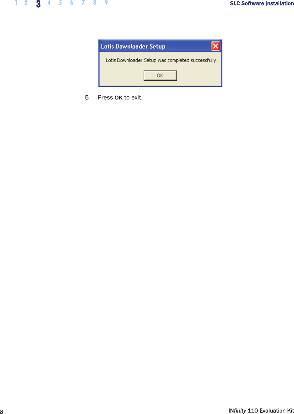
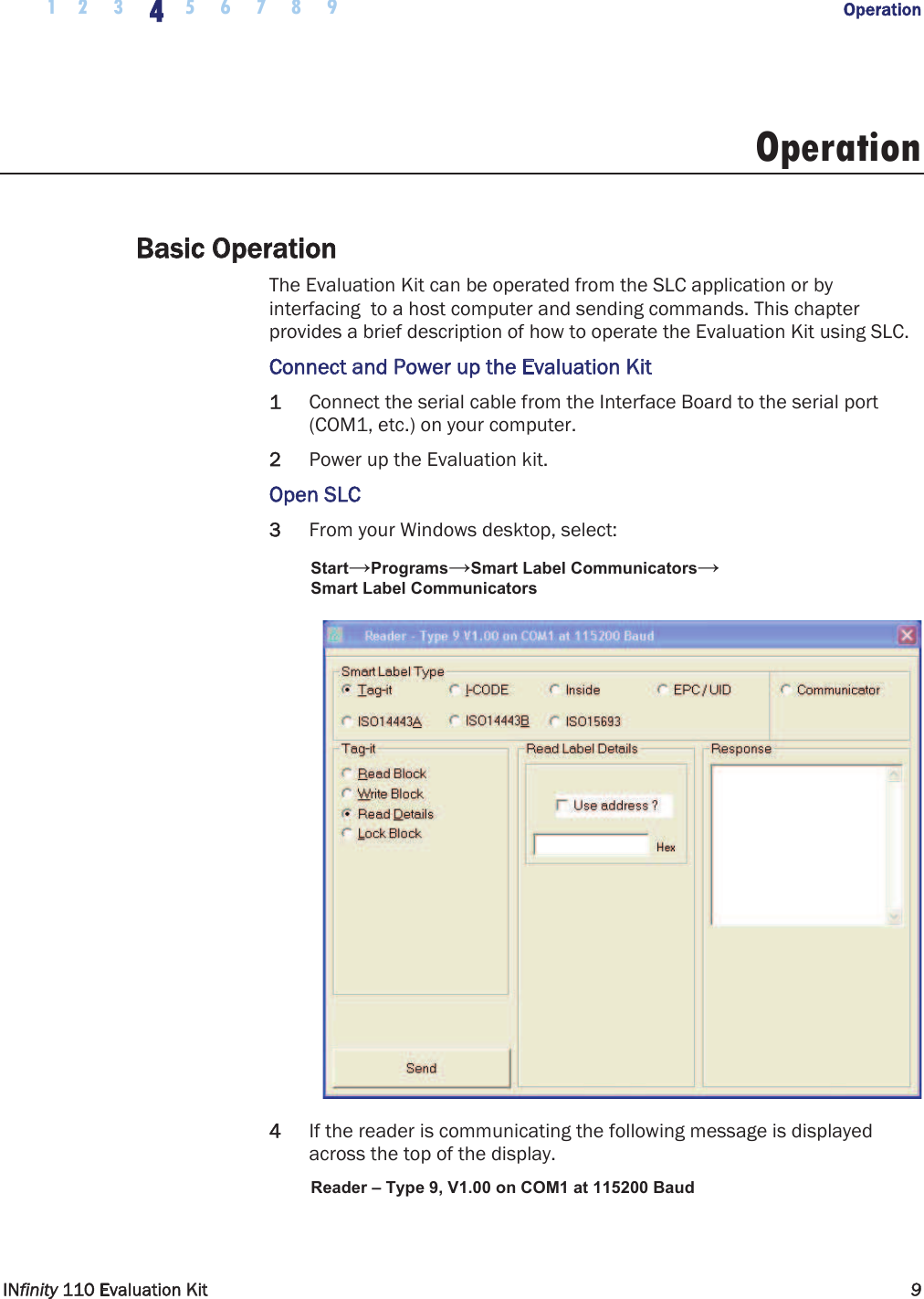
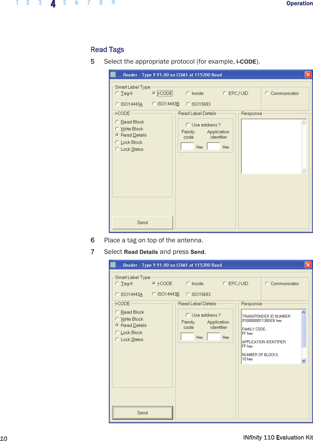
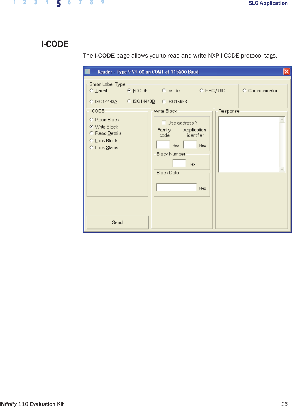
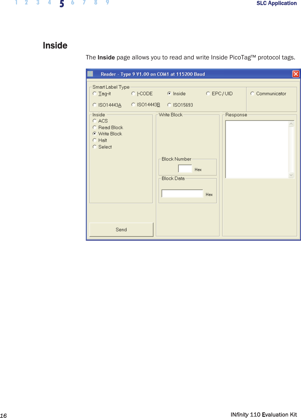
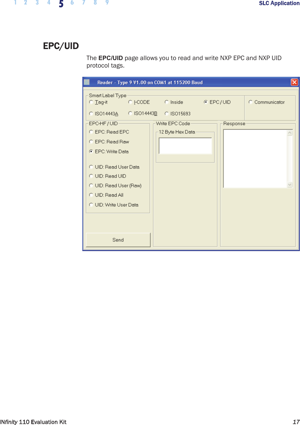
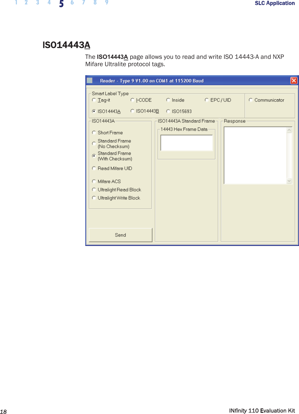
RFID module user guide