Advantech Co ADAM-2051Z Wireless Sensor Network 8-ch Digital Input Node User Manual V4 12 EA User Manual
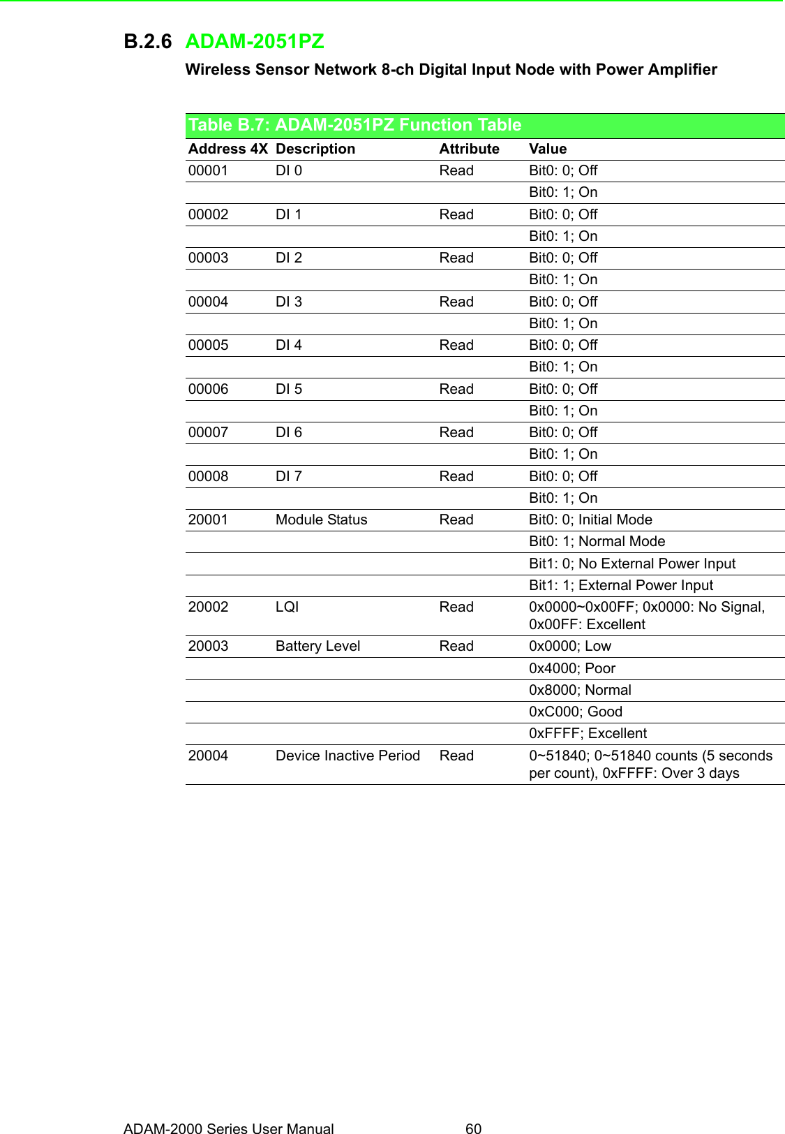
Advantech Co Ltd Wireless Sensor Network 8-ch Digital Input Node V4 12 EA User Manual
UserManual.wiki
>
Advantech Co
>
ADAM 2051Z User Manual
Exhibit 08 Users Manual
Navigation menu
Upload a User Manual
Namespaces
Wiki Guide
HTML
PDF
Info
Views
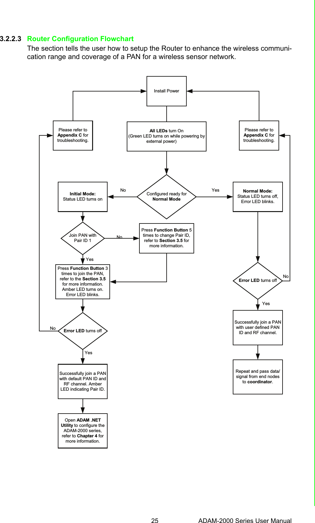
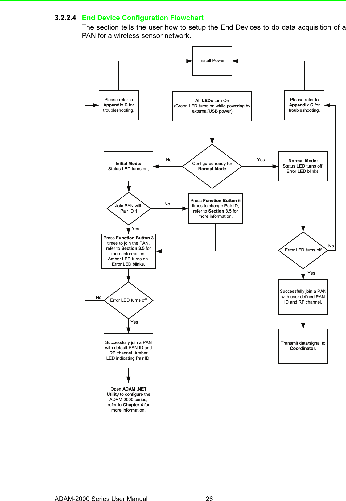
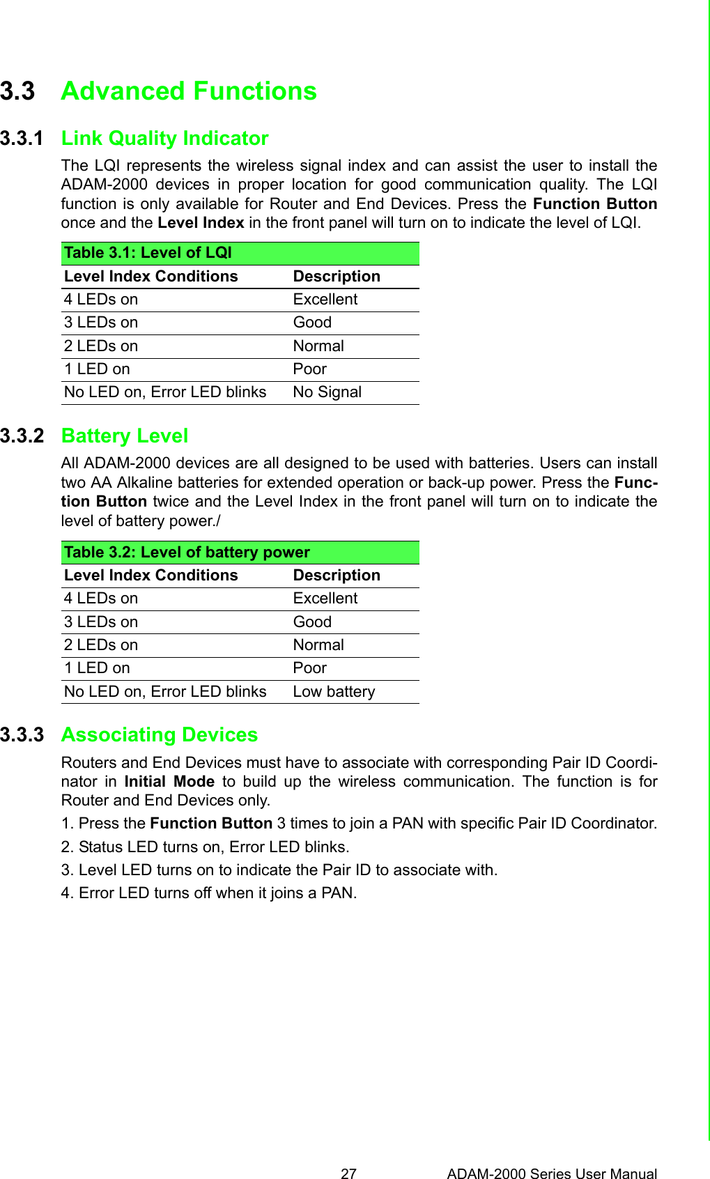
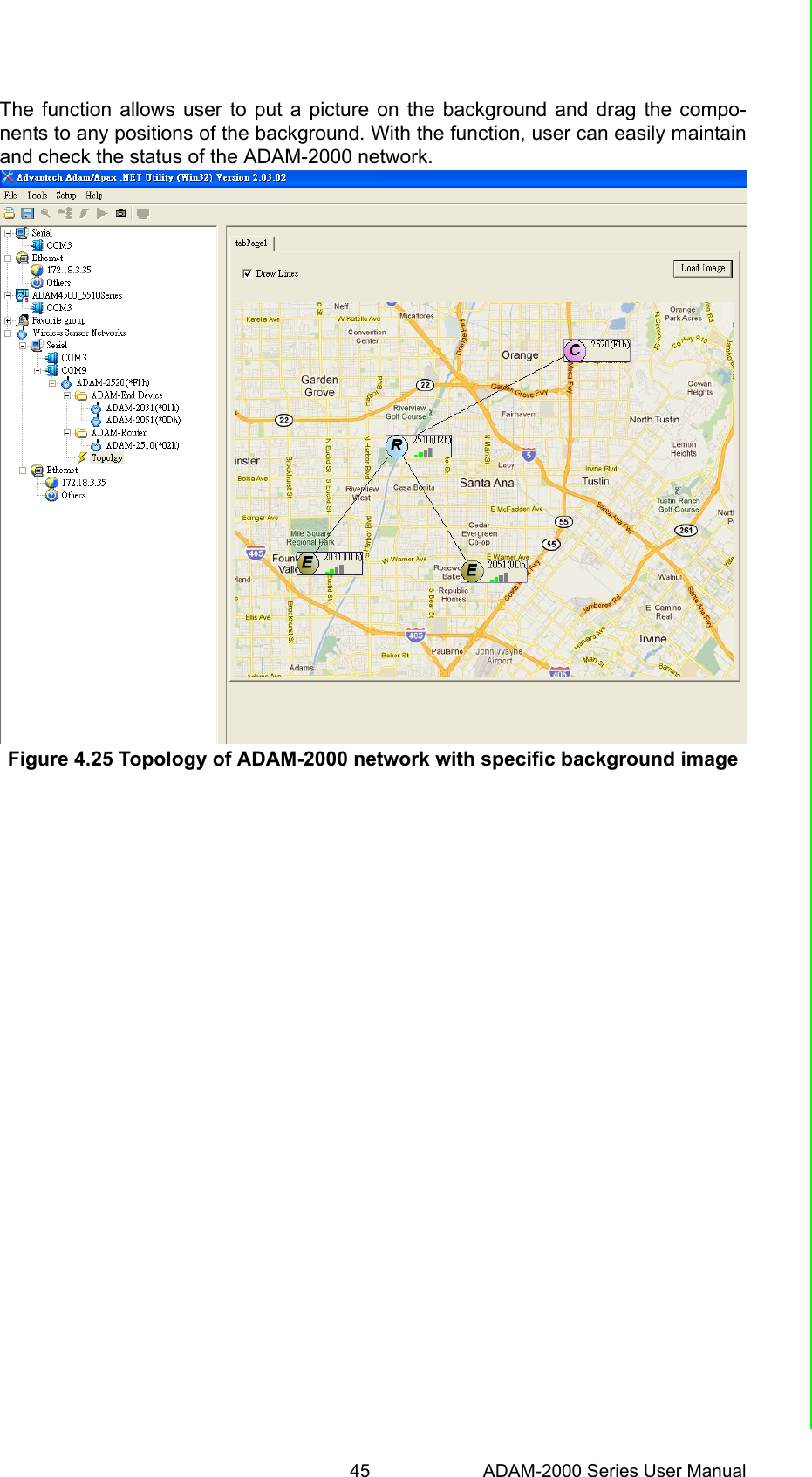
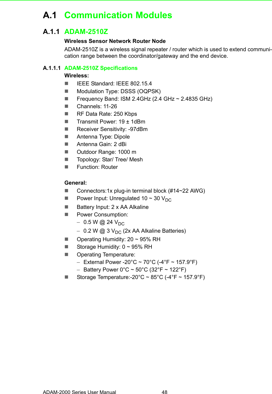
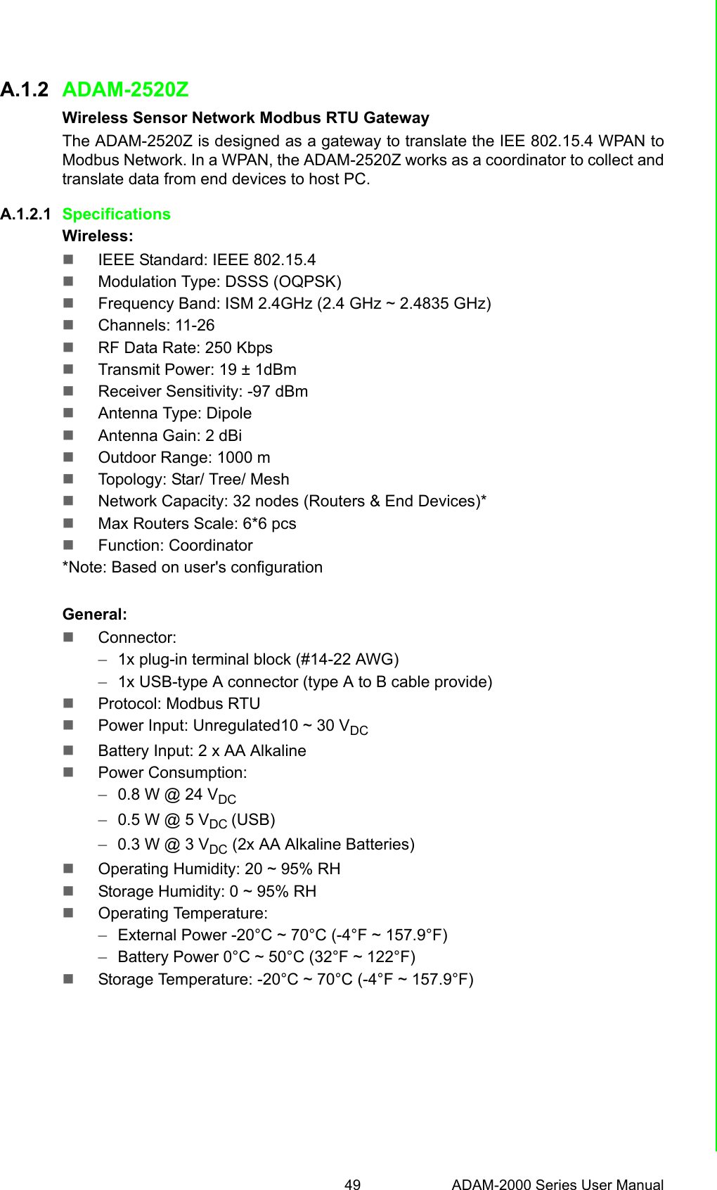
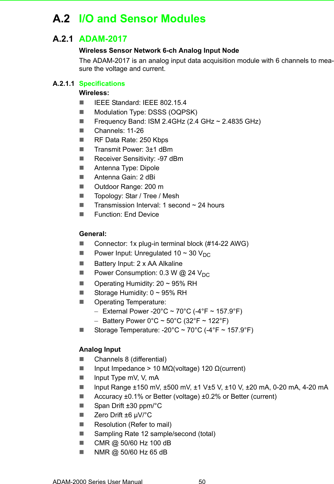
User Manual
Discussion / Help
Navigation