Advantech Co ADAM-6050W 18-Channel Digital I/O Module User Manual ADAM 6050W
Advantech Co Ltd 18-Channel Digital I/O Module ADAM 6050W
User Manual
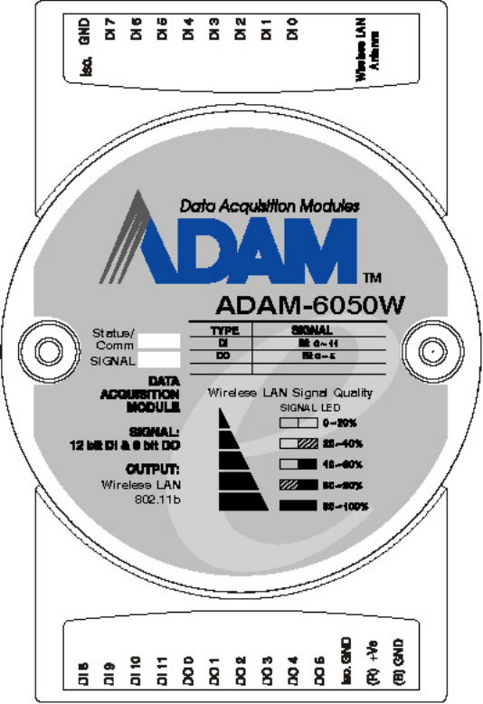
ADAM-6050W 18-channel Digital I/O Module
The ADAM-6050W is a high-density I/O module built-in a IEEE802.11b wireless LAN interface for seamless Ethernet
connectivity. It provides 12 digital input and 6 digital output channels with 5000VRMS Isolating protection. All of the
Digital Input channels support input latch function for important signal handling. Mean while, these DI channels allows
to be used as 1 KHz counter. Opposite to the intelligent DI functions, the Digital Output channels also support pulse
output function.
ADAM-6050W
Figure 1: ADAM-6050W 18-channel Digital I/O Module
ADAM-6050W Specification
Analog Input:
• Channel: 18
• I/O type: 12 DI & 6 DO
• Digital Input: Dry Contact:
Logic level 0: Close to GND
Logic level 1: Open
Wet Contact:
Logic level 0: +3 Vmax Logic level 1: +10 to 30 VDC
• Digital Output:Open Collector to 30 V, 200 mA max. load
• Communication: Wireless LAN IEEE802.11b
• Optical Isolation: 5000VRMS
• Power Consumption: 2 W (Typical)
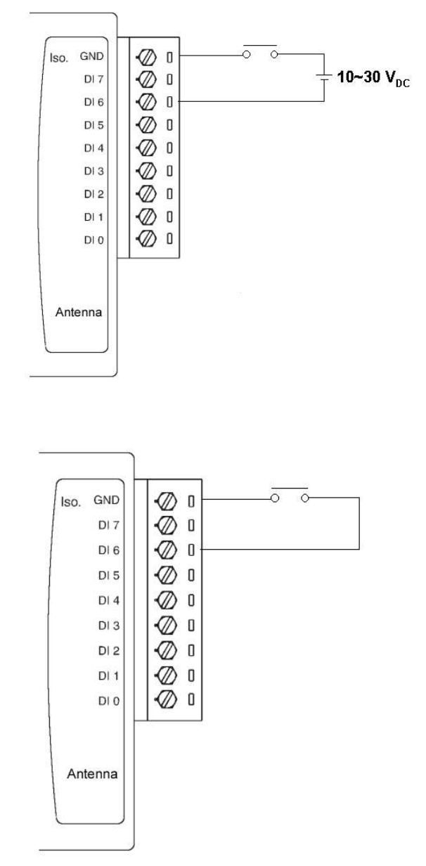
Application Wiring
Figure 2: ADAM-6050W Digital Input (Wet Contact) Wiring
Figure 3: ADAM-6050W Digital Input (Dry Contact) Wiring
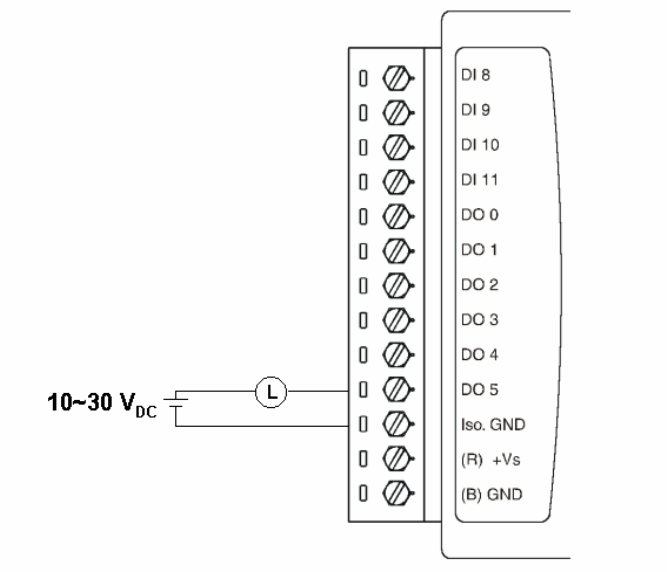
Figure 4: ADAM-6050W Digital Output Wiring
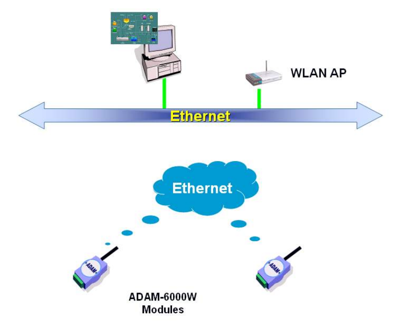
System Architecture
ADAM-6050W Configuration
Network Configuration
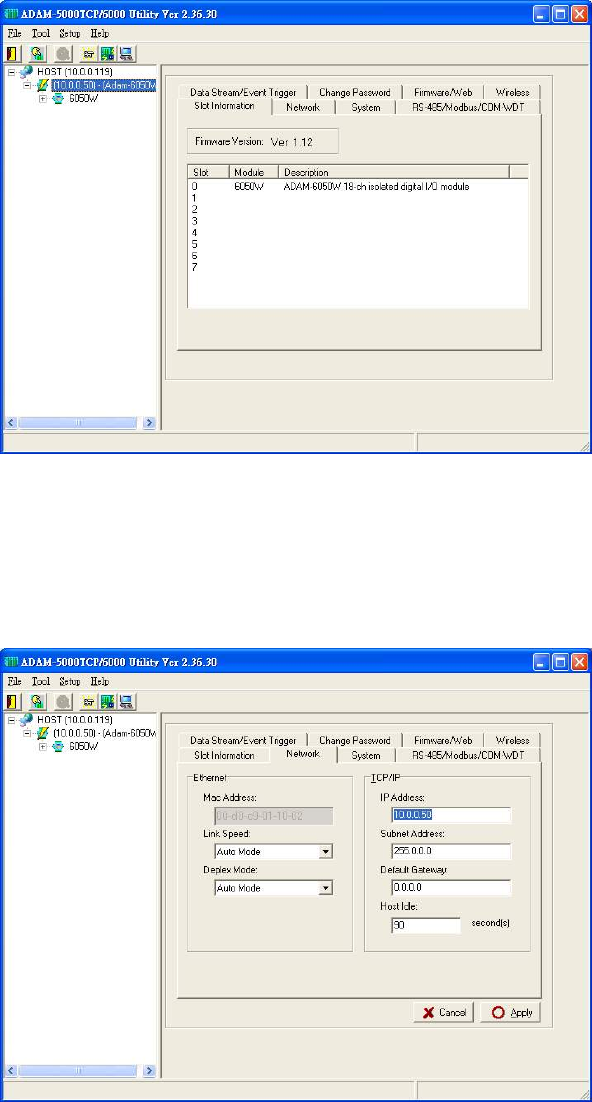
Step 1 : Please open the ADAM-5000TCP-6000 utility software. The utility software will automatically
scan the ADAM-6000 modules. Please wait for the ADAM-6050W being found by utility software.
Step 2 : Please go the “Network” page to change the IP address/Subnet Address/Default Gateway of
ADAM-6050W module to be compatible with user’s existing network and set the host idle time out value
(the ADAM-6000 module can only accept 8 connection from host station. Any host station doesn’t request
the communication with this ADAM-6000 module over the time out setting, the connection of this host
station will be released for the other stations).
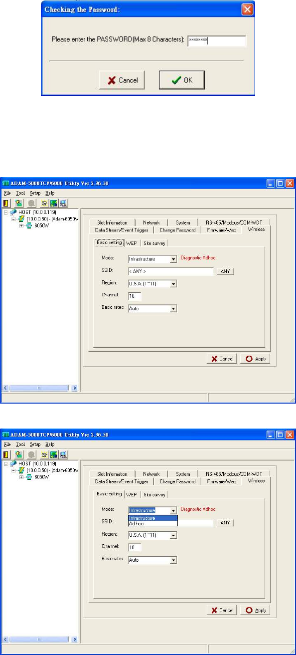
press “Apply” to download the new IP address to ADAM-6050W module (the default password for the
changing configuration is “00000000”).
Step 3 : Re-configuring the IP address of the configuration PC to be the original setting (compatible with
user’s existing network) then re-start the utility software. The software will automatically search the
ADAM-6050W module again.
Step 4 : Go to the “Wireless” page to set the wireless LAN configuration.
Please set the wireless LAN mode to be “Infrastructure” or “Adhoc” based on exact system architecture.
Please assign the SSID for the specific wireless AP to be connected with ADAM-6000W modules. User
can place “ANY” key to let the ADAM-6000W modules to automatically search the existing wireless AP. Or
key in the specific SSID to assign the dedicated AP (strongly recommending to set up the dedicated SSID,
it can guarantee the communication of ADAM-6000W modules to be stable)
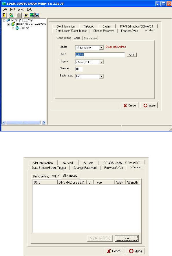
For assigning the dedicated wireless LAN AP, user can use the site survey function to check the existing
AP in connection environment. Please go to the “Site Survey” page.
Press “Scan” bottom to search the existing AP.
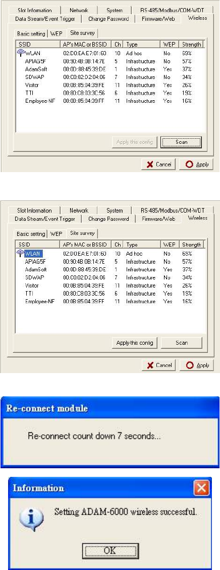
Selecting the AP in the searching result table.
Press “Apply” bottom to accept the AP to finish the set up action.
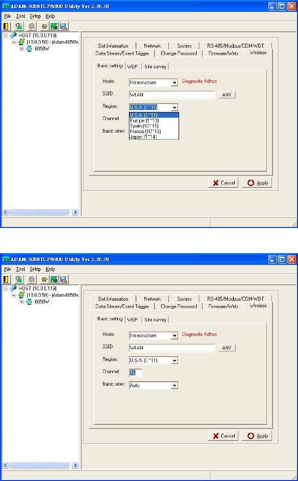
Please select the region for your area.
Setting the used channel, the channel number must be included in the channel segment of your region.
Please select the basic rate for the communication bandwidth.
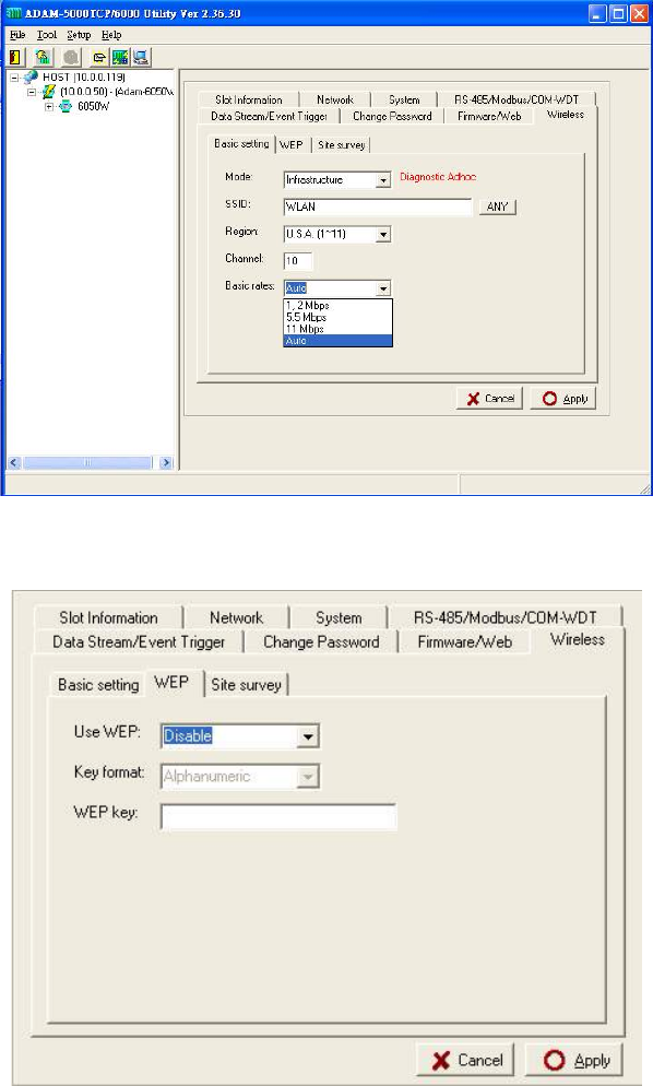
Press the “Apply” bottom to finish the set up work.
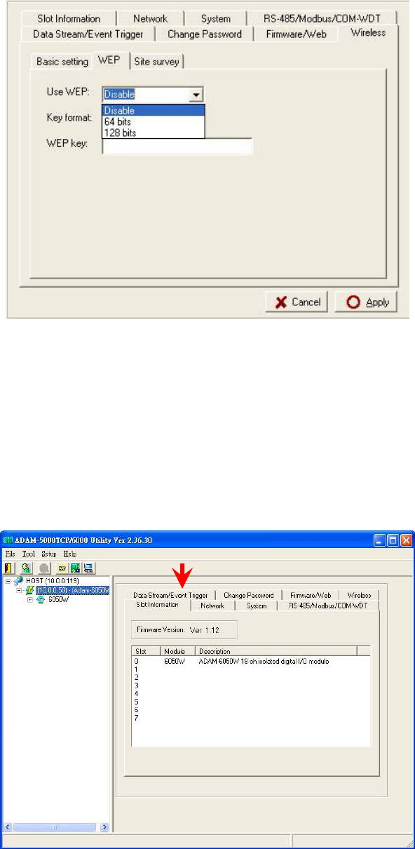
Step 5 : Configure the WEP security setting. Please go to the WEP page in “Wireless” of utility software.
If user want to use the WEP security function, please enable the WEP function in “User WEP” then select
the Key format and key in the WEP key for this requirement.
Step 6 : Data Stream Configuration
In addition to TCP/IP communication protocol, ADAM-6000 supports UDP communication protocol to
regularly broadcast data to specific host PCs.
Click the tab of Data Stream, then configure the broadcasting interval and the specific IP addresses which
need to receive data from the specific ADAM-6000 I/O module. This UDP Data Stream function
broadcasts up to 8 host PCs simultaneously, and the interval is user-defined from 50ms to 7 Days.
Data Stream Monitoring
After finishing the configuration of Data Stream, you can select the item “Monitor Data Stream” in the
function bar or click icon to call up operation display as below Figure.
Select the IP address of the ADAM-6000 you want to read data, then click “Start ” button. The Utility
software will begin to receive the stream data on this operation display.
Firmware/Web Page Configuration
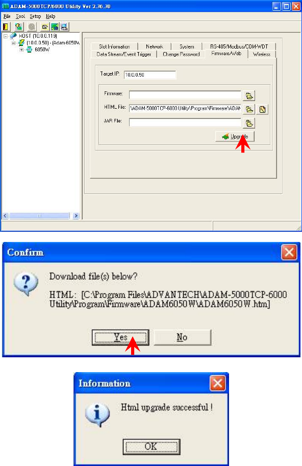
Step 1 : Please go to the “Firmware/Web” configuration page
Step 2 : The ADAM-6000W modules support the configurable web page feature. Users don’t have to
learn the Java language to write the Java program to make the customized web page. Users can use the
utility software to easily configure the web page that you want. Please follow the below instruction to
configure the web page inside ADAM-6000W modules.
Press the web page configuration bottom.
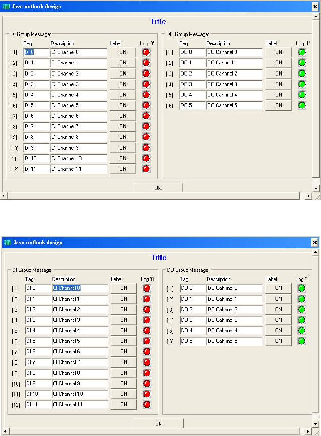
Key in the Tag Name of input channel.
Key in the description of input channel
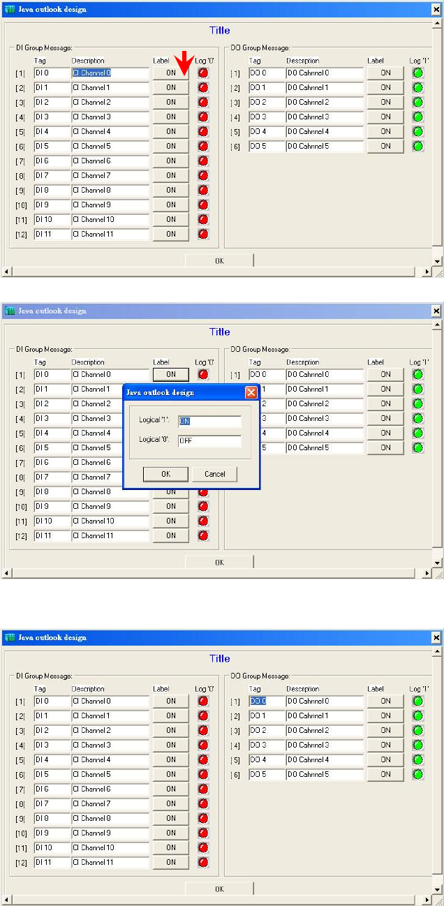
Press the label bottom to configure the label description of input channel.
Key in the Tag Name of output channel
Key in the description of output channel
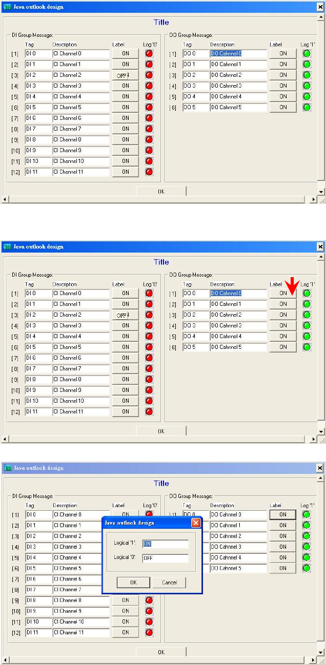
Press the label bottom to configure the label description of output channel
Click the title position to configure the page title description
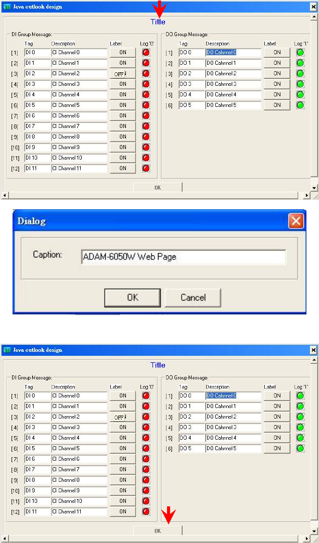
Please press “OK” after finishing all of the web page configuration.
Press “Update” bottom to download the web page configuration into ADAM-6000W module. And system
will save the configuration data as a file in C:\Programs\ADAM-5000TCP-6000
Utility\Program\Firmware\ADAM-6050W\ADAM6050W.Html
User can also retrieve the previous web page configuration file to download to ADAM-6000W Module.
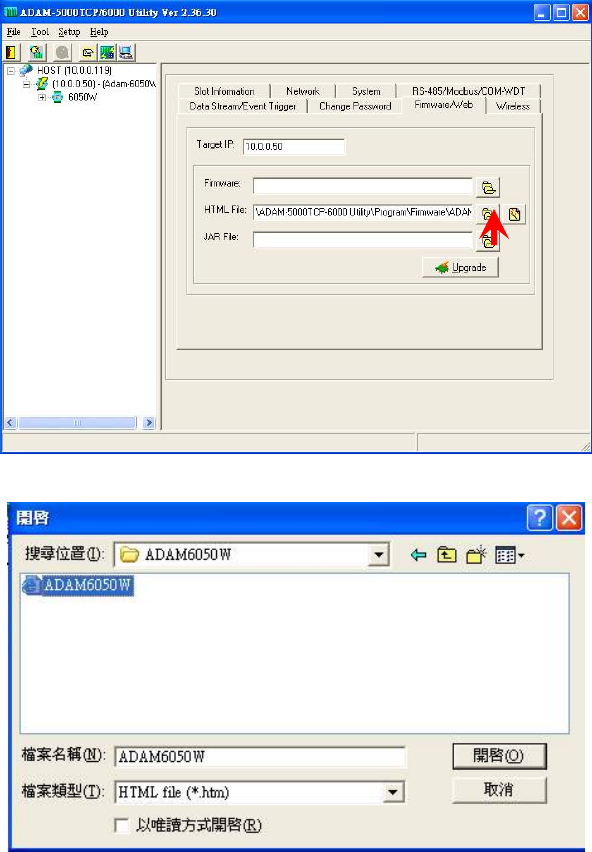
Select the stored web page configuration file then press “Open”
Follow the above action to download the selected file into ADAM-6000W module.
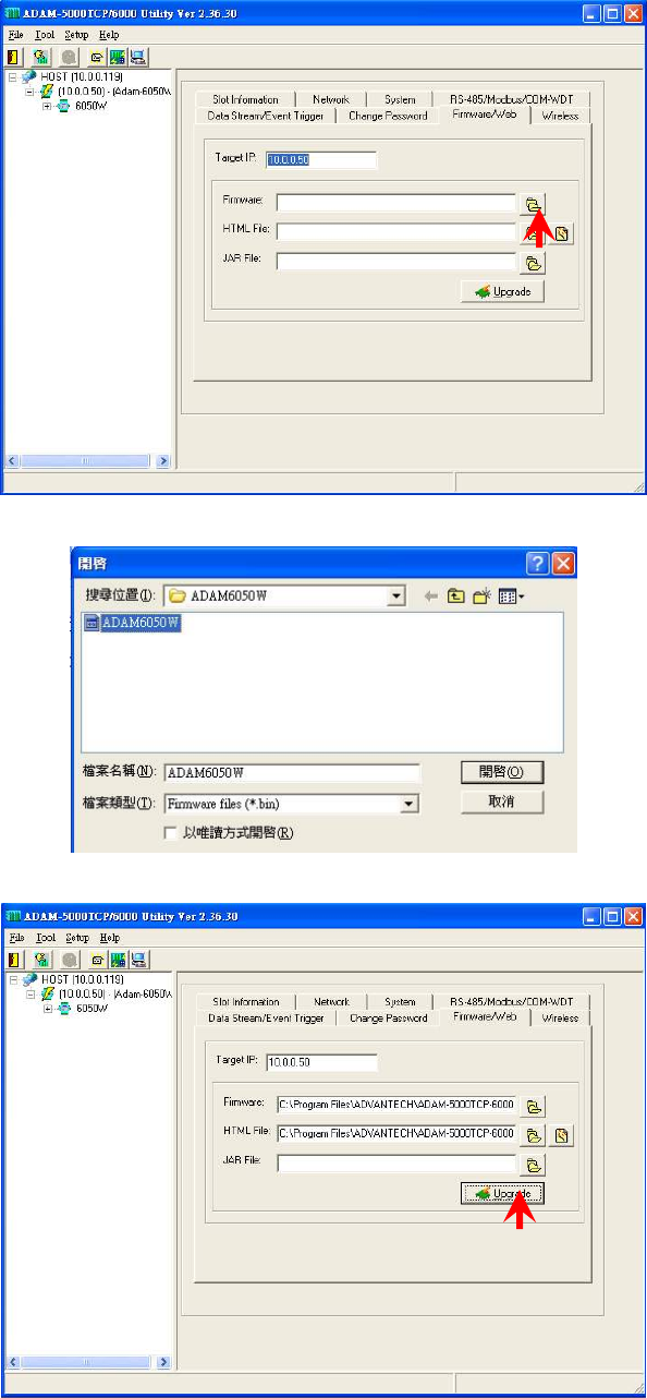
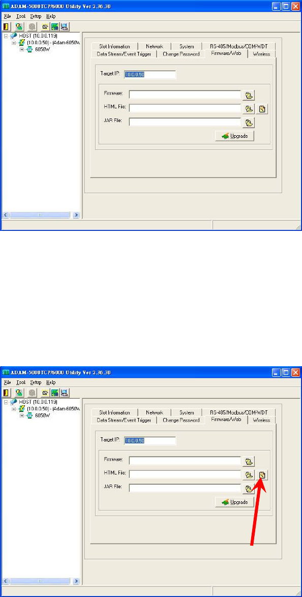
Firmware Update
Step 1 : Press the browse bottom of firmware
Step 2 : Select the firmware file to be downloaded
Step 3 : Press “Update” bottom to finish the firmware update action
Input/Output Channel Configuration
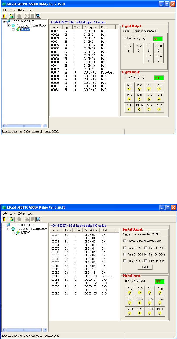
Step 1 : Please click on the “6050W” to go to the ADAM-6050W configuration main page.
Step 7 : Please go to “Communication WDT” to set up the communication watchdog timer setting. This
function is used for security protect, it means sometimes, noise or other reasons will cause the
communication fail, and the host PC won’t control the modules anymore, but the modules will keep the
latest output status, and this status may cause dangerous, so while this situation happen, the
communication WDT will detect it till timeout then reset the module and set the output to safety value to
prevent the dangerous, user can set the safety value by themselves.
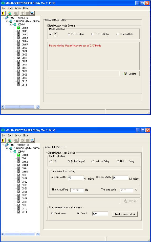
Step 3 : Please click on “DO:XX” to access the digital output channel configuration page. The digital
output channel of ADAM-6050W can be configured as typical DO output, pulse output, DO with LO to Hi
delay or DO with Hi to LO delay:
For typical DO setting :
For Pulse Output setting :
User can set the Lo/Hi sign width based on exact requirement. The pulse output also support the
limited count and continuous pulse output (please select this function in the block of “How Many
Pulse Count to Output”.
Please click the “Update” to download the configuration into ADAM-6050W module then clicking the
“To start pulse output” to initiate the pulse output action.
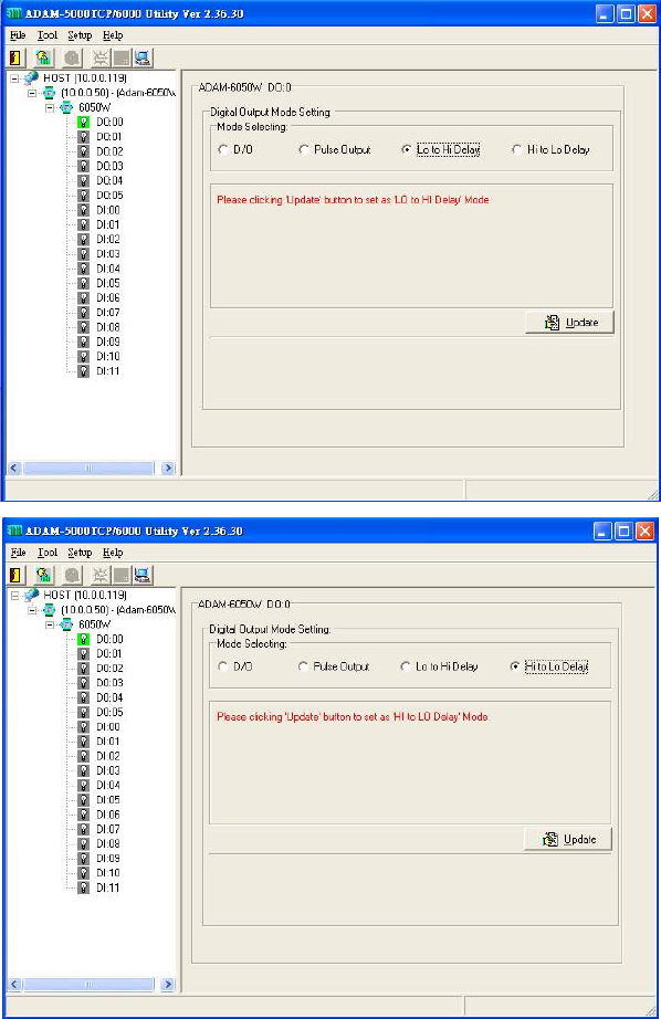
For “Lo to Hi delay” and “Hi to Lo delay” function :
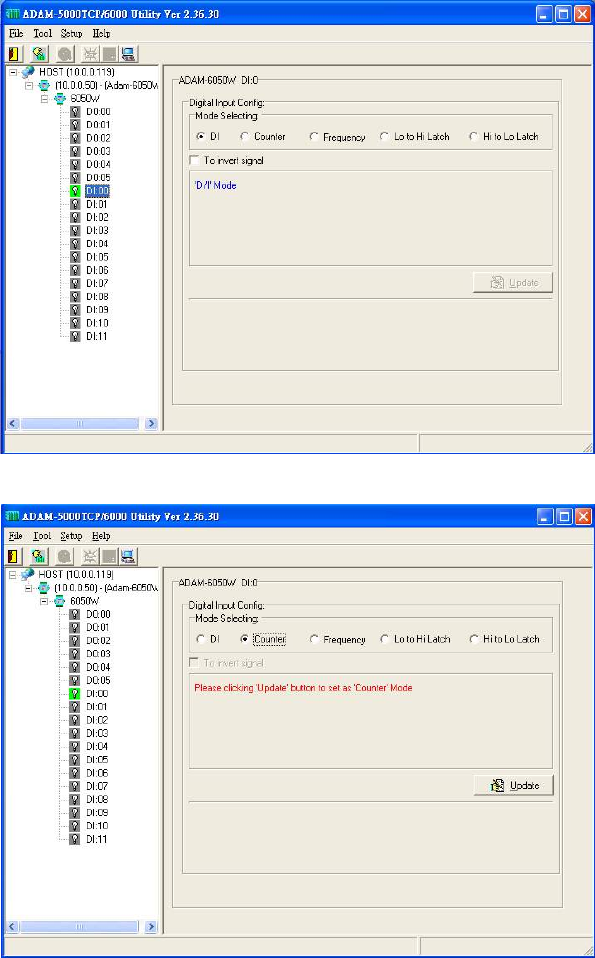
Step 4 : Please click on “DI:XX” to access the digital input configuration page. The digital input channel of
ADAM-6068 supports typical DI, counter, frequency, Lo to Hi Latch and Hi to Lo Latch.
For typical DI setting :
For Counter setting :
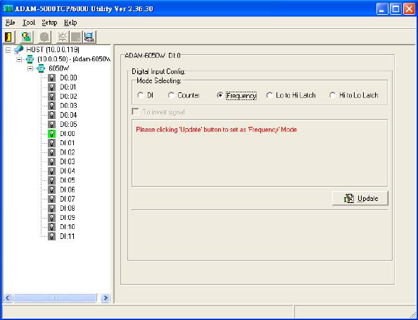
For Frequency setting :
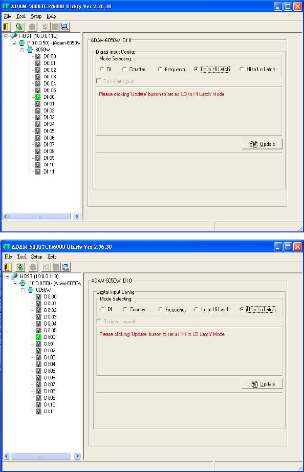
For “Lo to Hi Latch” and “Hi to Lo Latch” setting :
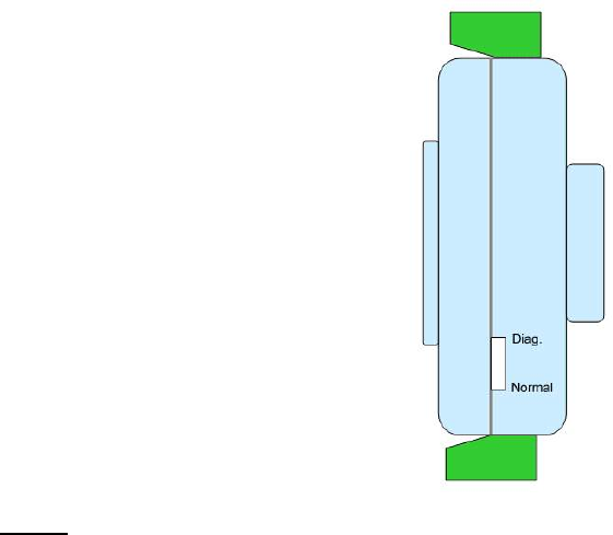
Appendix : Adam-6000W Mode Setting
switch
Mode 1 (Normal Mode): In this mode, you can use Utility to configure module to Infrastructure or Ad hoc
mode.
Mode 2 (Diagnostic Mode): The purpose of this mode is used to recover the Adam-6000W module from
error state. User can switch module to diagnostic Infrastructure/Ad hoc mode that
has temporary wireless setting and default IP, subnet mask. Therefore, user can
re-configure the wireless setting when module’s communication is dead. (*Note:
the temporary wireless setting will be cleared after reboot to Normal mode)
Diagnostic-mode default settings:
Diagnostic Ad hoc mode setting:
Temporary SSID: WLAN
Temporary Channel: 10
Temporary Wep: No
IP: 10.0.0.1
Subnet mask: 255.0.0.0
Gateway: 0.0.0.0
Diagnostic Infrastructure mode setting:
Temporary SSID: <ANY>
Temporary Channel: 10
Temporary Wep: No
IP: 10.0.0.1
Subnet mask: 255.0.0.0
Gateway: 0.0.0.0

Assigning addresses for the ADAM-6050W Modules
ADDR 0X CH ITEM Attribute ADDR 4X CH ITEM Attribute
00001 0 DI R 40001~40002 0 *Counter R
00002 1 DI R 40003~40004 1 *Counter R
00003 2 DI R 40005~40006 2 *Counter R
00004 3 DI R 40007~40008 3 *Counter R
00005 4 DI R 40009~40010 4 *Counter R
00006 5 DI R 40011~40012 5 *Counter R
00007 6 DI R 40013~40014 6 *Counter R
00008 7 DI R 40015~40016 7 *Counter R
00009 8 DI R 40017~40018 8 *Counter R
00010 9 DI R 40019~40020 9 *Counter R
00011 10 DI R 40021~40022 10 *Counter R
00012 11 DI R 40023~40024 11 *Counter R
00017 0 DO R/W 40025~40026 0 Pulse Output
Low Level R
00018 1 DO R/W 40027~40028 1 Pulse Output
Low Level R
00019 2 DO R/W 40029~40030 0 Pulse Output
Low Level R
00020 3 DO R/W 40031~40032 1 Pulse Output
Low Level R
00021 4 DO R/W 40033~40034 0 Pulse Output
Low Level R
00022 5 DO R/W 40035~40036 1 Pulse Output
Low Level R
00033 0 Counter
Start(1)/Stop(0) R/W 40037~40038 0 Pulse Output
High Level R
00034 0 Clear Counter(1) R/W 40039~40040 1 Pulse Output
High Level R
00035 0 Clear Overflow R/W 40041~40042 2 Pulse Output
High Level
00036 0
Latch Status/ Clear
Status R/W 40043~40044 3 Pulse Output
High Level
00037 1 Counter
Start(1)/Stop(0) R/W 40045~40046 4 Pulse Output
High Level R
00038 1 Clear Counter(1) R/W 40047~40048 5 Pulse Output
High Level R
00039 1 Clear Overflow R/W
00040 1
Latch Status/ Clear
Status R/W
00041 2 Counter
Start(1)/Stop(0) R/W

00042 2 Clear Counter(1) R/W 40049~40050 0 Set Absolute Pulse
(0=Continue Mode) R
00043 2 Clear Overflow R/W 40051~40052 1 Set Absolute Pulse
(0=Continue Mode) R
00044 2
Latch Status/ Clear
Status R/W 40053~40054 2
Set Absolute Pulse
(0=Continue Mode) R
00045 3 Counter
Start(1)/Stop(0) R/W 40055~40056 3
Set Absolute Pulse
(0=Continue Mode) R
00046 3 Clear Counter(1) R/W 40057~40058 4 Set Absolute Pulse
(0=Continue Mode) R
00047 3 Clear Overflow R/W 40059~40060 5 Set Absolute Pulse
(0=Continue Mode) R
00048 3
Latch Status/ Clear
Status R/W
00049 4 Counter
Start(1)/Stop(0) R/W
00050 4 Clear Counter(1) R/W 40061~40062 0 Set Incremental
Pulse R
00051 4 Clear Overflow R/W 40063~40064 1
Set Incremental
Pulse R
00052 4
Latch Status/ Clear
Status R/W 40065~40066 2 Set Incremental
Pulse R
00053 5 Counter
Start(1)/Stop(0) R/W 40067~40068 3 Set Incremental
Pulse R
00054 5 Clear Counter(1) R/W 40069~40070 4 Set Incremental
Pulse R
00055 5 Clear Overflow R/W 40071~40072 5 Set Incremental
Pulse R
00056 5
Latch Status/ Clear
Status R/W
00057 6 Counter
Start(1)/Stop(0) R/W
00058 6 Clear Counter(1) R/W
00059 6 Clear Overflow R/W
00060 6
Latch Status/ Clear
Status R/W
00051 7 Counter
Start(1)/Stop(0) R/W
00062 7 Clear Counter(1) R/W
00063 7 Clear Overflow R/W
00064 7
Latch Status/ Clear
Status R/W
00065 8 Counter
Start(1)/Stop(0) R/W
00066 8 Clear Counter(1) R/W
00067 8 Clear Overflow R/W
00068 8
Latch Status/ Clear
Status R/W
00069 9 Counter
Start(1)/Stop(0) R/W
00070 9 Clear Counter(1) R/W

00071 9 Clear Overflow R/W
00072 9
Latch Status/ Clear
Status R/W
00073 10 Counter
Start(1)/Stop(0) R/W
00074 10 Clear Counter(1) R/W
00075 10 Clear Overflow R/W
00076 10
Latch Status/ Clear
Status R/W
00077 11 Counter
Start(1)/Stop(0) R/W
00078 11 Clear Counter(1) R/W
00079 11 Clear Overflow R/W
00080 11
Latch Status/ Clear
Status R/W
*Note : How to retrieve the counter/frequency value on Modbus address mapping
Example :
Counter(dec) = (value of 40002) x 65536 + (value of 40001)
Frequency(dec) = (value of 40001)/10 Hz

This equipment has been tested and found to comply with the limits for a Class B digital device,
pursuant to part 15 of the FCC rules. These limits are designed to provide reasonable protection
against harmful interference in a residential installation. This equipment generates, uses and can
radiate radio frequency energy and, if not installed and used in accordance with the instructions,
may cause harmful interference to radio communications. However, there is no guarantee that
interference will not occur in a particular installation. If this equipment does cause harmful
interference to radio or television reception, which can be determined by turning the equipment off
and on, the user is encouraged to try to correct the interference by one or more of the following
measures:
-Reorient or relocate the receiving antenna.
-Increase the separation between the equipment and receiver.
-Connect the equipment into an outlet on a circuit different from that to which the receiver is
connected.
-Consult the dealer or an experienced radio/TV technician for help.
This Transmitter must not be co-located or operating in conjunction with any other antenna or
transmitter.
Any changes or modifications (including the antennas) made to this device that are not expressly
approved by the manufacturer may void the user’s authority to operate the equipment.
This equipment complies with FCC RF radiation exposure limits set forth for an uncontrolled
environment. This equipment should be installed and operated with a minimum distance of 20
centimeters between the radiator and your body.
CE Declaration of Conformity
!
0984
Is herewith confirmed to comply with the requirements set out in the Council Directive on
the Approximation of the Laws of the Member States relating to Electromagnetic
Compatibility (89/336/EEC), Low-voltage Directive (73/23/EEC) and the Amendment
Directive (93/68/EEC), the procedures given in European Council Directive 99/5/EC and
89/3360EEC.
The equipment was passed. The test was performed according to the following European
standards:
EN 300 328 V.1.6.1 (2004-04)
EN 301 489-1 V.1.4.1 (2002-04) / EN 301 489-17 V.1.2.1 (2002-04)
EN 50371: 2002
EN 60950: 2000