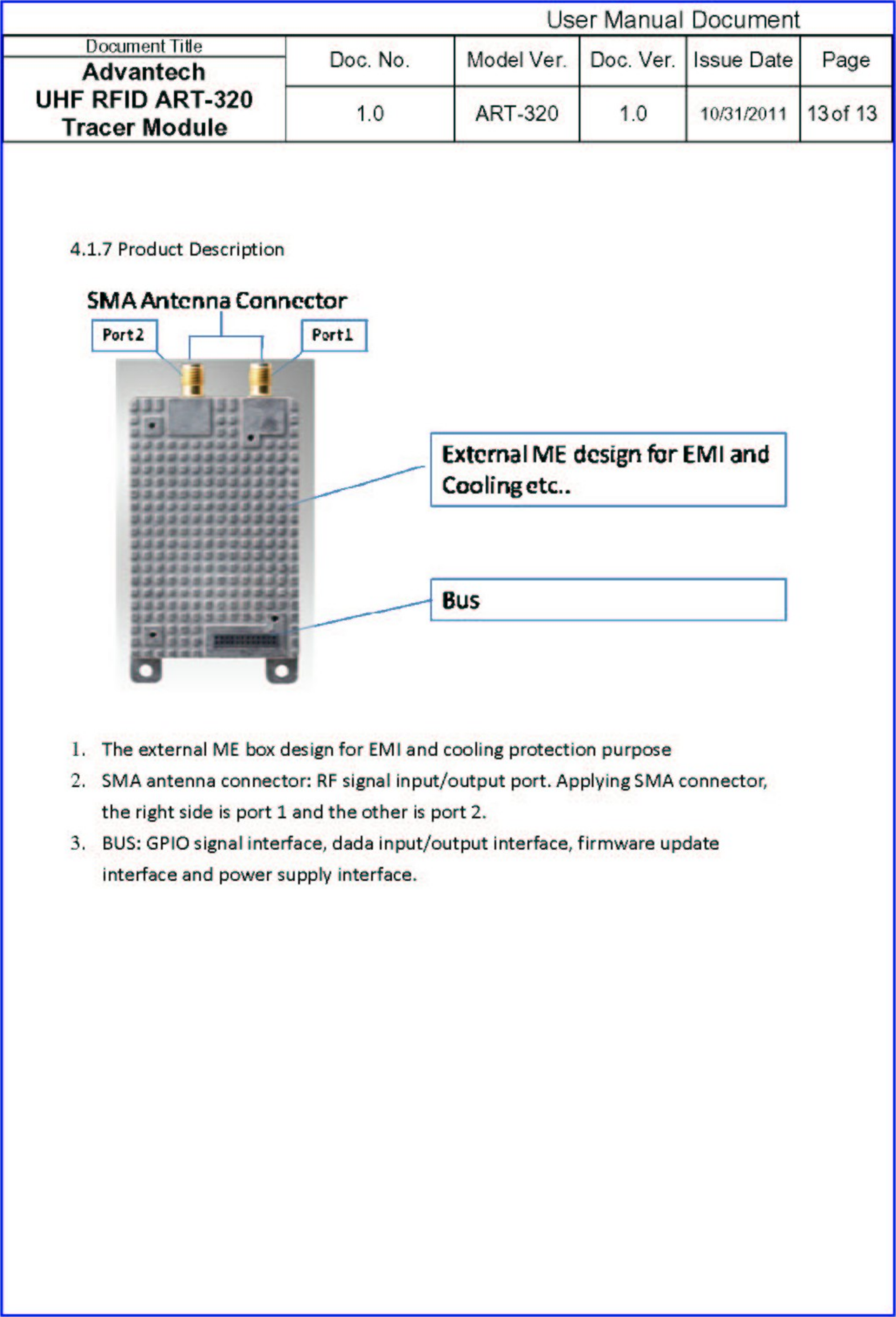
Advantech Co ART-320 UHF RFID ART-320 Tracer Module User Manual

Advantech Co Ltd UHF RFID ART-320 Tracer Module

User Manual

 User Manual Document Document Title  Doc. No.  Model Ver. Doc. Ver.  Issue Date Page Advantech  UHF RFID ART-320 Tracer Module  1.0 ART-320 1.0 10/31/2011 1 of 13   Advantech  UHF RFID ART-320 Tracer Module ART-320 User Manual
 User Manual Document Document Title  Doc. No.  Model Ver. Doc. Ver.  Issue Date Page Advantech  UHF RFID ART-320 Tracer Module  1.0 ART-320 1.0 10/31/2011 2 of 13  1 SCOPE.................................................................................................................................................................3 2 THE LIST OF REFERENCES: ........................................................................................................................5 3 ABBREVIATED TERMS..................................................................................................................................5 4 SYSTEM SPECIFICATION .............................................................................................................................6 4.1 SYSTEM STRUCTURE ....................................................................................................................................7 4.1.1 Radio Frequency Circuit.........................................................................................................................8 4.1.2 The Interface of Power Supplies.............................................................................................................9 4.1.3 Hardware User Manual..........................................................................................................................9 4.1.4 Module Operation.................................................................................................................................10 4.1.5 Interfacing with ART-320 Module ........................................................................................................ 11 4.1.6 Starting Windows Demo Program ........................................................................................................12
 User Manual Document Document Title  Doc. No.  Model Ver. Doc. Ver.  Issue Date Page Advantech  UHF RFID ART-320 Tracer Module  1.0 ART-320 1.0 10/31/2011 3 of 13   1  Scope Radio Frequency Identification (RFID) has been included in the 21st century one of the 10 major technologies. RF is the automatic identification object recognition technology. Readers are to read in the attached electronic tags on objects such as to carry out card access to the information, animal tracking, checking inventory and merchandise checkout, and sales of the whole supply chain management. This will become a model to change human consumption patterns emerging technology. The main operation principle of RFID is utilizing the reading device (Reader) Send RF wave for the electronic label that is planted into or stuck on the things (Tag) in order to distinguish the wireless materials. The composition component of RFID system includes Reader, Tag, PAD or cell-phone and the contents which are in reader or tag. When the application system wants to distinguishing things, the host can be passed by RS-232 to control reader and sends radio wave energy. When Tag senses this energy that there is asking the answering machine inside (Transponder) and the mechanism will change power into energy that passes a series of discernment materials giving back to reader and host that are in order to distinguish the things. The specification of ART-320 is in compliance with EPC Class-1 Gen 2 that is a specification for RFID air interface. The changes or modifications not expressly approved by the party responsible for compliance could void the user’s authority to operate the equipment. Note: This equipment has been tested and found to comply with the limits for a Class B Digital Device, pursuant to part 15 of the FCC Rules. These limits are designed to provide reasonable protection against harmful interference in a residential installation. This equipment generates, uses and can radiate radio frequency energy and, if not installed and used in accordance with the instruction, may cause harmful interference to radio communication. However, there is no grantee that interference will not occur in a particular installation. If this equipment dose cause harmful interference to radio or television reception, which can be determined by turning the equipment off and on , the user is encouraged to try to correct the interference by one or more of the following measures: --Reorient or relocate the receiving antenna.
 User Manual Document Document Title  Doc. No.  Model Ver. Doc. Ver.  Issue Date Page Advantech  UHF RFID ART-320 Tracer Module  1.0 ART-320 1.0 10/31/2011 4 of 13  --Increase the separation between the equipment and receiver. --Connect the equipment into an outlet on a circuit different from that to     which the receiver is connected. --Consult the dealer or an experienced radio/TV technician for help.
 User Manual Document Document Title  Doc. No.  Model Ver. Doc. Ver.  Issue Date Page Advantech  UHF RFID ART-320 Tracer Module  1.0 ART-320 1.0 10/31/2011 5 of 13   2  The list of references:  Item  Referances 1  EPC Class-1 Generation-2 UHF RFID version 1.1.02 ISO/IEC WD 18000-6C Table 1 3  Abbreviated Terms  Term Definitions ASK Amplitude-Shift Keying EPC  Electronic Product Code PIE  Pulse Interval Encoding ppm Parts-per-million PSK Phase-Shift Keying Reader Interrogator RF Radio Frequency RFID  Radio Frequency Identification TAG Transponder IC FW Firmware Table 2
 User Manual Document Document Title  Doc. No.  Model Ver. Doc. Ver.  Issue Date Page Advantech  UHF RFID ART-320 Tracer Module  1.0 ART-320 1.0 10/31/2011 6 of 13   4  System Specification Reader is mainly used to read the materials from tag to carry on the work of distinguishing of the things with PDA or the cell-phone. When PDA or the cell-phone assigns the order for Reader, reader will transmit RF wave with data out through antenna. Once tags are receiving the information, the tag will backscatter the data with 96-bit EPC C1G2 protocol to Reader through RF mechanism that is built inside. Reader receives after the data that will give PDA or the cell-phone the work of distinguishing which carries on the things. For the wired RS232 interface of entity among PDA, cell-phone and readers, the industrial communication protocols are interchanging in order to reach the data. It is depending on the untouchable RF wave between reader and tag to reach the data to interchange with the communication protocol that is defined by EPC C1G2。 The Fig 4-1 is a data flow chart. It is including Reader, PDA and cell-phone communication code of protocol during the encoding and decoding. The code of the communication protocol between Reader and Tag is operated with decoding.。Host Protocol Encode Tag Protocol DecodeHost Protocol Decode Tag Protocol EncodeCommand ControlHostControllerHost Protocol ResponseHost Protocol RequestTagTag Protocol DecodeTag Protocol RequestREADER Fig 4-1. Data Flow Chart
 User Manual Document Document Title  Doc. No.  Model Ver. Doc. Ver.  Issue Date Page Advantech  UHF RFID ART-320 Tracer Module  1.0 ART-320 1.0 10/31/2011 7 of 13  4.1 System Structure The Fig 4-2 and Fig 4-3 show between the hardware configuration and user interface of the ART-320. There are five parts of PDA or the cell-phone for system structures that are including the power, digit, radio frequency, base and FW respectively.  Fig 4-2. The Block Diagram of ART-320
 User Manual Document Document Title  Doc. No.  Model Ver. Doc. Ver.  Issue Date Page Advantech  UHF RFID ART-320 Tracer Module  1.0 ART-320 1.0 10/31/2011 8 of 13  Watchdog UARTRx, Tx ADCTimerRF Control TAG Reply Manage PIE Generator PWMEPC Class-1 GEN-2 Command HandleEEPROMExternal InterruptPower ControlSystem ManageTimeOut ControlCommand Handle Fig 4-3. Micro-Control Unit Block Diagram 4.1.1 Radio Frequency Circuit This is a transceiver module with ISM of the electromagnetic wave for a transmission and receiving. It is among them transceiver inside that is in transmitter and the receiver function as follows:  The function of the Transmitter:   The function of the transmitter is controlled and produced the signal carrier by the synthesizer of the microprocessor. The signal that will be modulated in amplitude to be an ASK signal used to offer the power that the tag is used to read data from its memory as well as using the pulse to adjust the way of changing to write the data into the tag。  The function of the Receiver:   The function in receiving information from tags has been demodulated to several digital signals. The signals are also amplified and straining waves to deal with microprocessor.
 User Manual Document Document Title  Doc. No.  Model Ver. Doc. Ver.  Issue Date Page Advantech  UHF RFID ART-320 Tracer Module  1.0 ART-320 1.0 10/31/2011 9 of 13  4.1.2  The Interface of Power Supplies The power system is offered 3.3V by ART-320 interface of PDA or the cell-phone with Max. 2A.  3.3V-5.2.5 (1)  :The microprocessor and UART using.   3.3V-5.2.5 (2)  :ISM RF transceiver using.  3.3V-5.2.5 (3)  :Power Amplify using      4.1.3 Hardware User Manual  The ART-320 connects to the host via a 16 pins header for data, communications and 4-pin header for power. The 3 data lines are: Ground, Data Transmit (TX) and Data receive (RX) for UART. The communication header also contains the additional pins which are interfaces for JTAG. Those pins can be used to provide data to another sensor or auxiliary board. The power header pins supplying power to the ART-320 is 3.3 Volts (and must be low-noise and regulated). A diagram of the pins are given below.
 User Manual Document Document Title  Doc. No.  Model Ver. Doc. Ver.  Issue Date Page Advantech  UHF RFID ART-320 Tracer Module  1.0 ART-320 1.0 10/31/2011 10 of 13   Fig 4-4. Pin Out for ART-320   Fig 4-5. Photograph of ART-320 4.1.4 Module  Operation   The ART-320 is a dual-antenna reader module. The backscatter signal is demodulated to baseband through a standard mixer stage and is filtered and amplified. The baseband signal is then sampled and processed by a microcontroller.   The entire RF section of the reader module can be completely turned OFF under software control by the microcontroller. This allows the ART-320 to consume very low power when in standby mode. During RFID operation, the transmit power of the ART-320 is 1W, so the total power consumption is 1.8A during the
 User Manual Document Document Title  Doc. No.  Model Ver. Doc. Ver.  Issue Date Page Advantech  UHF RFID ART-320 Tracer Module  1.0 ART-320 1.0 10/31/2011 11 of 13  fraction of a second that is required to read the tags in the field. A block diagram of module is given in Fig 4-6.   Fig 4-6. ART-320 Block Diagram 4.1.5 Interfacing  with ART-320 The ART-320 is designed to interface with another circuit board and communicate using a simple 3-wire serial interface. However, for testing purposes, it is possible to connect the ART-320 to a computer using a serial RS-232 adapter. In this case, the Advantech RFID Utility software can be used.
 User Manual Document Document Title  Doc. No.  Model Ver. Doc. Ver.  Issue Date Page Advantech  UHF RFID ART-320 Tracer Module  1.0 ART-320 1.0 10/31/2011 12 of 13   4.1.6 Starting Windows Demo Program After installing the demo program, you can connect the reader to the computer using a serial cable (standard DB9 connectors). Please make sure that you have an antenna connected to the reader.   The program supplied with the kit is able to interface to all the RFID readers made by Advantech. You should open the program (Advantech RFID Utility), then go to the Inventory menu and selected . Then go to the Connection menu and select the proper COM port where you connected the reader, you can click the CONNECT button. After you run the program for the first time, the software settings will be saved automatically so you should not need to reconfigure the control program unless you switch to another reader product.
Manufacturer Company: Advantech Co., Ltd. Address: No.1, Alley 20, Lane 26, Rueiguang Road, Neihu District, Taipei 114, Taiwan, R.O.C. 15.105 Class B digital device or   This equipment has been tested and found to comply with the limits for a Class B digital device, pursuant to Part 15 of the FCC Rules. These limits are designed to provide reasonable protection against harmful interference in a residential installation. This equipment generates, uses and can radiate radio frequency energy and, if not installed and used in accordance with the instructions, may cause harmful interference to radio communications. However, there is no guarantee that interference will not occur in a particular installation. If this equipment does cause harmful interference to radio or television reception, which can be determined by turning the equipment off and on, the user is encouraged to try to correct the interference by one of the following measures:   FCC Caution: Any changes or modifications not expressly approved by the party responsible for compliance could void the user's authority to operate this equipment.    15.19 Labeling   This device complies with Part 15 of the FCC Rules. Operation is subject to the following two conditions: (1) This device may not cause harmful interference, and (2) this device must accept any interference received, including interference that may cause undesired operation   IMPORTANT NOTE: FCC Radiation Exposure Statement: This equipment complies with FCC radiation exposure limits set forth for an uncontrolled environment. This equipment should be installed and operated with minimum distance 20cm between the radiator & your body.      Reorient or relocate the receiving antenna.    Increase the separation between the equipment and receiver.    Connect the equipment into an outlet on a circuit different from that to which the receiver is connected.  Consult the dealer or an experienced radio/TV technician for help. Model: ART-320  FCC ID: M82-ART-320    This device complies with Part 15 of FCC Rules. Operation is subject to the following two conditions: (1)this device may not cause harmful interference, and (2)this device must accept any interference received, including interference that may cause undesired operation.

Navigation menu