Advantech Co DLV6210 Computer User Manual
Advantech Co Ltd Computer
UserManual.wiki
>
Advantech Co
>
DLV6210 User Manual
User manual
Navigation menu
Upload a User Manual
Namespaces
Wiki Guide
HTML
PDF
Info
Views
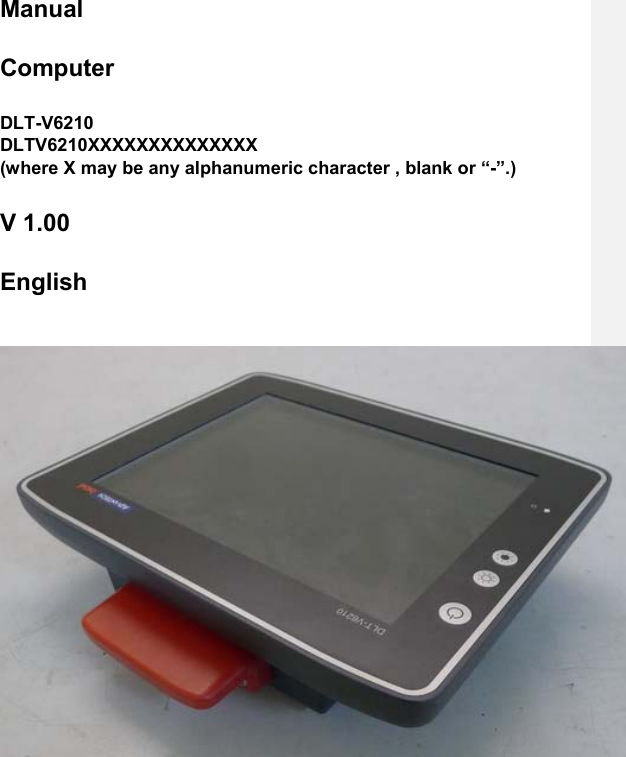
User Manual
Discussion / Help
Navigation
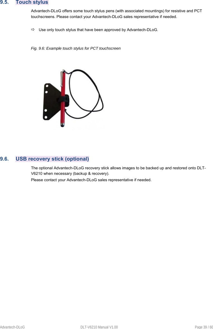
![Page 50 / 60 DLT-V6210 Manual V1.00 Advantech-DLoG 15. Guidelines and certificates 15.1. FCC USA/CAN DLoG GmbH Germany indicated that the radiated emission of DLT-V6210 complies with the requirements set forth in Subpart B of Part 15 of the Federal Communication Commission (FCC) rules for Class B devices and the Canadian Interference-Causing Equipment Standard ICES-003 for digital apparatus. This equipment generates, uses and can radiate radio frequency energy and, if not installed and used in accordance with the instructions, may cause harmful interference to radio communications. However, there is no guarantee that interference will not occur in a particular installation. If this equipment does cause harmful interference to radio or television reception, which can be determined by turning the equipment off and on, the user is encouraged to try to correct the interference by one or more of the following measures: Reorient or relocate the receiving antenna. Increase the separation between the equipment and receiver. Connect the equipment into an outlet on a circuit different from that to which the receiver is connected. Consult the dealer or an experienced radio/TV technician for help. CAUTION Any change or modification which is not expressly approved in the corresponding pages can lead to the withdrawal of the operating license for this device. 15.1. RED (Radio Equipment Directive) 2014/53/EU With regard to the RED (Radio Equipment Directive) 2014/53/EU the statements as below in the declaration of conformity for DLT-V6210 industrial PC to apply. Česky [Czech]: Toto zařízení je v souladu se základními požadavky a ostatními odpovídajícími ustanoveními Směrnice 2014/53/EU. Dansk [Danish]: Dette udstyr er i overensstemmelse med de væsentlige krav og andre relevante bestemmelser i Direktiv 2014/53/EU. Deutsch [German]: Dieses Gerät entspricht den grundlegenden Anforderungen und den weiteren entsprechenden Vorgaben der Richtlinie 2014/53/EU. Eesti [Estonian]: See seade vastab direktiivi 2014/53/EU (EÜ) olulistele nõuetele ja teistele asjakohastele sätetele. English: This equipment is in compliance with the essential requirements and other relevant provisions of Directive 2014/53/EU. Español [Spanish]: Este equipo cumple con los requisitos esenciales asi como con otras disposiciones de la Directiva 2014/53/EU (CE). Ελληνική [Greek]: Αυτός ο εξοπλισµός είναι σε συµµόρφωση µε τις ουσιώδεις απαιτήσεις και άλλες σχετικές διατάξεις της Οδηγίας 2014/53/EU. Français [French]: Cet appareil est conforme aux exigences essentielles et aux autres dispositions pertinentes de la Directive 2014/53/EU.](https://usermanual.wiki/Advantech-Co/DLV6210/User-Guide-3338157-Page-52.png)
![Advantech-DLoG DLT-V6210 Manual V1.00 Page 51 / 60 Íslenska [Icelandic]: Þetta tæki er samkvæmt grunnkröfum og öðrum viðeigandi ákvæðum Tilskipunar 2014/53/EU. Italiano [Italian]: Questo apparato é conforme ai requisiti essenziali ed agli altri principi sanciti dalla Direttiva 2014/53/EU (CE). Latviski [Latvian]: Šī iekārta atbilst Direktīvas 2014/53/EU (EK) būtiskajām prasībām un citiem ar to saistītajiem noteikumiem. Lietuvių [Lithuanian]: Šis įrenginys tenkina 2014/53/EU (EB) Direktyvos esminius reikalavimus ir kitas šios direktyvos nuostatas. Nederlands [Dutch]: Dit apparaat voldoet aan de essentiele eisen en andere van toepassing zijnde bepalingen van de Richtlijn 2014/53/EU. Malti [Maltese]: Dan l-apparat huwa konformi mal-ħtiġiet essenzjali u l-provedimenti l-oħra rilevanti tad-Direttiva 2014/53/EU. Magyar [Hungarian]: Ez a készülék teljesíti az alapvető követelményeket és más 2014/53/EU (EK) irányelvben meghatározott vonatkozó rendelkezéseket. Norsk Norwegian]: Dette utstyret er i samsvar med de grunnleggende krav og andre relevante bestemmelser i EU-direktiv 2014/53/EU (EF). Polski [Polish]: Urządzenie jest zgodne z ogólnymi wymaganiami oraz szczególnymi warunkami określonymi Dyrektywą UE: 2014/53/EU. Português [Portuguese]: Este equipamento está em conformidade com os requisitos essenciais e outras provisões relevantes da Directiva 2014/53/EU. Slovensko [Slovenian]: Ta naprava je skladna z bistvenimi zahtevami in ostalimi relevantnimi pogoji Direktive 2014/53/EU. Slovensky [Slovak]: Toto zariadenie je v zhode so základnými požiadavkami a inými príslušnými nariadeniami direktív: 2014/53/EU. Suomi [Finnish]: Tämä laite täyttää direktiivin 2014/53/EU (EY) olennaiset vaatimukset ja on siinä asetettujen muiden laitetta koskevien määräysten mukainen. Svenska [Swedish]: Denna utrustning är i överensstämmelse med de väsentliga kraven och andra relevanta bestämmelser i Direktiv 2014/53/EU. Wi-Fi special regulations for Germany and France For DLT-V6210 with Wi-Fi 802.11a/b/g/n, the following restrictions to be applied: In Germany, Wi-Fi 5 GHz band: 5.15 GHz – 5.35 GHz may only be used indoors. In France, Wi-Fi operation outdoors is only permitted in the 2454 – 2483.5 MHz range at max. 10 mW EIRP. 15.2. CE marking The devices of DLT-V6210 series were tested and fulfill the CE conformity requirements and carry the CE mark on the rear side of the device. 15.3. Declaration of conformity](https://usermanual.wiki/Advantech-Co/DLV6210/User-Guide-3338157-Page-53.png)