Advantech Co DS-563SQ Computer User Manual
Advantech Co Ltd Computer
User manual
1
DS-563SQ-S6A1E
Computer/ 微型計算機
2
Copyright
The documentation and the software included with this product are copyrighted 2013 by
Advantech Co., Ltd. All rights are reserved. Advantech Co., Ltd. reserves the right to make
improvements in the products described in this manual at any time without notice.
No part of this manual may be reproduced, copied, translated or transmitted in any form or
by any means without the prior written permission of Advantech Co., Ltd. Information
provided in this manual is intended to be accurate and reliable. However, Advantech Co.,
Ltd. assumes no responsibility for its use, nor for any infringements of the rights of third
parties, which may result from its use.
Acknowledgements
Award is a trademark of Award Software International, Inc.
IBM, PC/AT, PS/2 and VGA are trademarks of International Business Machines Corporation.
Intel® and ATOM® are trademarks of Intel Corporation. RTL is a trademark of Realtek
Semi-Conductor Co., Ltd. ESS is a trademark of ESS Technology, Inc. UMC is a trademark
of United Microelectronics Corporation. SMI is a trademark of Silicon Motion, Inc. Creative is
a trademark of Creative Technology LTD. CHRONTEL is a trademark of Chrontel Inc. All
other product names or trademarks are properties of their respective owners.
For more information about this and other Advantech products, please visit our web-site at:
http://www.advantech.com/ For technical support and service, please visit our support
website at: http://support.advantech.com.tw/support/
3
Product Warranty (18 months)
Advantech warrants to you, the original purchaser, that each of its products will be free from
defects in materials and workmanship for two years from the date of purchase.
This warranty does not apply to any products which have been repaired or altered by
persons other than repair personnel authorized by Advantech, or which have been subject to
misuse, abuse, accident or improper installation. Advantech assumes no liability under the
terms of this warranty as a consequence of such events.
Because of Advantech’s high quality-control standards and rigorous testing, most of our
customers never need to use our repair service. If an Advantech product is defective, it will
be repaired or replaced at no charge during the warranty period. For outof-warranty repairs,
you will be billed according to the cost of replacement materials, service time and freight.
Please consult your dealer for more details.
If you think you have a defective product, follow these steps:
1 Collect all the information about the problem encountered. (For example, CPU speed,
Advantech products used, other hardware and software used, etc.) Note anything abnormal
and list any onscreen messages you get when the problem occurs.
2 Call your dealer and describe the problem. Please have your manual, product, and
any helpful information readily available.
3 If your product is diagnosed as defective, obtain an RMA (return merchandise
authorization) number from your dealer. This allows us to process your return more quickly.
4 Carefully pack the defective product, a fully-completed Repair and Replacement Order
Card and a photocopy of the proof of purchase date (such as your sales receipt) in a
shippable container. A product returned without proof of the purchase date is not eligible for
warranty service.
5 Write the RMA number visibly on the outside of the package and ship it prepaid to your
dealer.
Declaration of Conformity
FCC Class B
Note: This equipment has been tested and found to comply with the limits for a Class B
digital device, pursuant to part 15 of the FCC Rules. These limits are designed to provide
reasonable protection against harmful interference when the equipment is operated in a
commercial environment. This equipment generates, uses, and can radiate radio frequency
energy and, if not installed and used in accordance with the instruction manual, may cause
harmful interference to radio communications. Operation of this equipment in a residential
area is likely to cause harmful interference in which case the user will be required to correct
the interference at his own expense.

4
Technical Support and Assistance
1. Visit the Advantech website at www.advantech.com/support where you can find the latest
information about the product.
2. Contact your distributor, sales representative, or Advantech's customer service center for
technical support if you need additional assistance. Please have the following information
ready before you call:
ٛ Product name and serial number
ٛ Description of your peripheral attachments
ٛ Description of your software (operating system, version, application software,
etc.)
ٛ A complete description of the problem
ٛ The exact wording of any error messages
Warnings, Cautions and Notes
Warning! Warnings indicate conditions, which if not observed, can
cause personal injury!
Caution! Cautions are included to help you avoid damaging
hardware or losing data. e.g. There is a danger of a new battery
exploding if it is incorrectly installed. Do not attempt to recharge, force
open, or heat the battery. Replace the battery only with the same or
equivalent type recommended by the manufacturer. Discard used
batteries according to the manufacturer's instructions.
Notes provide optional additional information.
低功率電波輻射性電機管理辦法
第十二條 經型式認證合格之低功率射頻電機,非經許可,公司、商號
或使用者均不得擅自變更頻率、加大功率或變更原設計之特
性及功能。
第十四條 低功率射頻電機之使用不得影響飛航安全及干擾合法通信;經
發現有干擾現象時,應改善至無干擾時方得繼續使用。前
項合法通信,指依電信法規定作業之無線電通信。低功率
射頻電機須忍受合法通信或工業、科學及醫療用電波輻射
性電機設備之干擾。
Note!
5
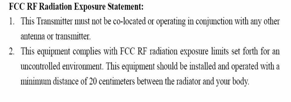
Federal Communication Commission Interference Statement
15.105 Class B
This equipment has been tested and found to comply with the limits for a Class B digital device,
pursuant to Part 15 of the FCC Rules. These limits are designed to provide reasonable protection
against harmful interference in a residential installation. This equipment generates, uses and can
radiate radio frequency energy and, if not installed and used in accordance with the instructions, may
cause harmful interference to radio communications. However, there is no guarantee that
interference will not occur in a particular installation. If this equipment does cause harmful
interference to radio or television reception, which can be determined by turning the equipment off
and on, the user is encouraged to try to correct the interference by one of the following measures:
Reorient or relocate the receiving antenna.
Increase the separation between the equipment and receiver.
Connect the equipment into an outlet on a circuit different from that to which the receiver is
connected.
Consult the dealer or an experienced radio/TV technician for help.
15.21
FCC Caution: Any changes or modifications not expressly approved by the party responsible for
compliance could void the user's authority to operate this equipment.
15.19 Labeling
This device complies with Part 15 of the FCC Rules. Operation is subject to the following two
conditions: (1) This device may not cause harmful interference, and (2) this device must accept any
interference received, including interference that may cause undesired operation.
6
Safety Instructions
1. Read these safety instructions carefully.
2. Keep this User Manual for later reference.
3. Disconnect this equipment from any AC outlet before cleaning. Use a damp cloth. Do not use liquid or
spray detergents for cleaning.
4. For plug-in equipment, the power outlet socket must be located near the equipment and must be easily
accessible.
5. Keep this equipment away from humidity.
6. Put this equipment on a reliable surface during installation. Dropping it or letting it fall may cause
damage.
7. The openings on the enclosure are for air convection. Protect the equipment from overheating. DO
NOT COVER THE OPENINGS.
8. Make sure the voltage of the power source is correct before connecting the equipment to the power
outlet.
9. Position the power cord so that people cannot step on it. Do not place anything over the power cord.
10. All cautions and warnings on the equipment should be noted.
11. If the equipment is not used for a long time, disconnect it from the power source to avoid damage by
transient overvoltage.
12. Never pour any liquid into an opening. This may cause fire or electrical shock.
13. Never open the equipment. For safety reasons, the equipment should be opened only by qualified
service personnel.
14. If one of the following situations arises, get the equipment checked by service personnel:
The power cord or plug is damaged
Liquid has penetrated the equipment.
The equipment has been exposed to moisture.
The equipment does not work well, or you cannot get it to work according to the user's manual.
The equipment has been dropped and damaged.
The equipment has obvious signs of breakage.
15. DO NOT LEAVE THIS EQUIPMENT IN AN ENVIRONMENT WHERE THE STORAGE
TEMPERATURE MAY GO BELOW -20° C (-4° F) OR ABOVE 60° C (140° F). THIS COULD DAMAGE
THE EQUIPMENT. THE EQUIPMENT SHOULD BE IN A CONTROLLED ENVIRONMENT.
16. CAUTION: DANGER OF EXPLOSION IF BATTERY IS INCORRECTLY REPLACED. REPLACE
ONLY WITH THE SAME OR EQUIVALENT TYPE RECOMMENDED BY THE MANUFACTURER,
DISCARD USED BATTERIES ACCORDING TO THE MANUFACTURER'S INSTRUCTIONS.
The sound pressure level at the operator's position according to IEC 704-1:1982 is
no more than 70 dB (A). RESTRICTED ACCESS AREA: The equipment should only be
installed in a Restricted Access Area.
DISCLAIMER:ThissetofinstructionsisgivenaccordingtoIEC704‐1.Advantechdisclaimsall
responsibilityfortheaccuracyofanystatementscontainedherein.
7
PackingList
Before installation, please ensure the following items have been shipped:
1 x DS-565 Unit
1 x English User Manual
1x Accessory box
Chapter1GeneralIntroduction
This chapter gives background information on DS-565 series.
1.1 Introduction
TheDS‐565ispoweredbyIntelCedarview‐MN2600processor‐basedplatformwithDsub15pinVGA
x1andDisplayPortx1.DS‐565mediaplayeristheonlyoneultraslimdevice(166x177x19mm)in
theworldwideandbuildWindows7EmbeddedofOSImagewithsingletouchfunctionthatenables
digitalsignagemanufacturerstodeploysystemsfasteranddevelopmentandimplementation.The
player‐screencommunicationinterfacesupportsdigitalaudio/videosignalsviadisplayport,for
picture‐perfectcontentreproduction.DS‐565alsosupports1xGigaLAN,1xCOMports,4xUSB2.0
givingagreatselectionfordatacommunicationindisplayapplications.Theentiredesignmakes
digitalsignageapplicationsmoreintelligentandconnected.
1.2 ProductFeatures
1.2.1 General
Intel®Cedarview‐MN2600processor‐basedplatform
SupportsHDMIandUSB2.0viaJAE80‐pinconnector
UltraSlimFeatures,easytoinstall
1.2.2 Display
Supportupto1920x1080videoplaybackperformance(subjecttothevideomediaformatand
playbacksoftware)
1.2.3 PowerConsumption
Typical:2.84W
Max.:3.5W
1.3 HardwareSpecifications
CPU: Intel®D2550(1.86GHz)
System Chipset: Intel®NM10Chipset
Graphic chipset: IntegratedgraphicsbuiltinProcessor
BIOS: AMIEFIFlashBIOSviaSPIInterface
System Memory: 1xDDR3204‐pinSODIMMsockets,supportsupto4GBperSO‐DIMM
HDD: Supports1x2.5"SATAHDD(max7mmheight)
8
I/O Interface
1 x VGA
1 x HDMI
4 x USB 2.0 compliant ports
1 audio phone jack for Line-out
1 x COM (RS-232)
1 x MiniPCIe (Internal)
Ethernet Chipset: 1 x Intel 82583V
Speed: 1Gbps(Orange) / 100Mbps (Green) / 10Mbps (Off)
Interface: 1 x RJ-45 jacks with LED
Standard: MDI(copper), IEEE802.3 Ethernet Interface for 1000BASE-T, 100BASE-TX,
and 10BASE-T applications (802.3, 802.3u, and 802.3ab)
Resolution: HDMI up to 1920 x 1080
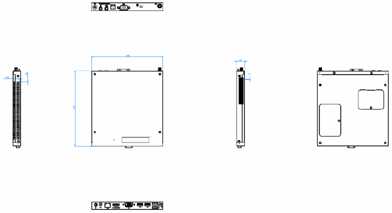
1.4 MechanicalSpecifications
1.4.1 Dimensions
166x177x19mm
Figure.1DS‐565MechanicalDimension(Unit: mm)
1.4.2 Weight
1.0kg(2.2lb.)
9
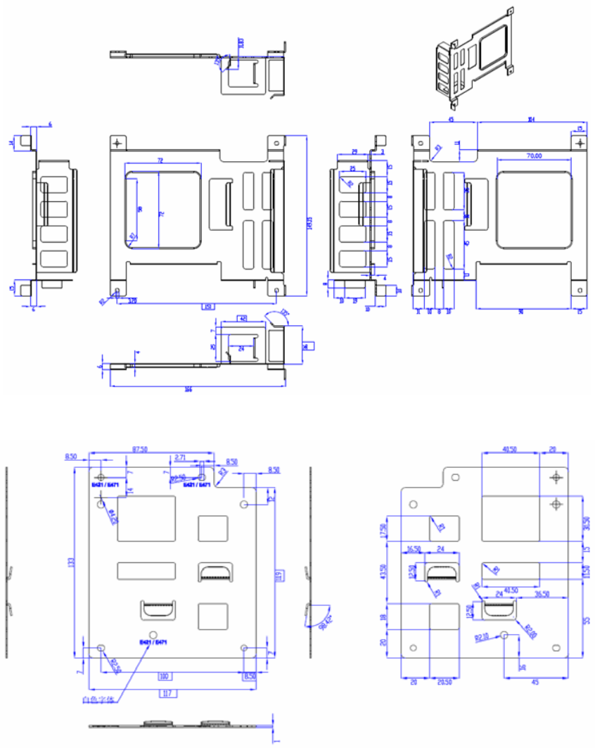
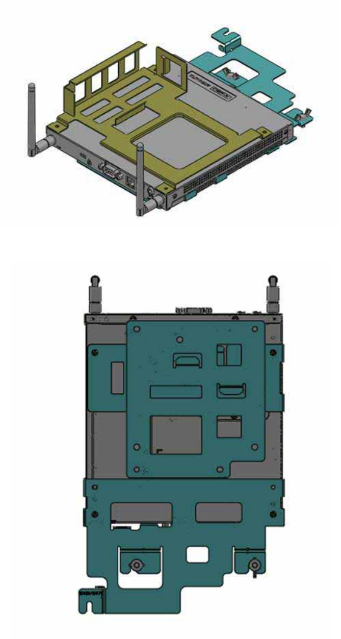
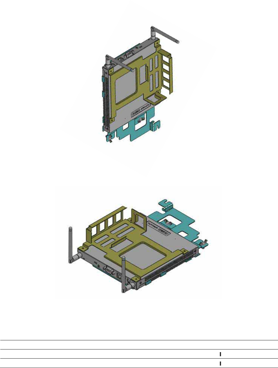
1.5 MountingKit
1.5.1. Dimension
Figure.2AC_TRAY_ANGLE_3
Figure.3ANGLE_BASE
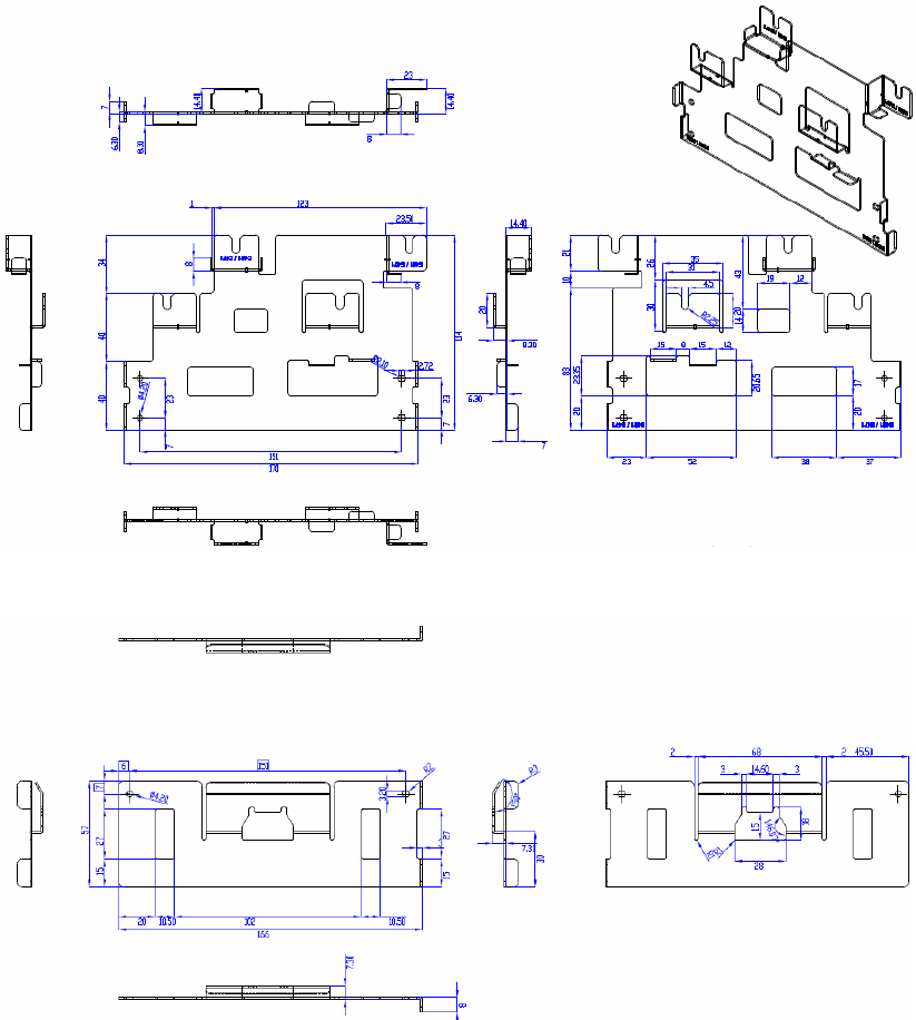
10
Figure.4ANGLE_CB
Figure.5ANGLE_CT
**Warning! Use suitable mounting apparatus to avoid risk of injury.
11
1.5.2. Installatiionwithbrackets
Figure.6SystemwithBrackets(topview)
Figure.7Systemwithbrackets(bottomview)
**Note! This pair of wallmount bracket is designed for side of chassis and bottom
side. Reverse installation is not permitted.
12
1.5.3. DirectionofSystemswithbracket
(1) Directionmethod1:Upright
(2) Directionmethod2:Flatways
1.6 PowerRequirements
1.6.1 SystemPower
19VDC‐in
ModelnameOutputratedTma(degreeC)
FSP065‐RAB19VDC,3.42A40 (+‐5%)
ADP_65JHABCD19VDC,3.42A40 (+‐5%)
**CAUTION:Providedwitheachunit."ThisproductisintendedtobesuppliedbyanULcertifiedpower
supply,outputrated19Vdc,3.31Aminimum,Tma=40degreeC."orequivalentstatementprovidedin
operatingmanual,ifpowerunitisnotprovided.
13
1.6.2 RTCBattery
1xPHsocket,underheightlimit
**CAUTION:RISKOFEXPLOSIONIFBATTERYISREPLACEDBYANINCORRECTTYPE.
DISPOSEOFUSEDBATTERIESACCORDINGTOTHEINSTRUCTIONS
1.7 EnvironmentalSpecifications
1.7.1 OperatingTemperature
‐5°C~50°C(23°F~122°F)
1.7.2 RelativeHumidity
95%@40°C(non‐condensing)
1.7.3 StorageTemperature
40℃;60℃(‐4°F;140°F)
1.7.4 VibrationLoadingDuringOperation
5‐500Hz,PSD0.0005G²/Hz,0.5Grms,3axes,1hr/peraxis
1.7.5 Safety
UL,TUV,CB,C‐Tick,RCM,BSMI,CELVD,NOM,EAC,SMark,BSMI,CCC
1.7.6 EMC
CE,FCCClassB,VCCI,BSMI,C‐Tick
1.7.7 RF
FCC,R&TTE,TELEC,NCC,FCCID,A‐Tick
14
Chapter2HardwareInstallation
ThischapterintroducesexternalI/OandtheinstallationofDS‐565Hardware.
2.1 DS‐563I/OConnectors
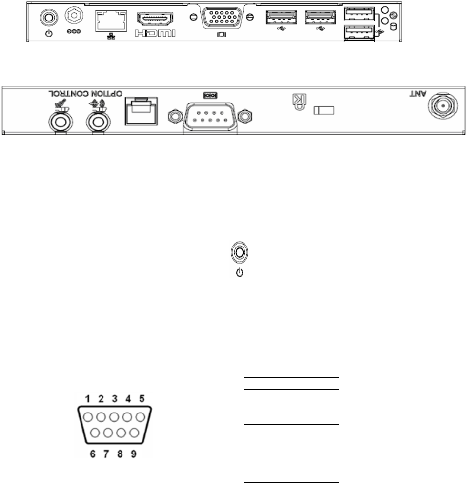
2.1.1 FrontI/O
2.1.2 RearI/O
2.2 DS‐563ExternalI/OConnectors
2.2.1 PowerON/OFFButton
DS‐565hasapowerON/OFFbuttononthefrontside.PushthisbuttontoturnthesystemON
andOFF.Italsosupportsa5seconddelaysoftpoweroff.
Figure.8PowerON/OFFButton
2.2.2 COMConnector
DS‐565providesoneD‐sub9‐pinconnectorsserialcommunicationinterfaceport.Theports
supportRS‐232modecommunications.
Figure.9COMConnector
Table.1COMConnectorPinAssignments
Pin Signal Name
1 DCD
2 RxD
3 TxD
4 DTR
5 GND
6 DSR
7 RTS
8 CTS
9 RI
15
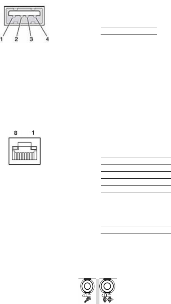
2.2.3 USB1~4Connectors
DS‐565providesfourUSBinterfaceconnectors,whichgivescompletePlug&Playandhot
swappingcapabilityforupto127externaldevices.TheUSBinterfaceiscompliantwithUSB
UHCI,Rev.2.0.TheUSBinterfacesupportsPlugandPlay,whichenablesyoutoconnector
disconnectadevicewithoutturningoffthesystem.
Figure.10USB1~4Connectors
Table.2USB1~4PortPinAssignments
Pin Signal Name
1 VCC
2 USB Data-
3 USB Data+
4 GND
2.2.4 EthernetConnector(LAN)
DS‐565providesoneRJ‐45LANinterfaceconnector,fullycompliantwithIEEE802.3u
10/100/1000Base‐TCSMA/CDstandards.TheEthernetportprovidesastandardRJ‐45jack
connectorwithLEDindicatorstoshowitsActive/Linkstatusandspeedstatus.
Figure.11EthernetConnector
Table.3LANConnectorPinAssignments
Pin Signal Name
1 MDI0+
2 MDI0-
3 MDI1+
4 MDI1-
5 GND
6 GND
7 MDI2+
8 MDI2-
9 MDI3+
10 MDI3-
11 VCC
12 ACT
13 +V3.3 & Link1000#
14 +V3.3 & Link100#
2.2.5 AudioConnector
Line in/ Out: Stereospeakers,earphoneorfrontsurroundspeakerscanbeconnectedtothe
line–in/line‐outjack.
Figure.12Line‐in/Line‐out

16
2.2.6 PowerSwitch(OptionalContrl):RJ11
RJ‐11onlyusesforPowerswitchbetweendeviceandpanel,notfortelecommunicate
function.
**CAUTION:EXCEPTPOWERSWITCHFUNCTION,CANCAUSEANYDEVICEBUREDUP,FIRE,AND
DANGEROUSRESULTS.
2.2.7 HDMI
Anintegrated,19‐pinreceptacleconnectorHDMITypeAInterfaceisprovided.TheHDMIlink
supportsresolutionsupto1920x1080(HDMI&VGA).
Figure.13HDMIConnector
Table.4DisplayPortPinout
Pin SignalName
1TMDSData2+
2TMDSData2shield
3TMDSData2‐
4TMDSData1+
5TMDSData1shield
6TMDSData1‐
7TMDSData0+
8TMDSData0shield
9TTMDSData0‐
10 TMDSClock+
11 TMDSClockshield
12 TMDSClock‐
13 CEC
14 Reserved
15 SCL
16 SDA
17 DDC/CECGround
18 +5V
19 HotPlugDetect
17
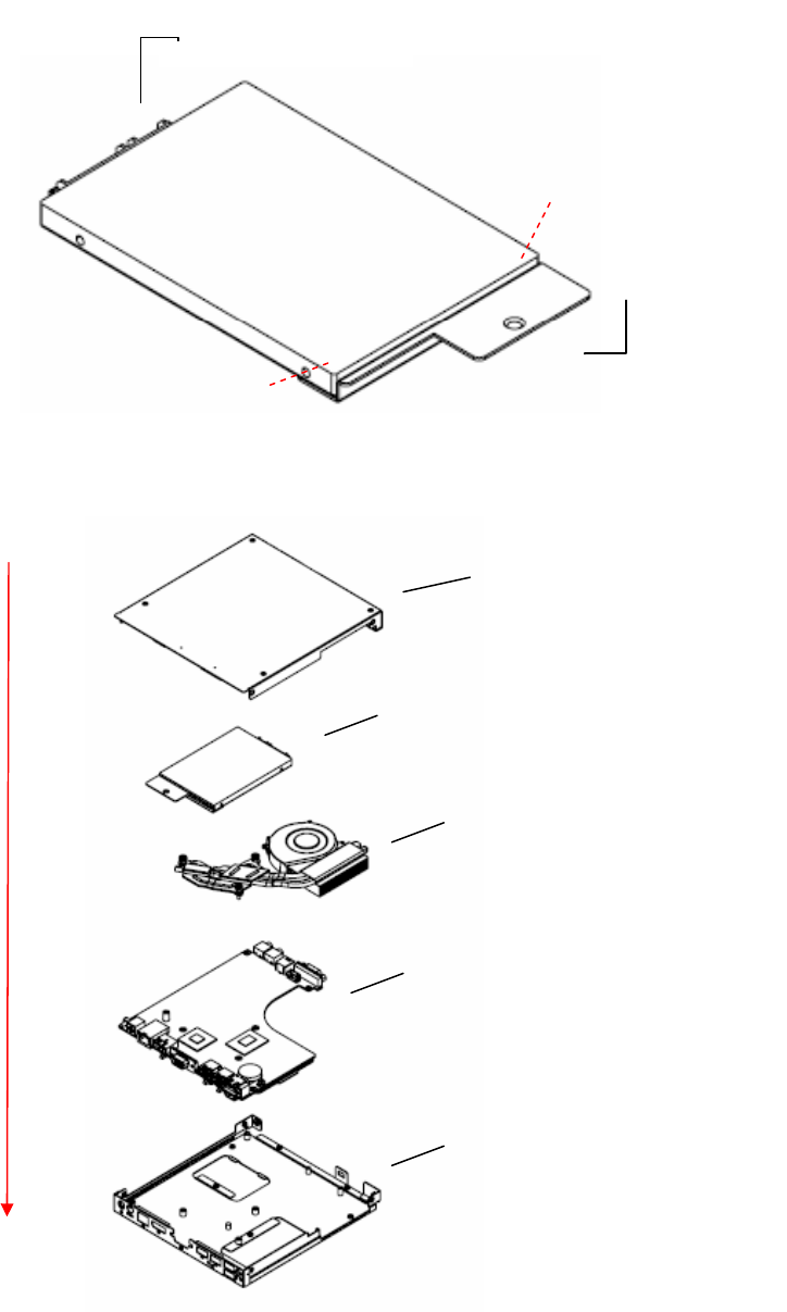
2.3 HardwareInstallation
2.3.1 HDDInstallation
(1) ToassemblyaHDDmodule,secureHDDtoHDDbracketwith2screws.
(2) InstallaHDDmoduleintoDS‐565,thensecureitwithascrew.
Figure.14HDDInstallation
Figure.15SystemInstallation
SATAconnector
HDDbracket
Screw1
Screw2
HDDModule
Topcover
FANModule
M/B
Bottomcover
Installeddirection
18
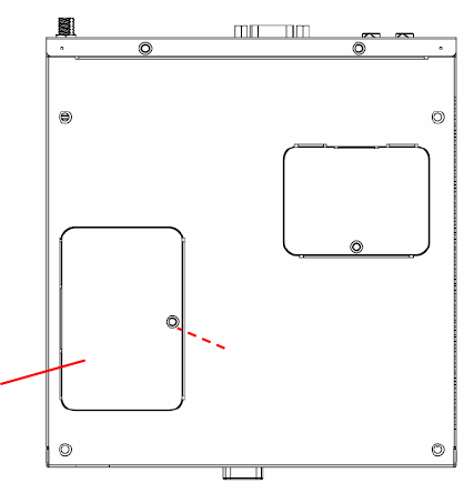
2.3.2 MemoryInstallation
(1) Beeasytoinstall/removememoryonbottomcover.
(2) Removememorycoverandreplacememoryinside.
(3) Installthememorycover,thensecurewithscrew.
Figure.16MemoryInstallation
Memorycover
Screw
19
Chapter3BIOSSettings
This chapter introduces how to set BIOS configuration data.
3.1 BIOSIntroduction
AMIBIOShasbeenintegratedintomanymotherboardsforovertwodecades.WiththeAMIBIOS
Setupprogram,youcanmodifyBIOSsettingsandcontrolvarioussystemfeatures.Thischapter
describesthebasicnavigationoftheDS‐565seriesBIOSsetupscreens.
AMIBIOS’sROMhasabuilt‐insetupprogramthatallowsuserstomodifythebasicsystem
configuration.Thisinformationisstoredinbattery‐backedCMOSsoitretainsthesetupinformation
whenthepoweristurnedoff.
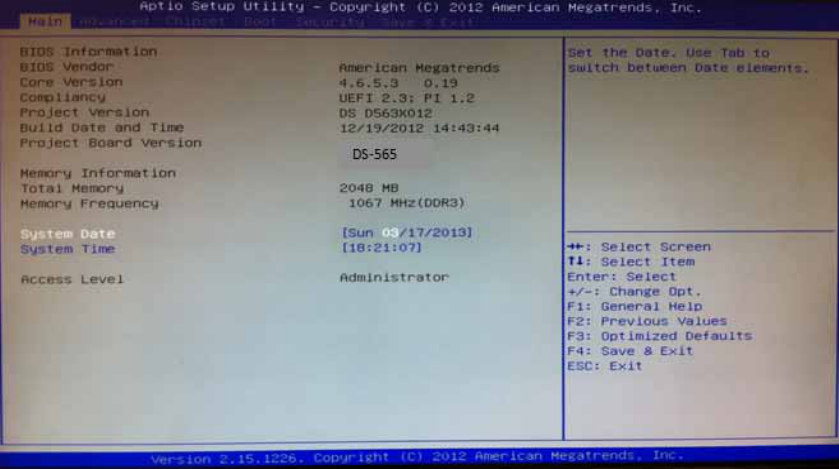
3.2 MainSetup
WhenyoufirstentertheBIOSSetupUtility,youwillentertheMainsetupscreen.Youcanalways
returntotheMainsetupscreenbyselectingtheMaintab.
TheMainBIOSsetupscreenhastwomainframes.Theleftframedisplaysalltheoptionsthatcanbe
configured.Optionsinbluecanbeconfigured,andgrayed‐outoptionscannotbeconfiguredinstead.
Therightframedisplaysthekeylegend.
Thekeylegendinthetopisanareareservedforatextmessage.Whenanoptionisselectedinthe
leftframe,itishighlightedinwhite.Oftenatextmessagewillaccompanyit.
3.2.1 SystemTime/SystemDate
Usethisoptiontochangethesystemtimeanddate.HighlightSystemTimeorSystemDate
usingthe<Arrow>keys.Enternewvaluesthroughthekeyboard.Pressthe<Tab>keyorthe
<Arrow>keystomovebetweenfields.ThedatemustbeenteredinMM/DD/YYformat.The
timemustbeenteredinHH:MM:SSformat.
Figure.17MainSetupScreen
20
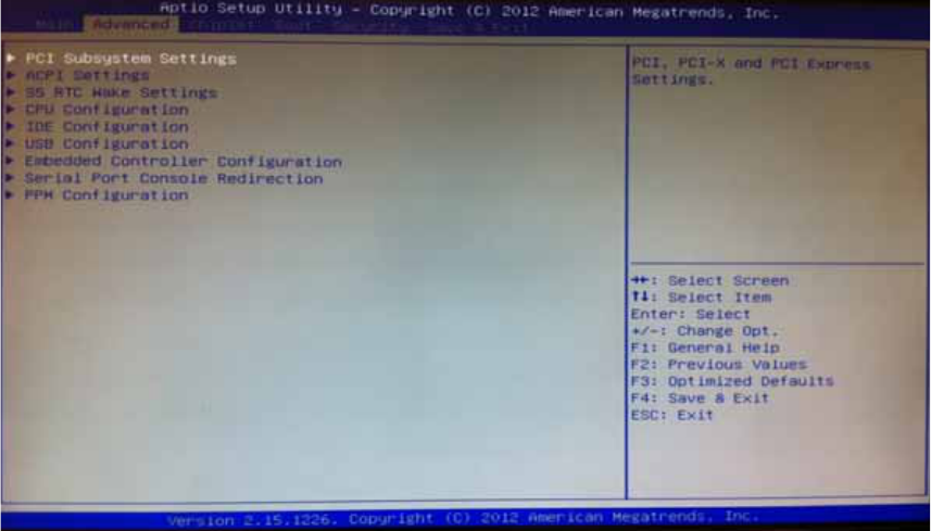
3.2.2 AdvancedBIOSFeaturesSetup
SelecttheAdvancedtabfromtheDS‐565setupscreentoentertheAdvancedBIOSSetup
screen.Youcanselectanyoftheitemsintheleftframeofthescreen,suchasCPU
configuration,togotothesubmenuforthatitem.YoucandisplayanAdvancedBIOSSetup
optionbyhighlightingitusingthe<Arrow>keys.AllAdvancedBIOSSetupoptionsare
describedinthissection.TheAdvancedBIOSSetupscreensareshownbelow.Thesubmenus
aredescribedonthefollowingpages.
Figure.18AdvancedBIOSFeaturesSetupScreen
ACPI Settings: Thissectionallowsyoutocontrolhardwaremonitoringandpower
management
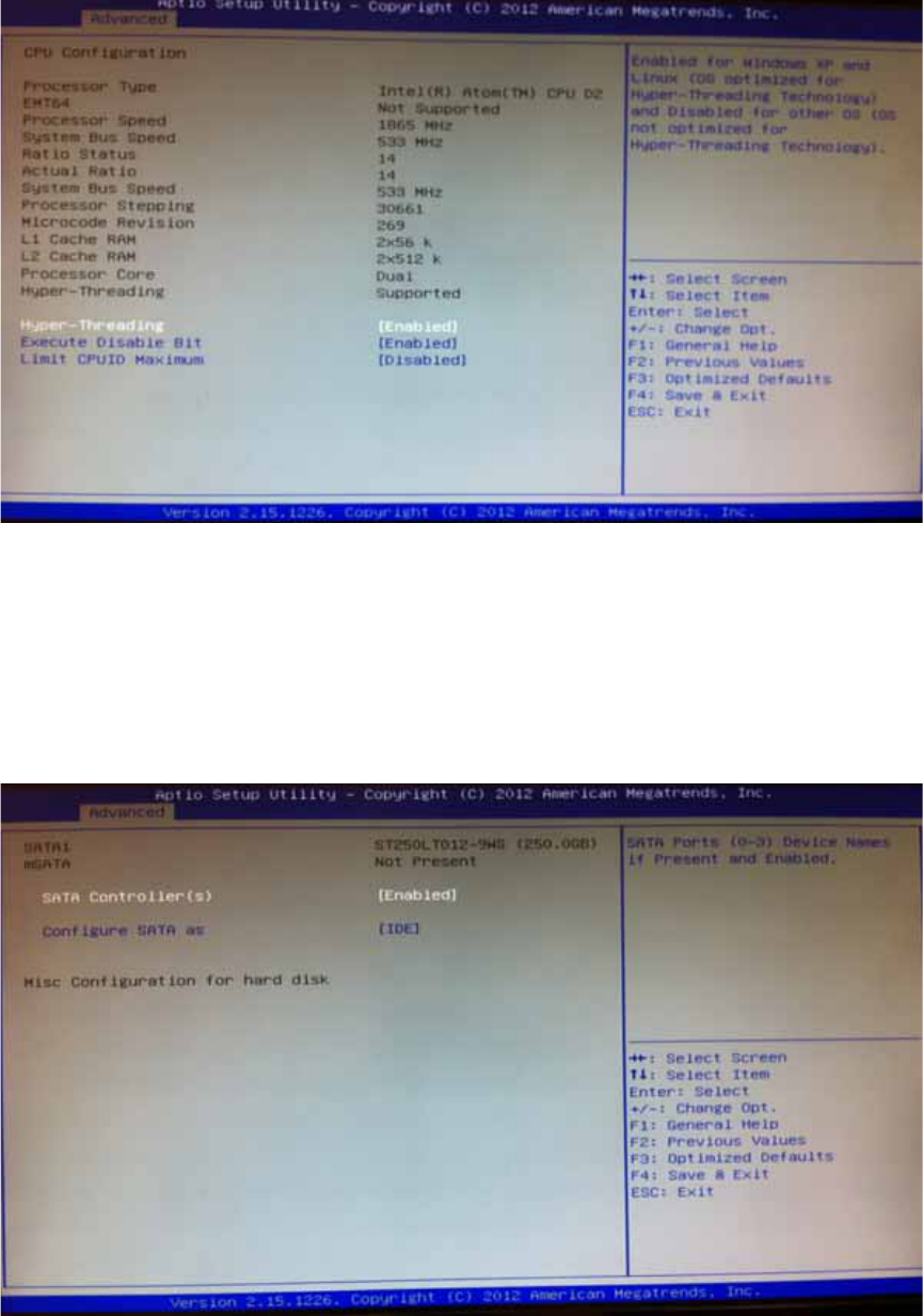
CPU Configuration:
Hyper‐threading:EnabledforWindowsXPandLinux(OSoptimizedforHyper‐Threading
Technology)andDisabledforotherOS(OSnotoptimizedforHyper‐Threading
Technology).Whendisabled,onlyonethreadperenabled‐coreisenabled.
ActiveProcessorCores:Numberofcorestobeenabledineachprocessorpackage.
LimitCPUIDMaximum:DisabledforWindowsXP.
Execute Disable Bit:
Itcanpreventcertainclassesofmaliciousbufferoverflowattackswhencombinedwitha
supportingOS(WindowsServer2003Sp1,WindowsXPSP2,SuSELinux9.2RedHatEnterprise
3Update3.).
IntelVirtualizationTechnology:Whenenabled,aVMMcanutilizetheadditional
hardwarecapabilitiesprovidedbyVanderpoolTechnology.
HardwarePrefetcher:Toturnon/offtheMidLevelCache(L2)streamerprefetcher.
AdjacentCacheLinePrefetch:Toturnon/offprefetchingofadjacentcachelines
21
Figure.19CPUSettingpage
SATA Configuration:
ThissectionallowsyoutosetupSATAdevicesconfiguration.
SATAController(s):EnableordisableSATADevice.
SATAModeSelection:DetermineshowSATAcontroller(s)operate.Thechoice:IDE,AHCI,
RAID
Figure.20SATASettingpage
PCH-FW Configuration: ConfigurationManagementEngineTechnologyParameters.
AMT Configuration:ConfigurationActiveManagementTechnologyparameters.
IntelAMT:Enable/DisableIntel(R)ActiveManagementTechnologyBIOSExtension.
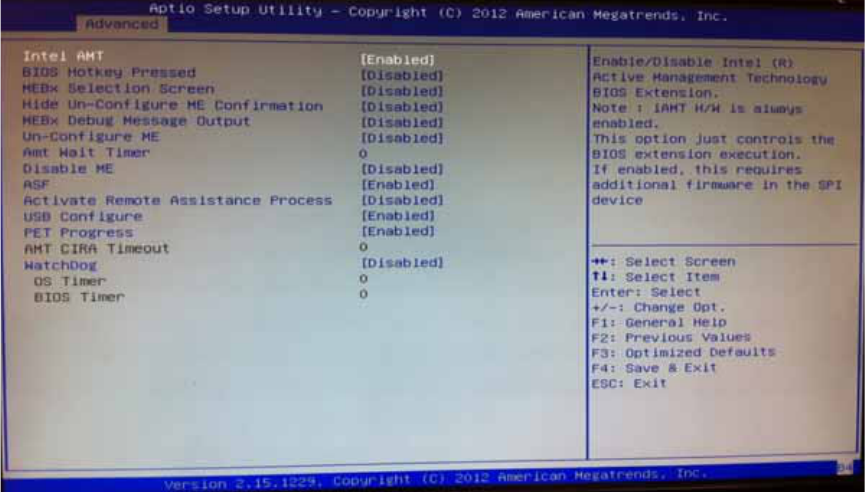
22
Note:iAMTH/Wisalwaysenabled.ThisoptionjustcontrolstheBIOSextension.If
enabled,thisrequiresadditionalfirmwareintheSPIdevice.
BIOSHotkeyPressed:OEMFLagBit1:Enable/DisableBIOShotkeypress.
MEBxSelectionScreen:OEMFLagBit2:Enable/DisableMEBxselectionscreen.
HideUn‐ConfigureMEConfirmation:OEMFLagBit6:HideUn‐ConfigureMEwithout
passwordConfirmationPrompt.
MEBxDebugMessageOutput:OEMFLagBit14:EnableMEBxdebugmessageOutput.
Un‐ConfigureME:OEMFLagBit15:Un‐ConfigureMEwithoutpassword.
AmtWaitTimer:SettimertowaitbeforesendingASF_GET_BOOT_OPTIONS.
ASF:Enable/DisableAlertSpecificationFormat
ActivateRemoteAssistanceProcess:TriggerCIRAboot.
USBConfigure:Enable/DisableUSBConfigurefunction.
PETProgress:UsercanEnable/DisablePETEventsprogresstoreceivePETeventsornot.
WatchDog:Enable/DisableWatchDogTimer.
Figure.21AMTConfigurationsetting
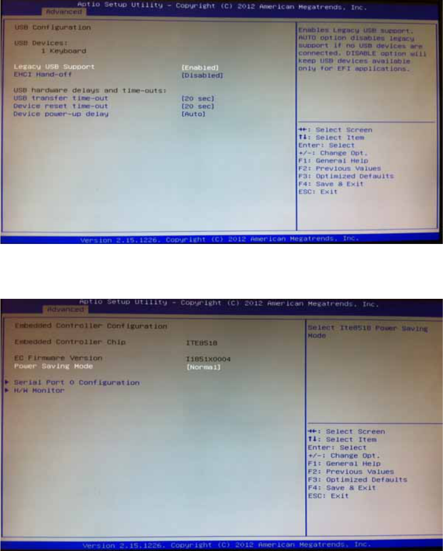
USB Configuration: USBConfigurationParameters.
LegacyUSBSupport:EnableLegacyUSBsupport.AUTOoptiondisableslegacysupportif
noUSBdevicesareconnected.DISABLEoptionwillkeepUSBdevicesavailableonlyforEFI
applications
EHCIHand‐off:Thisisaworkaroundfor0SeswithoutEHCIhand‐offsupport.TheEHCI
ownershipchangeshouldbeclaimedbyEHCIdriver.
USBtransfertime‐out:Thetime‐outvalueforControl,Bulk,andInterrupttransfers.The
choice:1sec,5sec,10sec,20sec
Deviceresettime‐out:USBmassstoragedeviceStartUnitCommandtime‐out.Thechoice:
10sec,20sec,30sec,40sec
Devicepower‐updelay:USBmassstoragedeviceStartUnitCommandtime‐out.
23
Figure.22USBConfigurationsetting
Serial Port 0 Configuration: SetParametersofSerialport0(COM)
Figure.23SerialPort0Configurationsetting
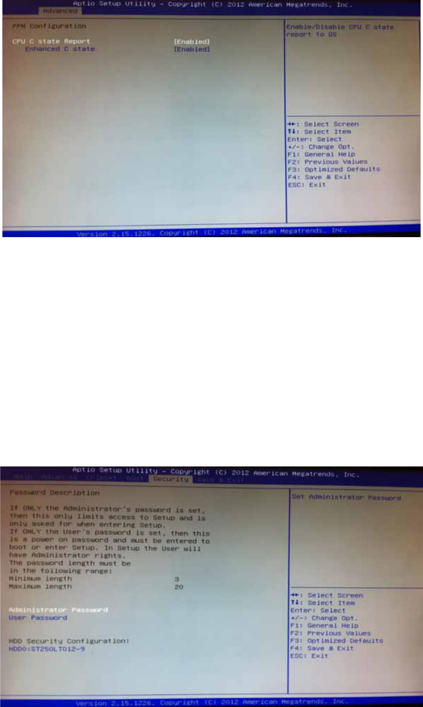
CPU PPM Configuration: CPUPPMConfigurationParameters
EIST:Enable/DisableIntelSpeedStep
TurboMode:TurboMode
CPUC3Report:Enable/DisableCPUC3(ACPIC2)reporttoOS
24
Figure.24CPUPPMConfigurationsetting
3.2.3 ChipsetBIOSFeatureSetup
SelecttheChipsettabfromtheDS‐565setupscreentoentertheChipsetBIOSSetupscreen.
Userscanselectanyitemintheleftframeofthescreen,suchasPCH‐IOConfigurationand
SystemAgentConfiguration.
3.2.4 SecurityBIOSFeatureSetup
SelecttheBOOTtabfromthesetupscreentoentertheSecurityBIOSSetupscreen.
AdministratorPassword:SetupAdministratorPassword.Whenset,limitsaccesstoBIOS
Setup.
UserPassword:SetUserPassword.Whenset,limitsmachinebootandaccesstoBIOS
Setup.
25
Figure.25SecurityBIOS
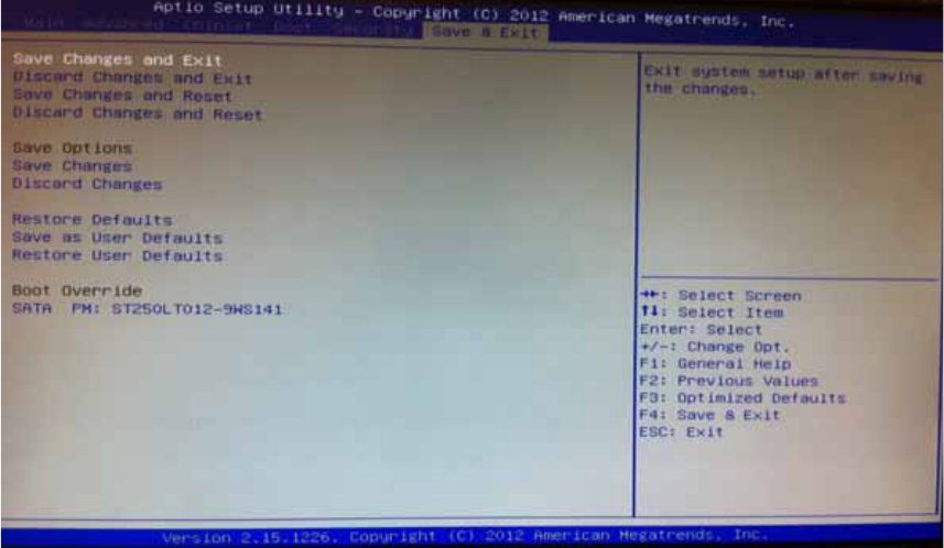
3.2.5 Save&ExitBIOSFeatureSetup
SelecttheBOOTtabfromthesetupscreentoenterthesaveBIOSSetupscreen.
SaveChangesandExit:Exitsystemsetupaftersavingthechanges.
DiscardChangesandExit:Exitsystemsetupwithoutsavinganychanges.
SaveChangesandReset:Resetthesystemaftersavingthechanges.
DiscardChangesandReset:Resetsystemsetupwithoutsavinganychanges.
SaveChanges:SaveChangesdonesofartoanyofthesetupoptions.
DiscardChanges:DiscardChangesdonesofartoanyofthesetupoptions.
RestoreDefaults:Restore/LoadDefaultsvaluesforallthesetupoptions.
SaveasUserDefaults:SavethechangesdonesofarasUserDefaults.
RestoreUserDefaults:RestoretheUserDefaultstoallthesetupoptions.
Figure.26Save&ExitBIOSFeatureSetup
26