Advantech Co DVS-350 Embedded/Mobile Digital Video System User Manual
Advantech Co Ltd Embedded/Mobile Digital Video System Users Manual
UserManual.wiki
>
Advantech Co
>
DVS 350 User Manual
Users Manual
Navigation menu
Upload a User Manual
Namespaces
Wiki Guide
HTML
PDF
Info
Views
User Manual
Discussion / Help
Navigation
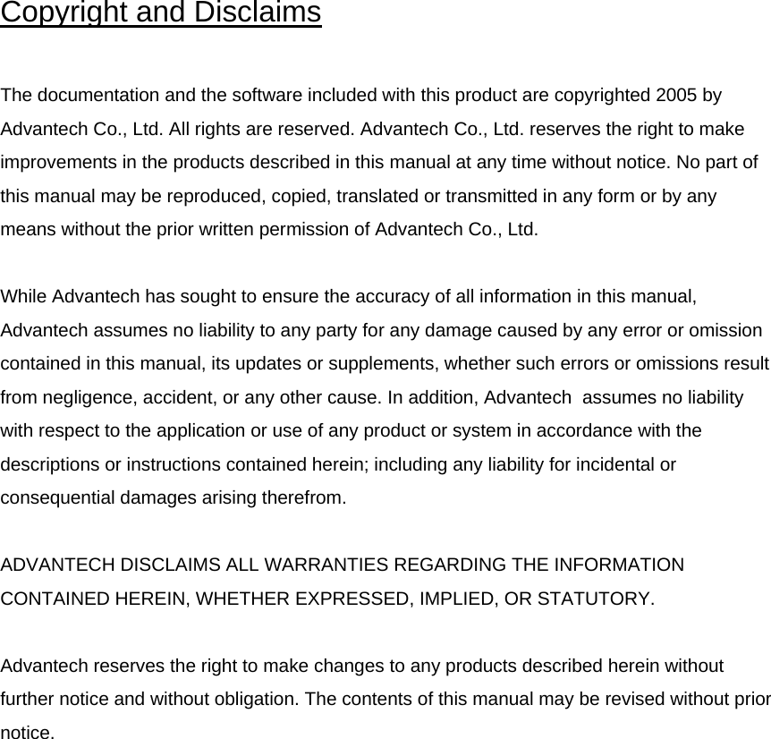
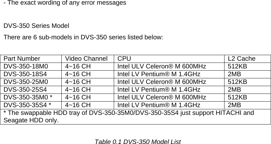

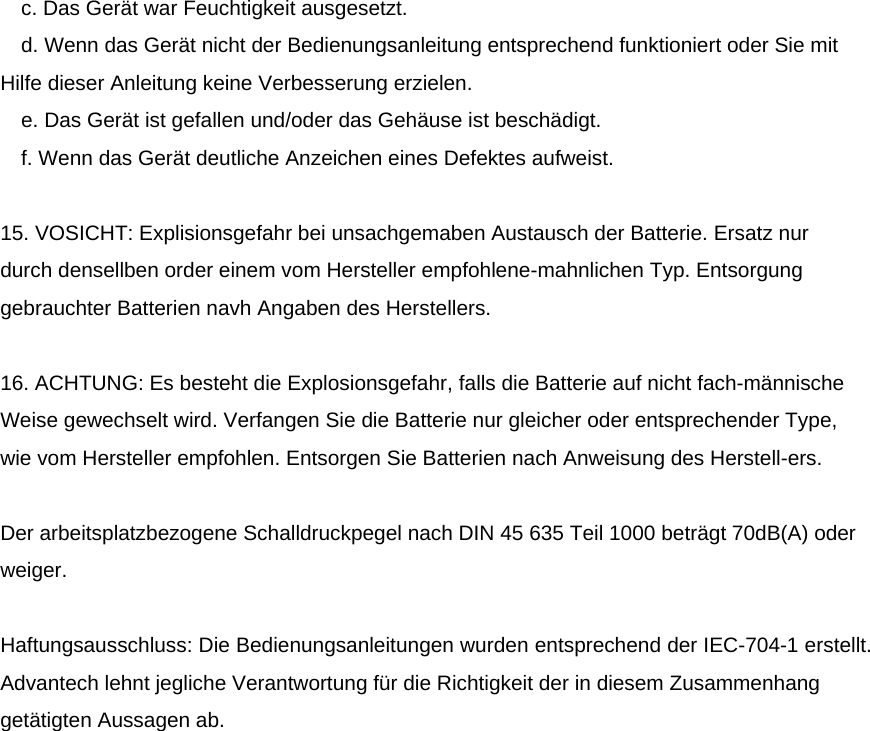

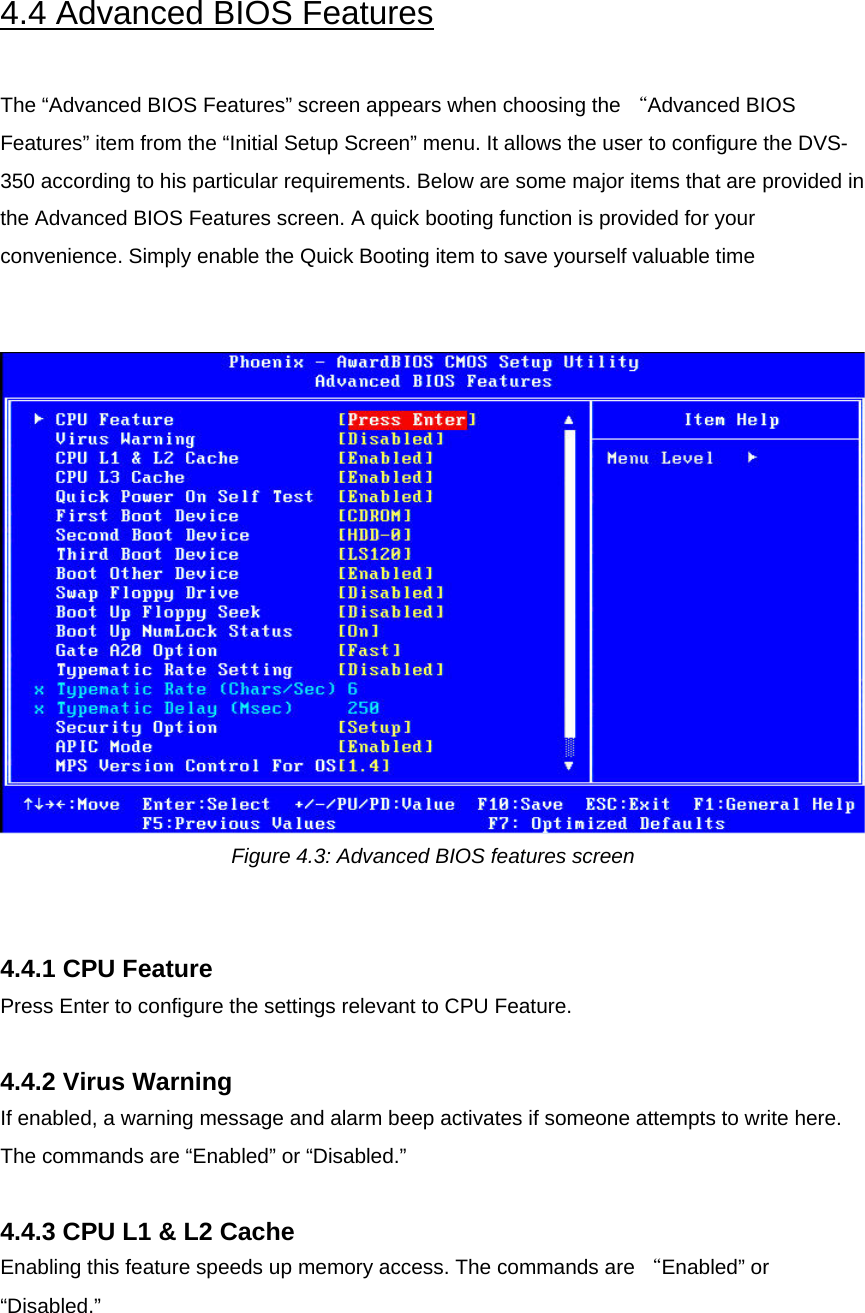
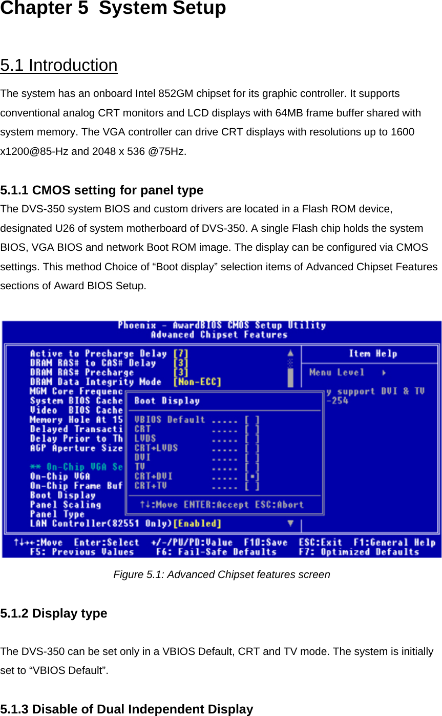
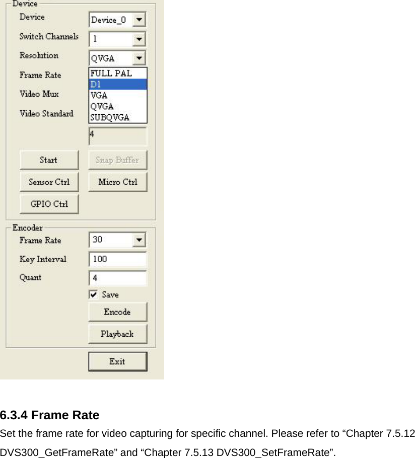
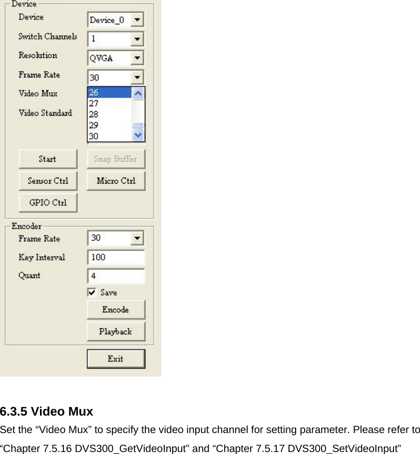
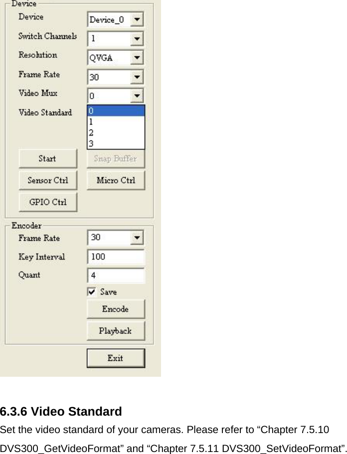
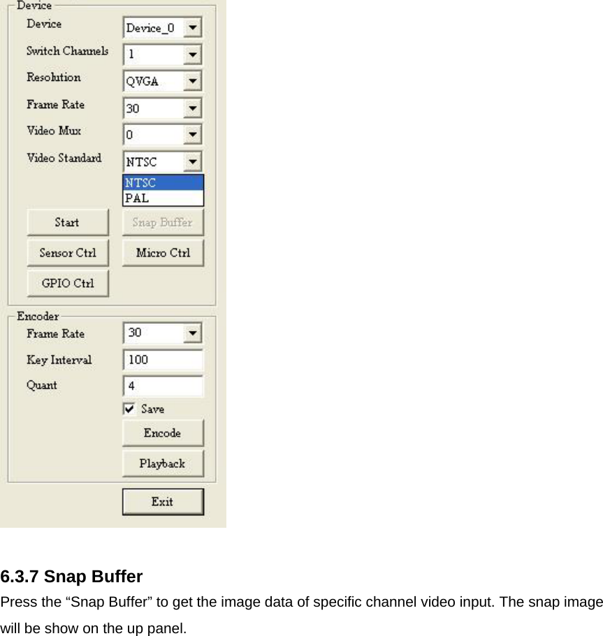
![4.7.13 PCI PIRQ [A-D]# When Enabled, the system will resume from suspend mode if interrupt occurs. The choice: Enabled, Disabled. 4.8 PnP/PCI Configurations 4.8.1 PnP OS Installed Select “Yes” if you are using a plug and play capable operating system. Select No if you need the BIOS to configure non-boot device Figure 4.7: PnP/PCI configurations screen 4.8.2 Reset Configuration Data Default is Disable. Select Enable to reset Extended System Configuration Data (ESCD) if you have installed a new add-on and system configuration has caused such a conflict that OS cannot boot. 4.8.3 Resources controlled by: The commands here are “Auto” or “Manual.” Choosing “manual” requires you to choose resources from each following sub-menu. “Auto” automatically configures all of the boot and Plug and Play devices but you must be using Windows 95 or above.](https://usermanual.wiki/Advantech-Co/DVS-350/User-Guide-690280-Page-52.png)