Advantech Co EKI1362 Serial Device Server User Manual
Advantech Co Ltd Serial Device Server
UserManual.wiki
>
Advantech Co
>
EKI1362 User Manual
User Manual
Navigation menu
Upload a User Manual
Namespaces
Wiki Guide
HTML
PDF
Info
Views
User Manual
Discussion / Help
Navigation


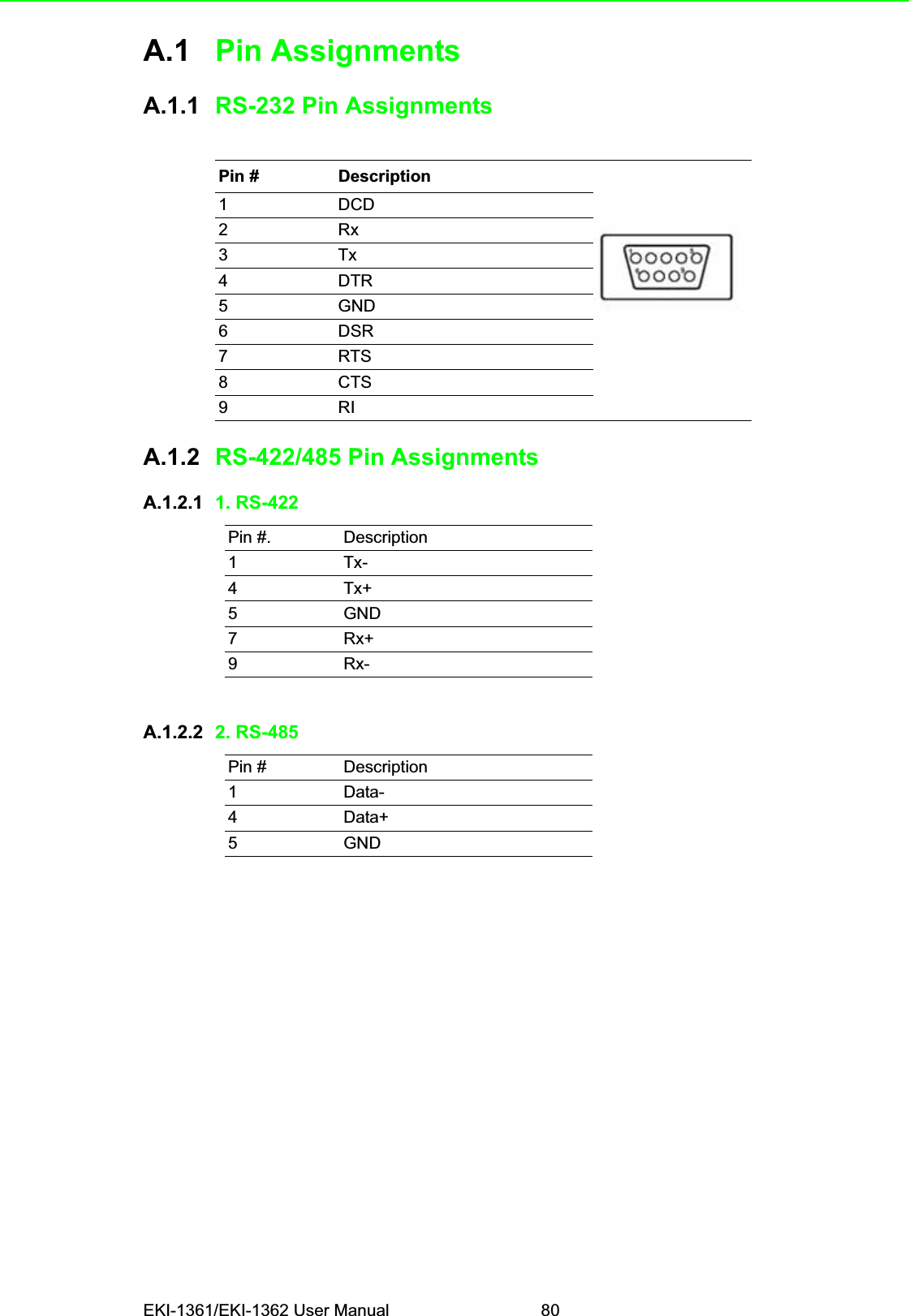
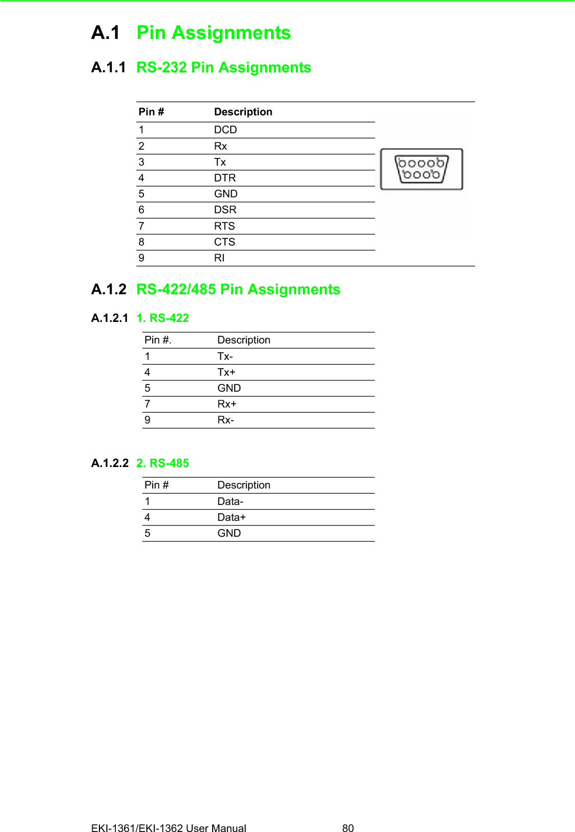
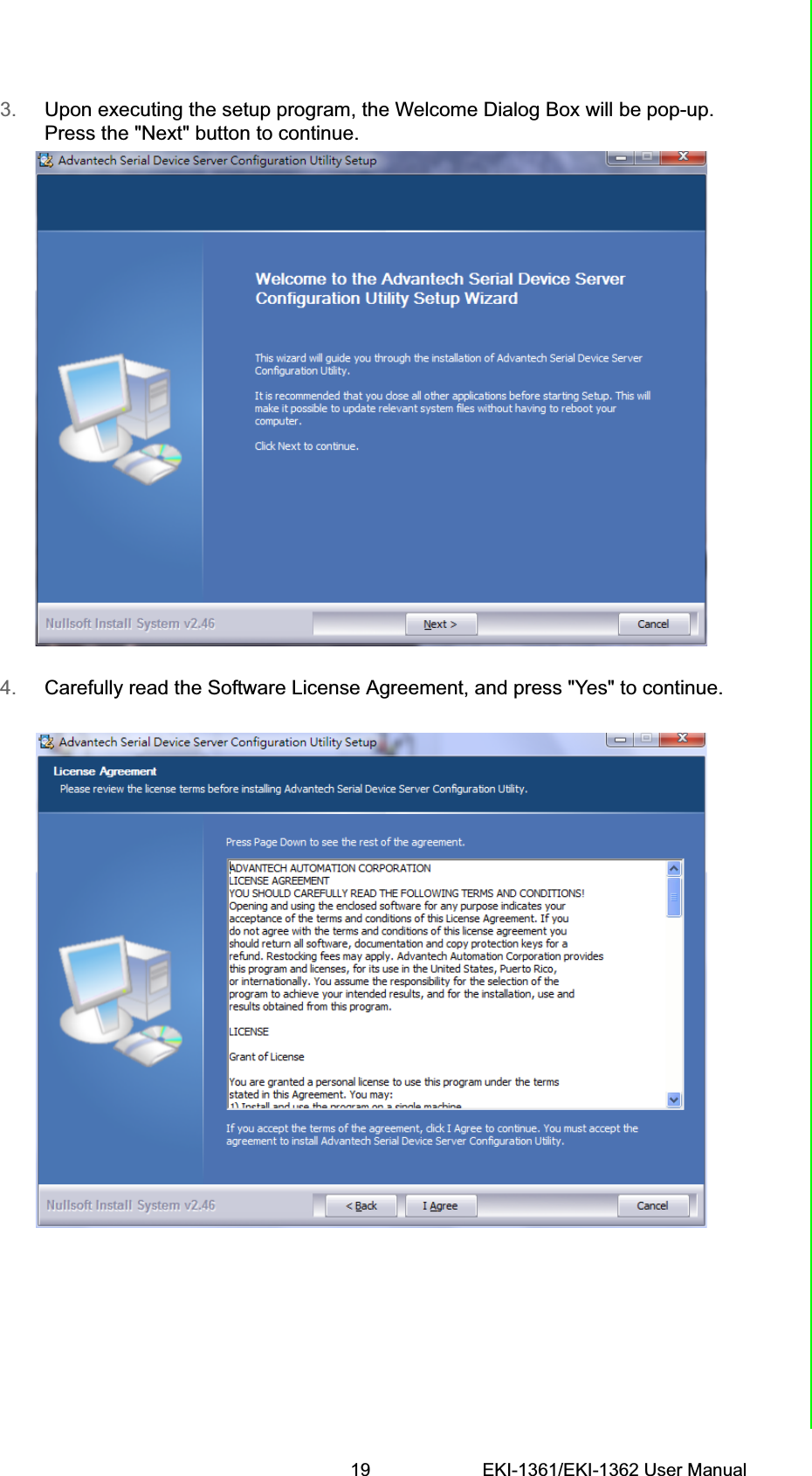
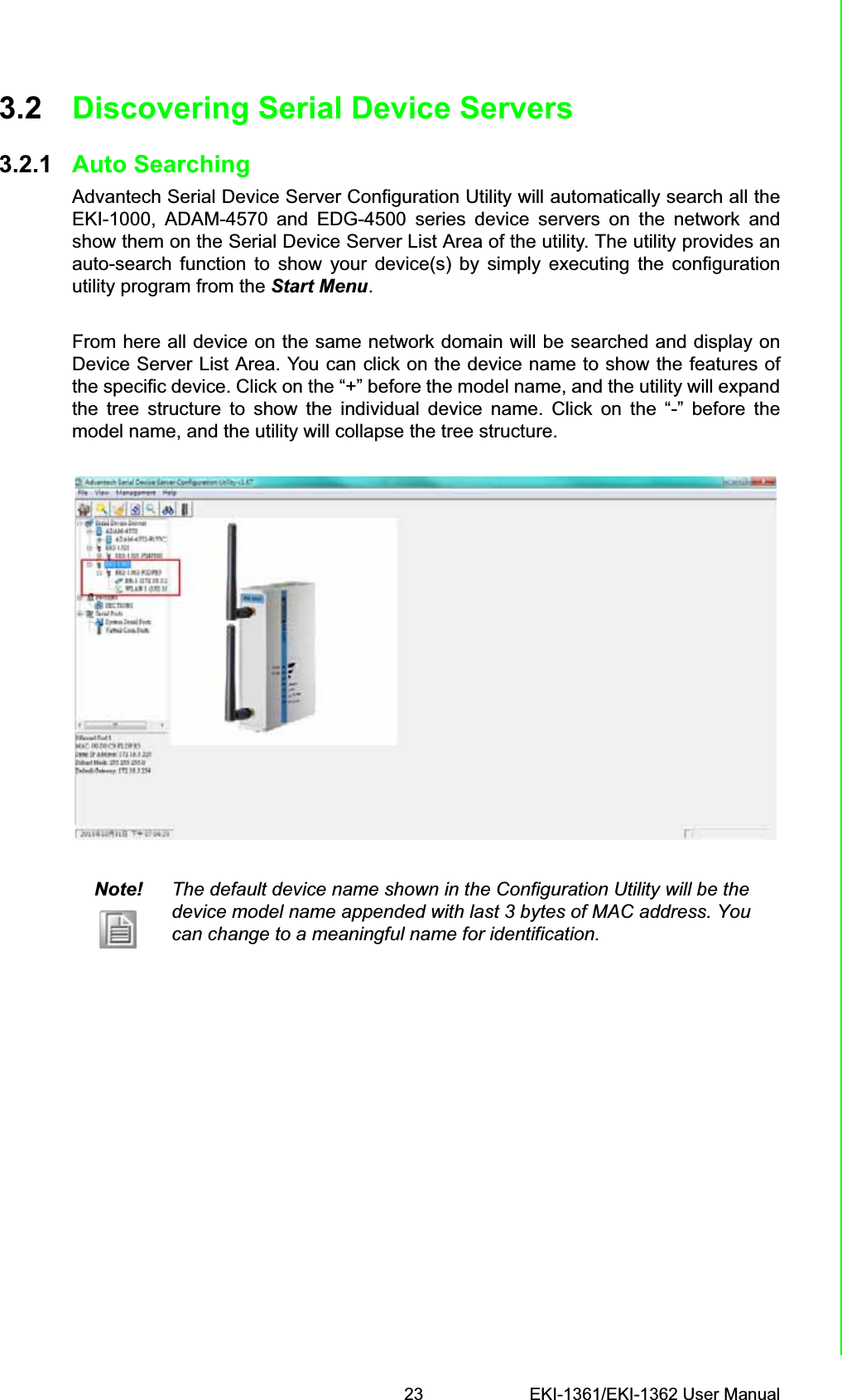
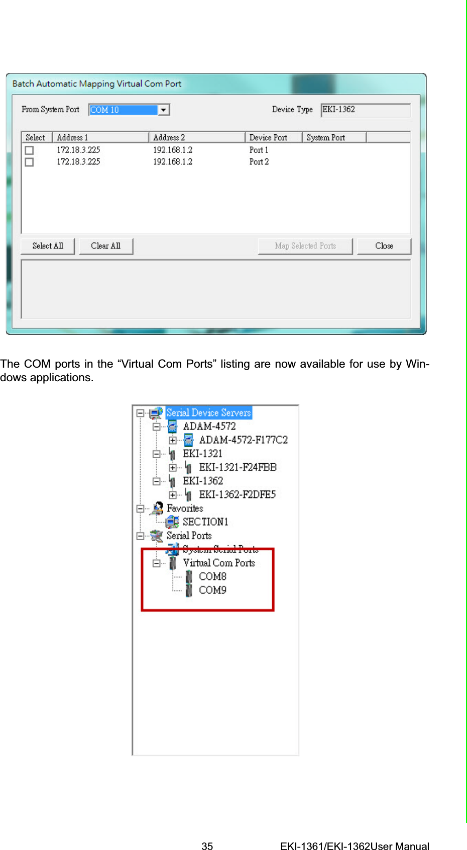
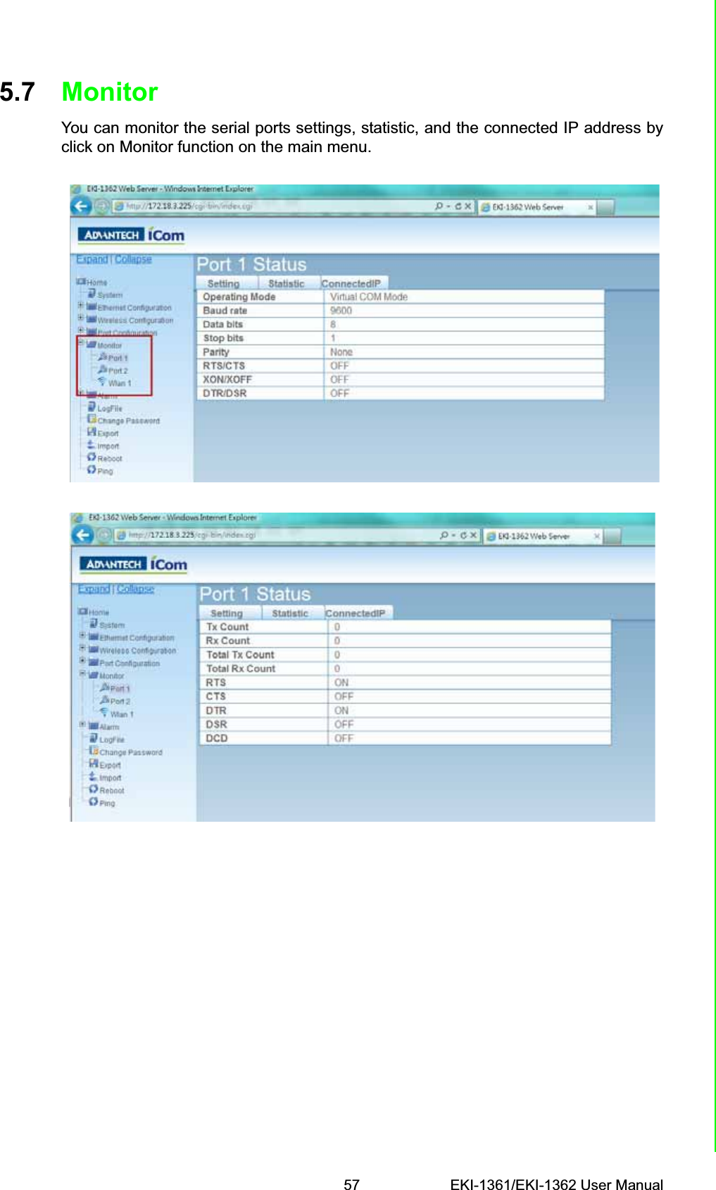
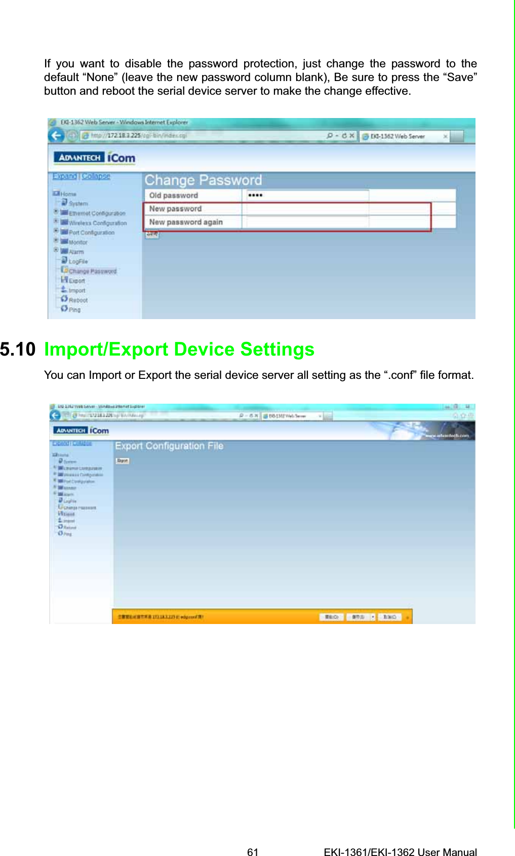
![EKI-1361/EKI-1362 User Manual 182.3.5 Serial ConnectionEKI-1361/EKI-1362 provides 1 or 2 serial ports with DB9 (male) connectors. RS-232/422/485 pin assignments as below:2.4 Installing the Configuration UtilityThe following section will show you how to install the Advantech serial device serverconfiguration utility, a tool to set up and monitor the EKI serial device servers.1. Insert the Advantech industrial communication IEDG series driver utility CD into the CD-ROM drive (e.g. E:\) on the host PC.2. Use Windows explorer or the Windows Run command to execute the setup pro-gram, the path for the setup program on the CD-ROM should be: E:\Util-ity&Driver\SerialDeviceServerConfigurationUtility\Serial_Device_Server_Configuration_Utility_[Version]_Release_[date].exeTable 2.2: EKI-152X series Serial Pin AssignmentsPin 1 2 3 4 5 6 7 8 9RS-232 DCD RX TX DTR GND DSR RTS CTS RIRS-422 TX- - - TX+ GND - RX+ - RX-RS-485 DATA- - - DATA+ GND - - - -Note! Be sure the Microsoft .NET Framework on your host PC is greater than version 2.0.](https://usermanual.wiki/Advantech-Co/EKI1362/User-Guide-2210809-Page-26.png)
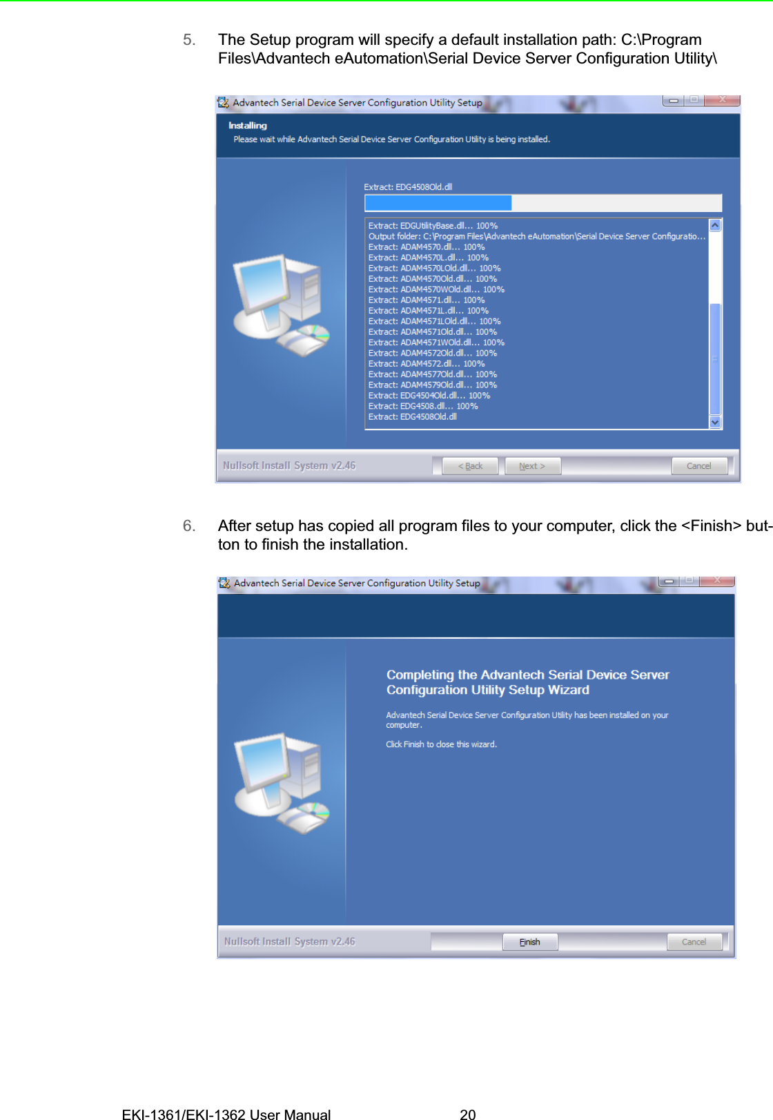
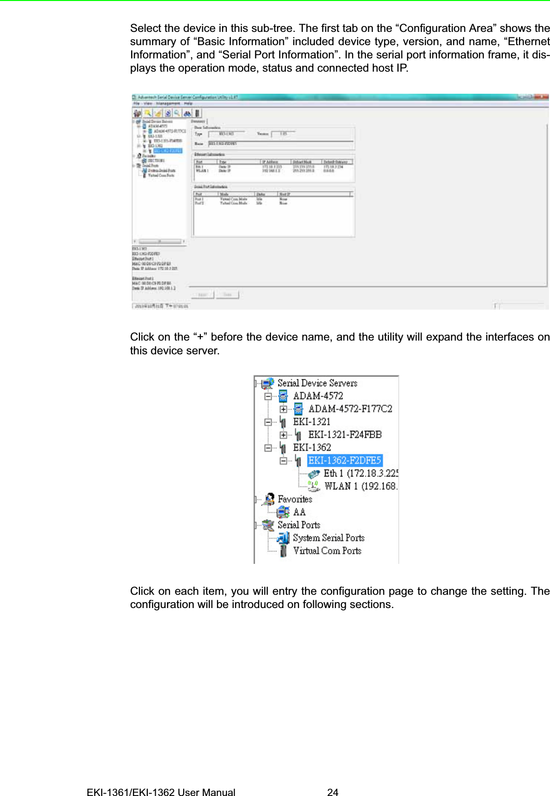
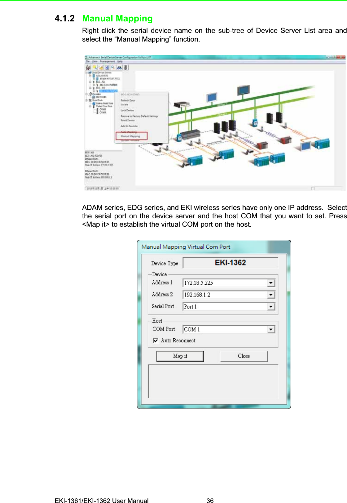


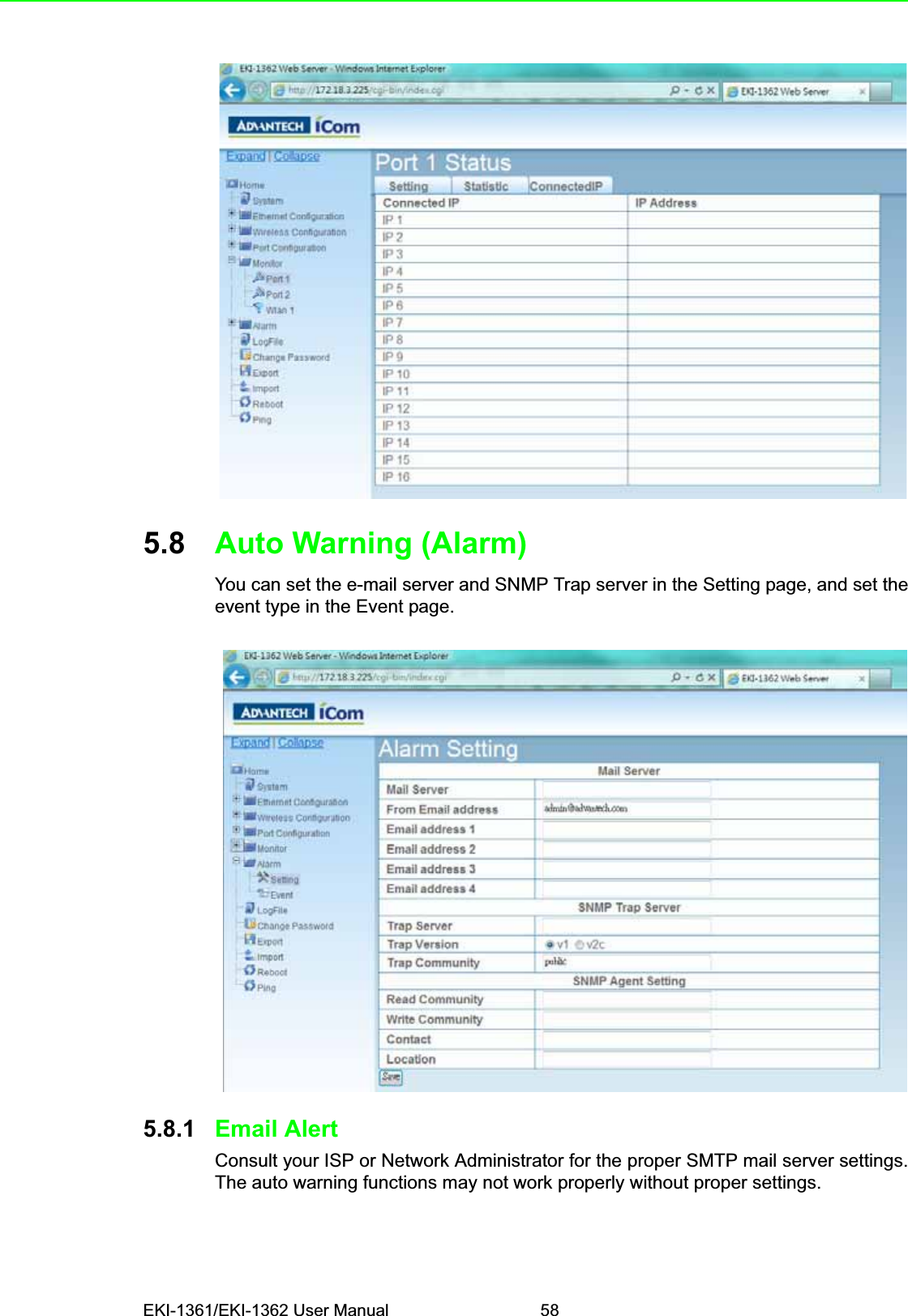

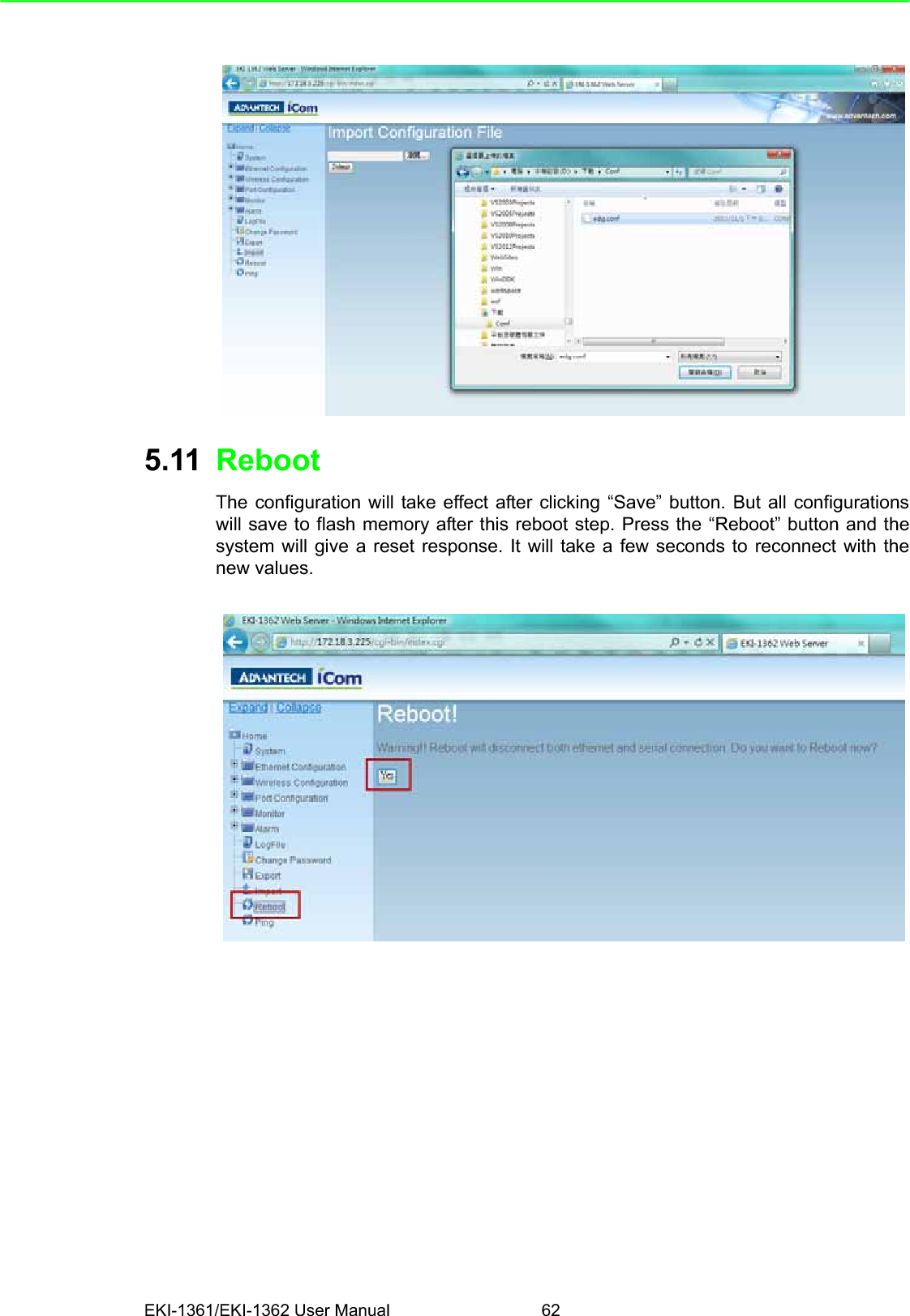
![EKI-1361/EKI-1362 User Manual 66HelpYou might type the “help” command or press <Tab> twice to show the supportedcommand list.[Usage] help[Function] Display help information of command listYou might use “help” command to show the usage of all commands.[Usage] help [command][Function] Show the usage of commandwirelessadv Show or configure the advanced wireless settings or informations](https://usermanual.wiki/Advantech-Co/EKI1362/User-Guide-2210809-Page-74.png)
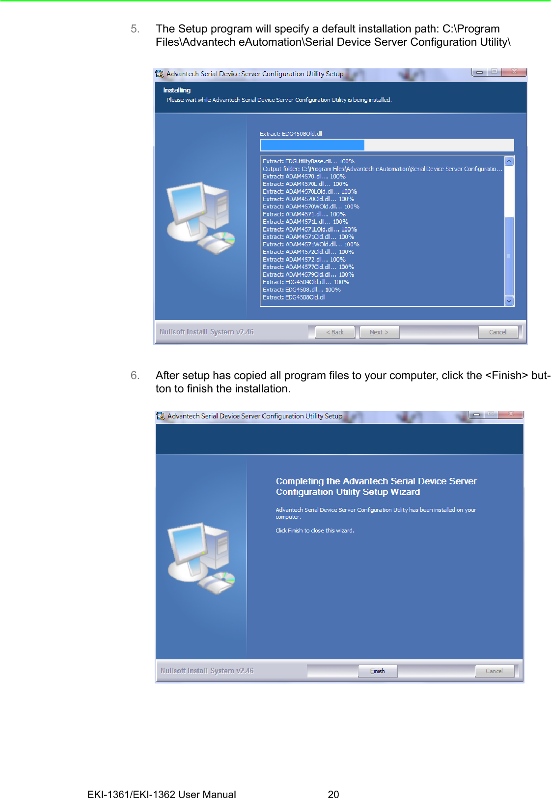
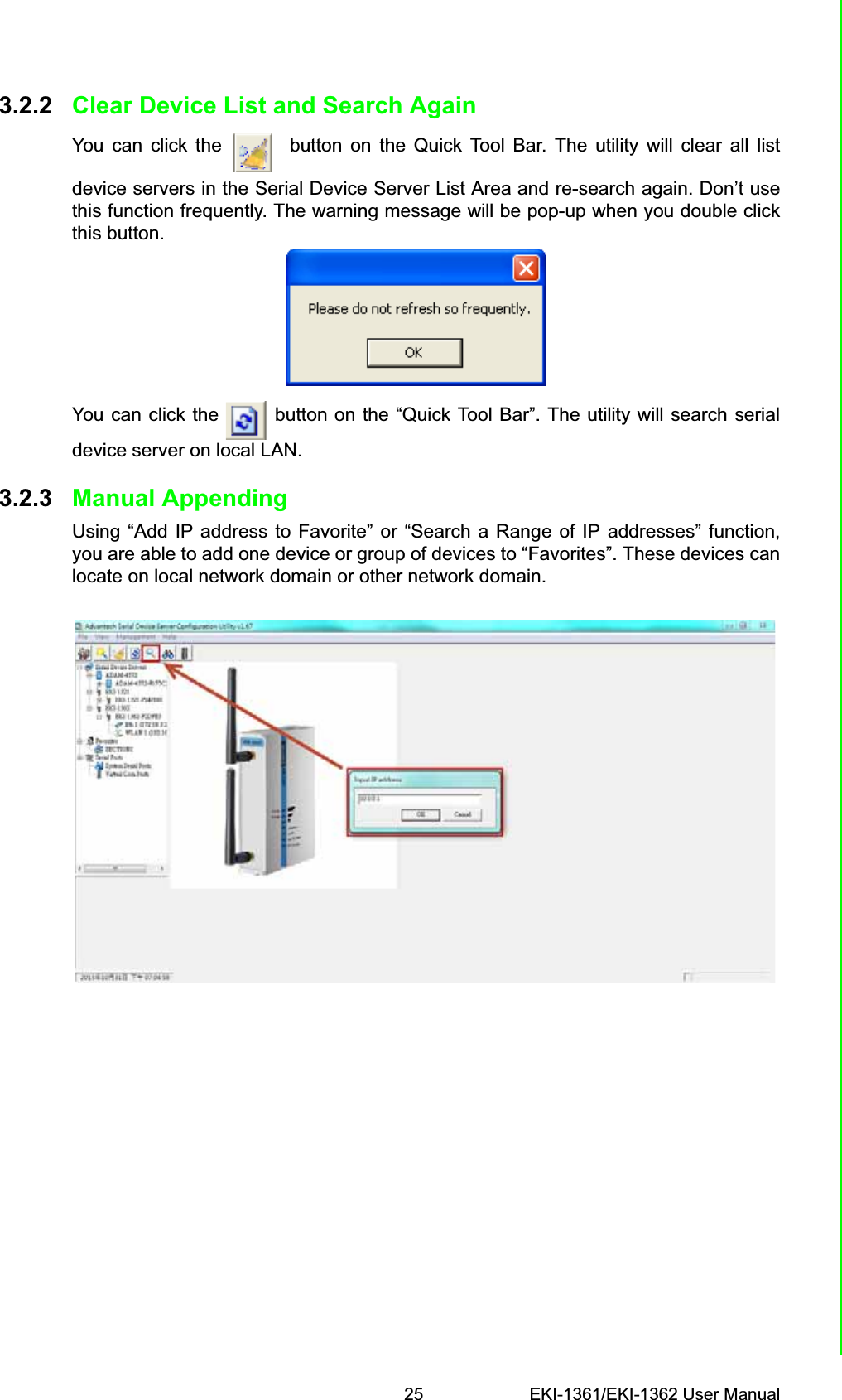
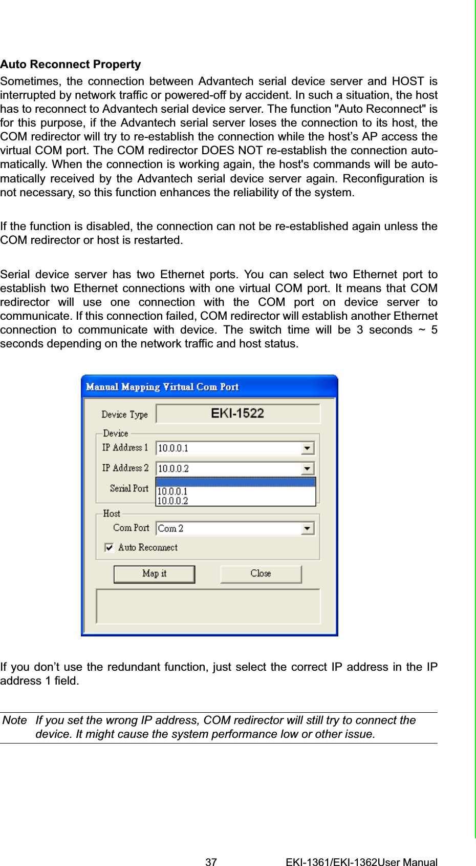
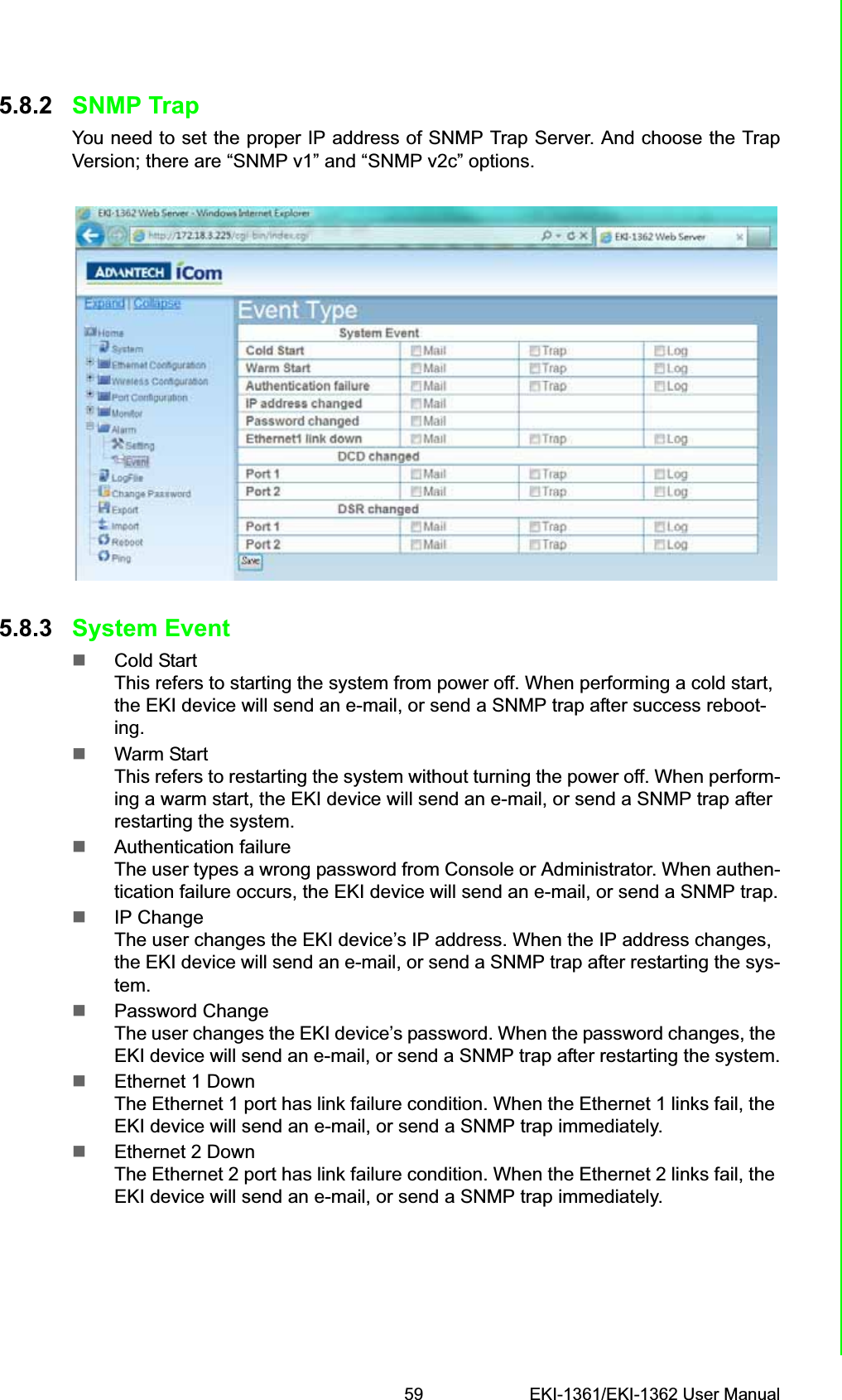
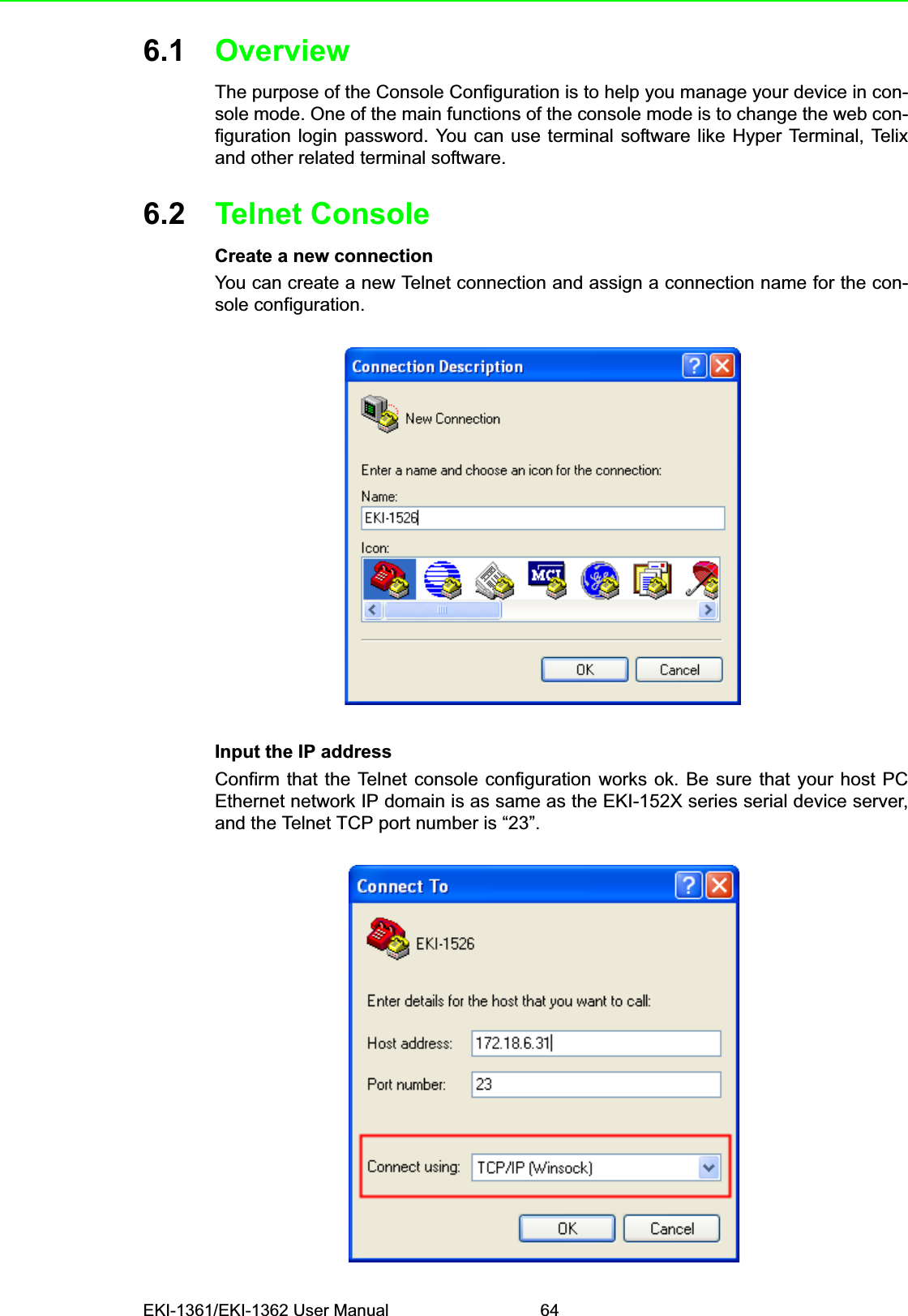
![67 EKI-1361/EKI-1362 User ManualChapter 6 Telnet ConfigurationSystem[Usage] system[Function] Show firmware version, device name and description[Usage] system[Function] Show current device status and information[Usage] system name XXXX[Function] Set current device name [XXXX: maximum length 31 bytes][Usage] system desc XXXX[Function] Set current device description [XXXX: maximum length 127 bytes]Port“Port” is the command to show all serial ports information and configure the serialports settings.](https://usermanual.wiki/Advantech-Co/EKI1362/User-Guide-2210809-Page-75.png)
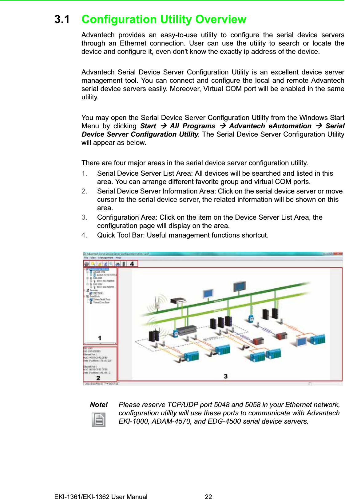
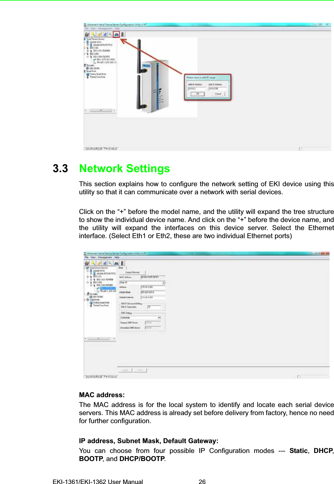
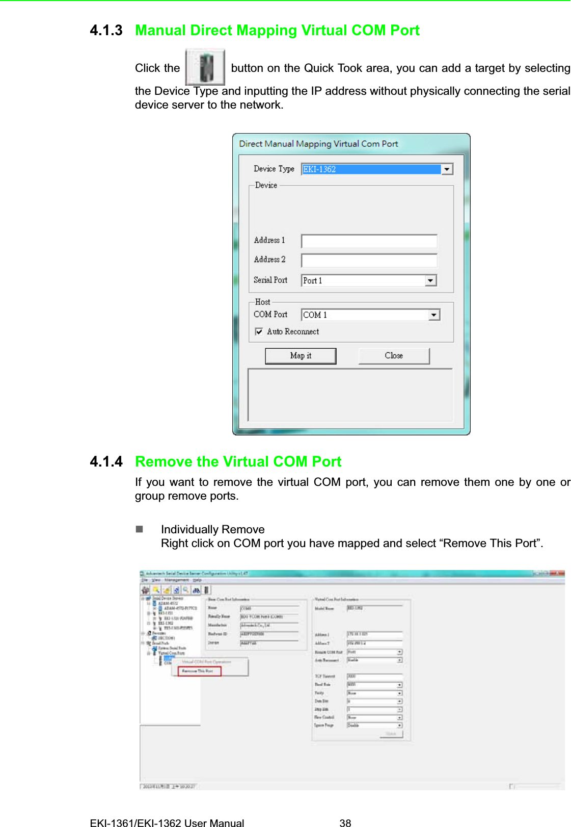
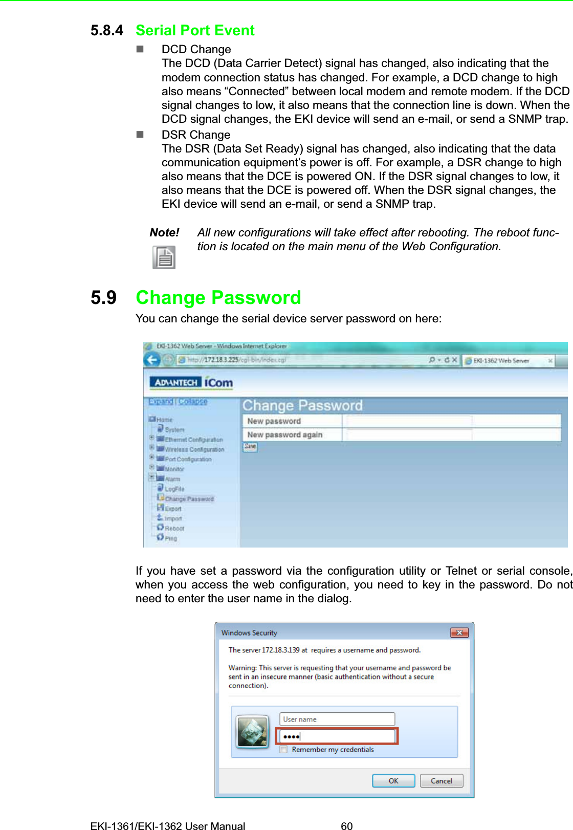
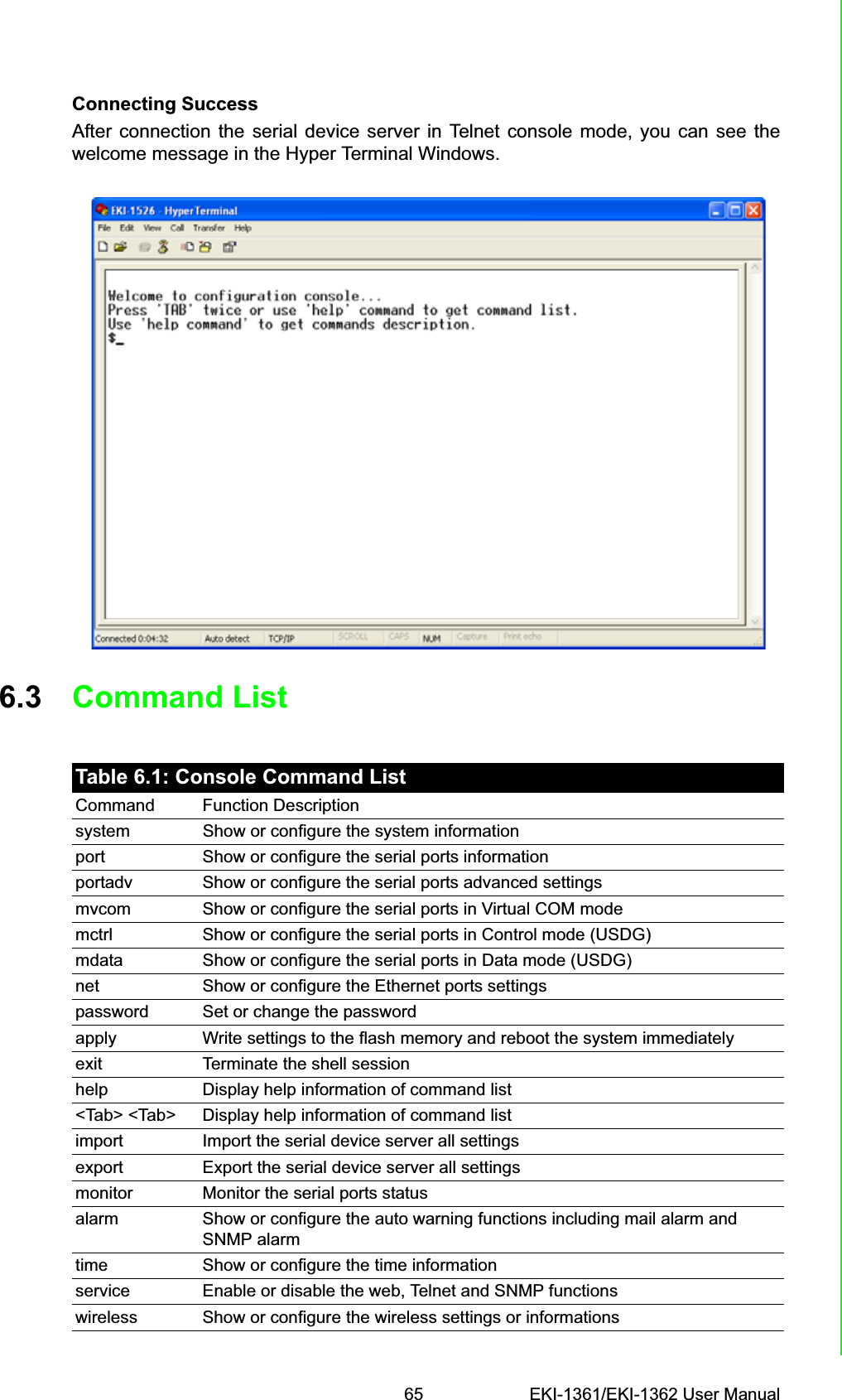
![EKI-1361/EKI-1362 User Manual 68[Usage] port nn or port all[Function] Show the “nn”th port or all ports information[Usage] port nn desc XXXX[Function] Set the “nn”th port’s description [XXXX: maximum length 127 bytes]](https://usermanual.wiki/Advantech-Co/EKI1362/User-Guide-2210809-Page-76.png)
![69 EKI-1361/EKI-1362 User ManualChapter 6 Telnet Configuration[Usage] port nn||all type 232|422|485 flow 0|1|2|3[Function] Set serial ports’ type and flow controlFlow 0: NoneFlow 1: XOn/XOffFlow2: RTS/CTSFlow3: DTR/DSR[Usage] port nn|all baud XXXX parity n|e|o|m|s data 5|6|7|8 stop 1|1.5|2[Function] Set the serial ports’ baud rate, parity, data bits, and stop bits.Acceptable baud rate: 50, 75, 110, 150, 300, 600, 1200, 1800, 2400, 4800, 7200,9600, 14400, 19200, 38400, 57600, 115200, 230400, 460800, and 921600Parity n: NoneParity e: EvenParity o: OddParity m: MarkParity s: Space[Usage] port nn|all mode vcom|ctrl|data[Function] Set the serial ports as virtual COM mode, control mode, or data modemvcomShow and setup the VCOM mode](https://usermanual.wiki/Advantech-Co/EKI1362/User-Guide-2210809-Page-77.png)
![EKI-1361/EKI-1362 User Manual 70[Usage] mvcom[Function] Show all serial ports mode and related information[Usage] mvcom nn|all[Function] Set the “nn”th or all serial ports as the Virtual COM mode[Usage] mvcom nn|all idleto XX[Function] Set the “nn”th or all serial ports host idle timeout (S)[Usage] mvcom nn|all respto XX framebk XX[Function] Set the “nn”th or all serial ports response timeout and frame breakmctrlShow and setup the Control mode[Usage] mctrl[Function] Show all serial ports mode and related information[Usage] mctrl nn|all[Function] Set the “nn”th or all serial ports as the Control mode[Usage] mctrl nn|all idleto XX guardt XX hangchr XX[Function] Set the “nn”th or all serial ports data idle timeout, guard time and hangcharacter](https://usermanual.wiki/Advantech-Co/EKI1362/User-Guide-2210809-Page-78.png)
![71 EKI-1361/EKI-1362 User ManualChapter 6 Telnet ConfigurationmdataShow and setup the Data mode[Usage] mdata[Function] Show all serial ports mode and related information[Usage] mdata nn|all[Function] Set the “nn”th or all serial ports as the Data mode[Usage] mdata nn|all protocol TCP|UDP[Function] Set the “nn”th or all serial ports’ transmit protocol as TCP or UDP[Usage] mdata nn|all idleto XX lsport XXXX atport XXXX[Function] Set the “nn”th or all serial ports data idle timeout, listen port, and AT com-mand port[Usage] mdata nn|all respto XX framebk XX[Function] Set the “nn”th or all serial ports response timeout and frame break[Usage] mdata nn|all peernum 1|2|3|4|5|6|7|8|9|10|11|12|13|14|15|16 peerXX.XX.XX.XX:ppp[Function] Set the peer IP address and port for receive data](https://usermanual.wiki/Advantech-Co/EKI1362/User-Guide-2210809-Page-79.png)
![EKI-1361/EKI-1362 User Manual 72netShow and setup the Ethernet port configuration[Usage] net 1|2[Function] Show the first or second Ethernet port status and information[Usage] net 1|2 mode static|dhcp|boot|all[Function] Set the network operating mode[Usage] net 1|2 ip XX.XX.XX.XX netmask XX.XX.XX.XX gw XX.XX.XX.XX[Function] Set IP address, subnet mask, and default gateway[Usage] net 1|2 dns auto|specific[Usage] net 1|2 dns1 XX.XX.XX.XX[Usage] net 1|2 dns2 XX.XX.XX.XX[Function] Set the DNS function](https://usermanual.wiki/Advantech-Co/EKI1362/User-Guide-2210809-Page-80.png)
![73 EKI-1361/EKI-1362 User ManualChapter 6 Telnet Configurationpassword[Usage] password new XXXX[Function] Set new password [XXXX: maximum 31 characters][Usage] password old XXXX new XXXX[Function] Confirm the old password and set a new passwordapply[Usage] apply[Function] Save the settings to the flash memory and reboot the system immediatelyexit[Usage] exit[Function] Terminate the shell sessionimport/export[Usage] import[Function] Import the serial device server settings’ file[Usage] export[Function] Export the serial device server settings’ file](https://usermanual.wiki/Advantech-Co/EKI1362/User-Guide-2210809-Page-81.png)
![EKI-1361/EKI-1362 User Manual 74monitorShow the serial ports settings, statistic, and connected IP address[Usage] monitor port 1|2|…|16 setting[Function] Monitor the serial ports settings[Usage] monitor port 1|2|…|16 statistic[Function] Monitor the serial ports statistic[Usage] monitor port 1|2…|16 ip[Function] Monitor the serial ports connected IP address](https://usermanual.wiki/Advantech-Co/EKI1362/User-Guide-2210809-Page-82.png)
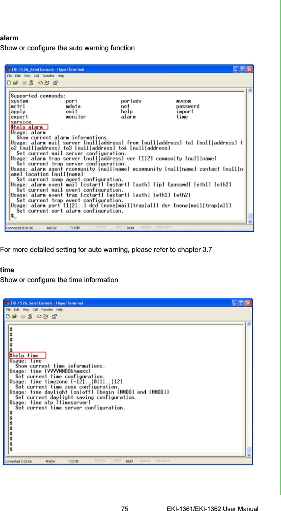
![EKI-1361/EKI-1362 User Manual 76[Usage] time[Function] Show the current time information[Usage] time YYYYMMDDhhmmss[Function] Modify the current time information[Usage] time timezone -12|…|0|1|…|12[Function] Set the current timezone configuration[Usage] time daylight on|off begin MMDD end MMDD[Function] Set the current time daylight saving configuration[Usage] time ntp XXXX[Function] Set the NTP timeserver [XXXX: time server]serviceEnable or disable some extra service[Usage] service web enable|disable[Function] Enable or disable the web-based configuration[Usage] service telnet enable|disable[Function] Enable or disable the telnet console[Usage] service SNMP enable|disable[Function] Enable or disable the SNMP function](https://usermanual.wiki/Advantech-Co/EKI1362/User-Guide-2210809-Page-84.png)
![77 EKI-1361/EKI-1362 User ManualChapter 6 Telnet ConfigurationwirelessShow or configure the wireless settings or informations[Usage] wireless[Function] Show or configure the wireless settings or informations[Usage] wireless ssid XXXX[Function]Set SSID as XXXX[Usage] wireless country us|de|fr|es|jp|kr|cn channel 0|1|…|14[Function] Set country code and channel. us - United Statesde – Germanyfr – Francees - Spain jp – Japankr – Koreacn - China channel 0 - Auto[Usage] wireless encryption none|wep|wpa-psk|wpa-enterprise[Function] Set encryption type.[Usage] wireless wepauth on|off[Function] Set WEP authentication algorithm.[Usage] wireless wepidx 0|1|2|3[Function] Set WEP key index.[Usage] wireless wepkey asc|hex XXXX[Function] Set WEP key as XXXX in specific format[Usage] wireless wpakey XXXX[Function] Set WPA-PSK key as XXXX[Usage] wireless wpaeap tls|ttls|peap[Function] Set WPA-Enterprise EAP method.[Usage] wirelesswpa11w 0|1|2[Function] Set WPA-Enterprise management frame protected. 0 – Disable1 – Optional2 – Required[Usage] wireless wpaid XXXX[Function] Set WPA-Enterprise identity as XXXX.](https://usermanual.wiki/Advantech-Co/EKI1362/User-Guide-2210809-Page-85.png)
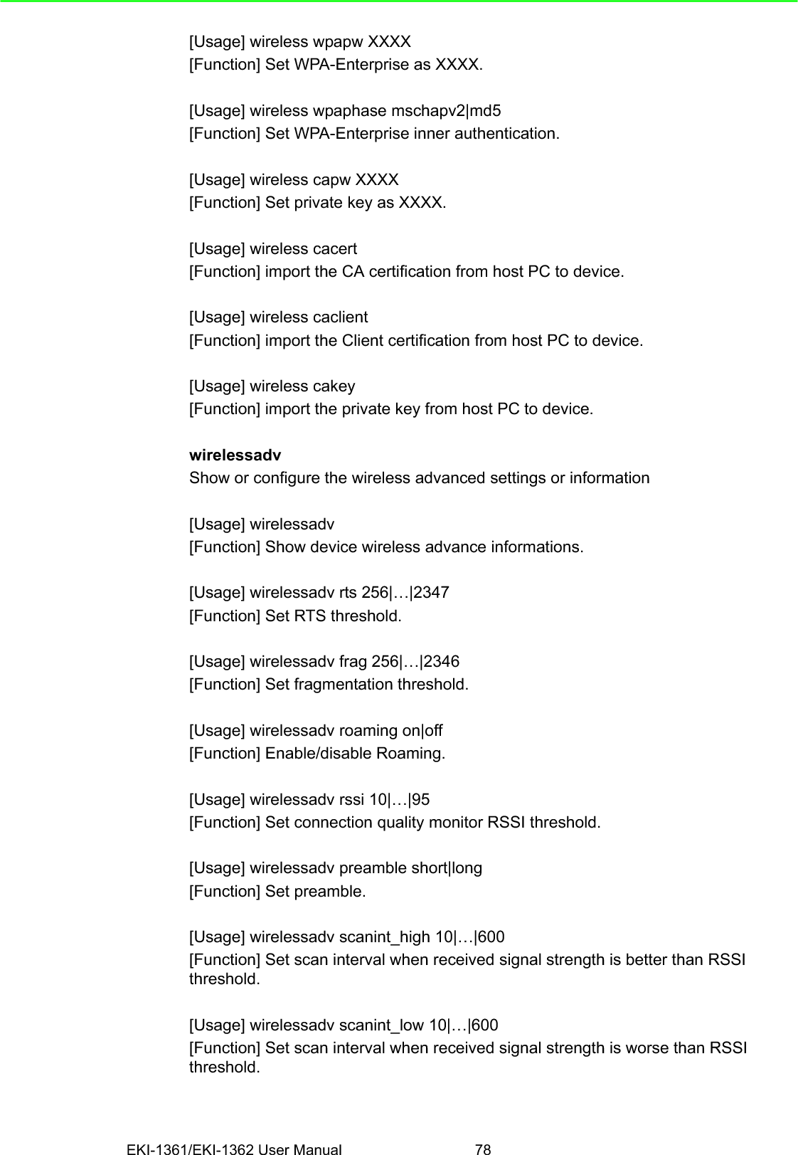
![EKI-1361/EKI-1362 User Manual 78[Usage] wireless wpapw XXXX[Function] Set WPA-Enterprise as XXXX.[Usage] wireless wpaphase mschapv2|md5[Function] Set WPA-Enterprise inner authentication.[Usage] wireless capw XXXX[Function] Set private key as XXXX.[Usage] wireless cacert[Function] import the CA certification from host PC to device.[Usage] wireless caclient[Function] import the Client certification from host PC to device.[Usage] wireless cakey[Function] import the private key from host PC to device.wirelessadvShow or configure the wireless advanced settings or information[Usage] wirelessadv[Function] Show device wireless advance informations.[Usage] wirelessadv rts 256|…|2347[Function] Set RTS threshold.[Usage] wirelessadv frag 256|…|2346[Function] Set fragmentation threshold.[Usage] wirelessadv roaming on|off[Function] Enable/disable Roaming.[Usage] wirelessadv rssi 10|…|95[Function] Set connection quality monitor RSSI threshold.[Usage] wirelessadv preamble short|long[Function] Set preamble.[Usage] wirelessadv scanint_high 10|…|600[Function] Set scan interval when received signal strength is better than RSSI threshold.[Usage] wirelessadv scanint_low 10|…|600[Function] Set scan interval when received signal strength is worse than RSSI threshold.](https://usermanual.wiki/Advantech-Co/EKI1362/User-Guide-2210809-Page-86.png)