Advantech Co EKI1362BE Ethernet Device User Manual EKI 1360 BE Series UM
Advantech Co Ltd Ethernet Device EKI 1360 BE Series UM
UserManual.wiki
>
Advantech Co
>
EKI1362BE User Manual
User Manual
Navigation menu
Upload a User Manual
Namespaces
Wiki Guide
HTML
PDF
Info
Views
User Manual
Discussion / Help
Navigation

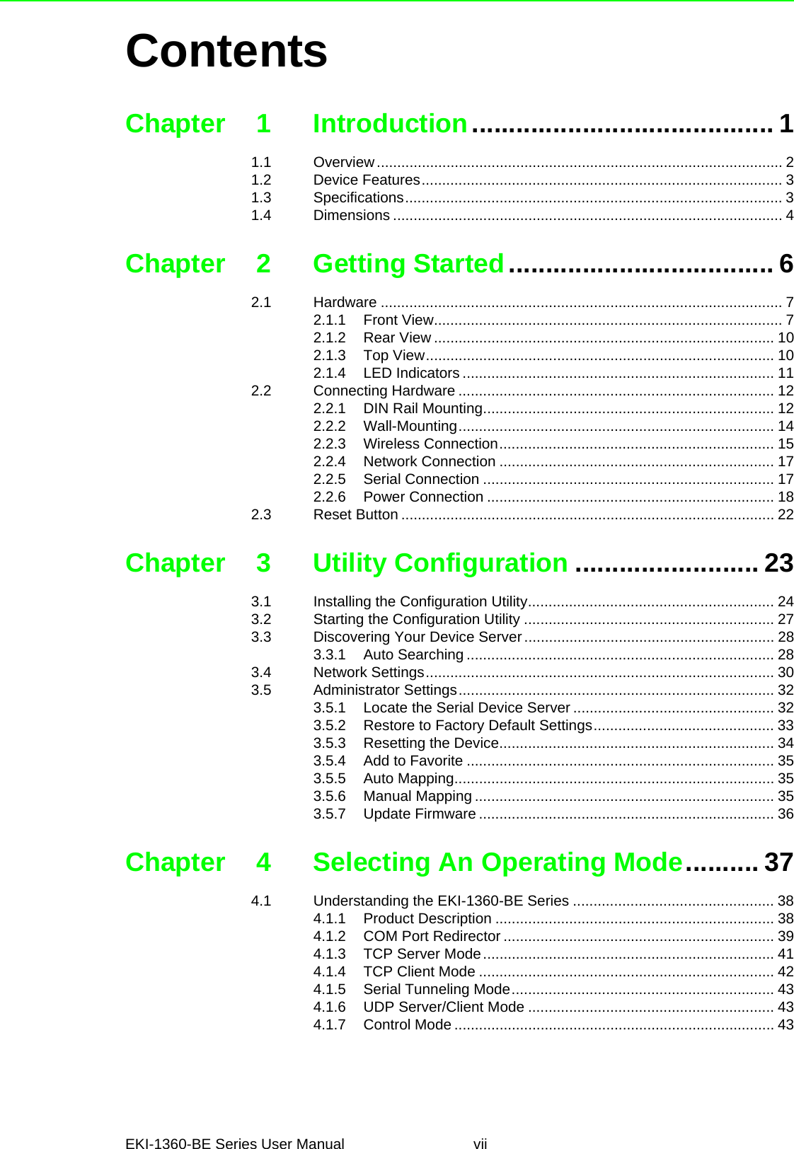
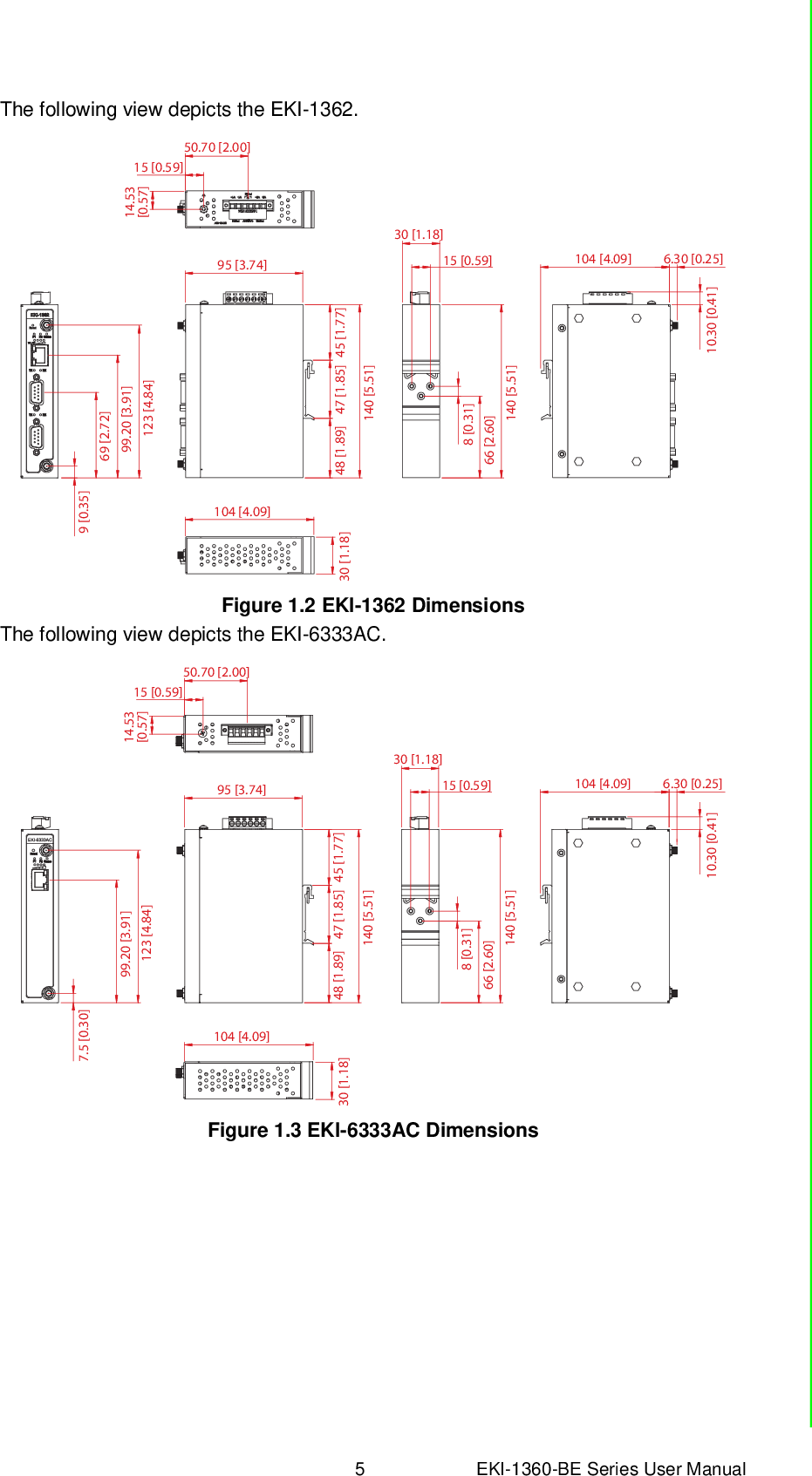
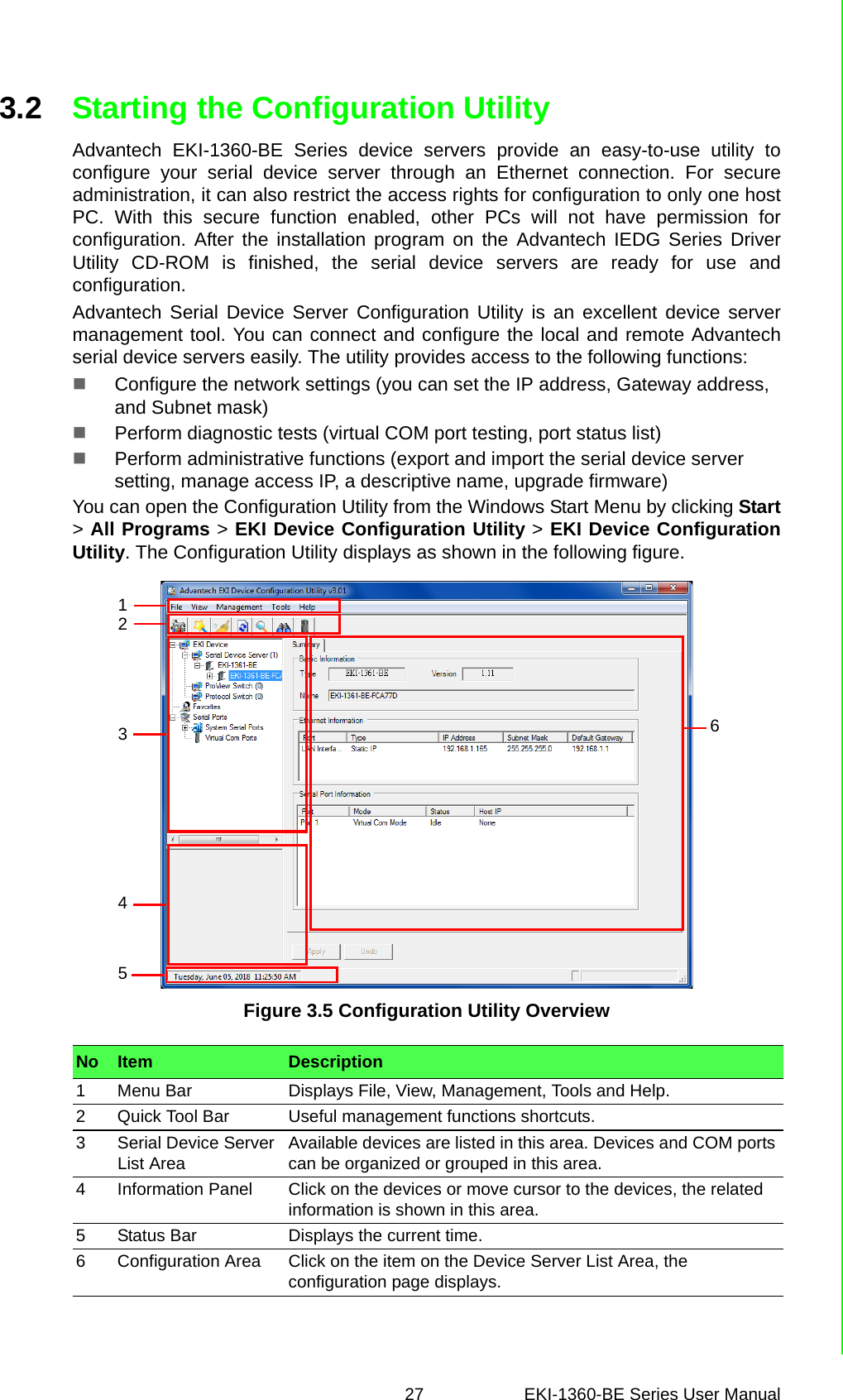
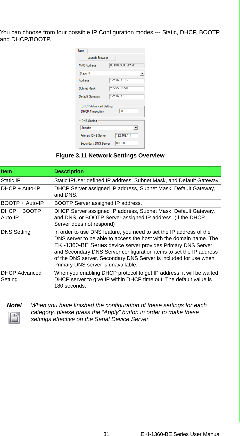
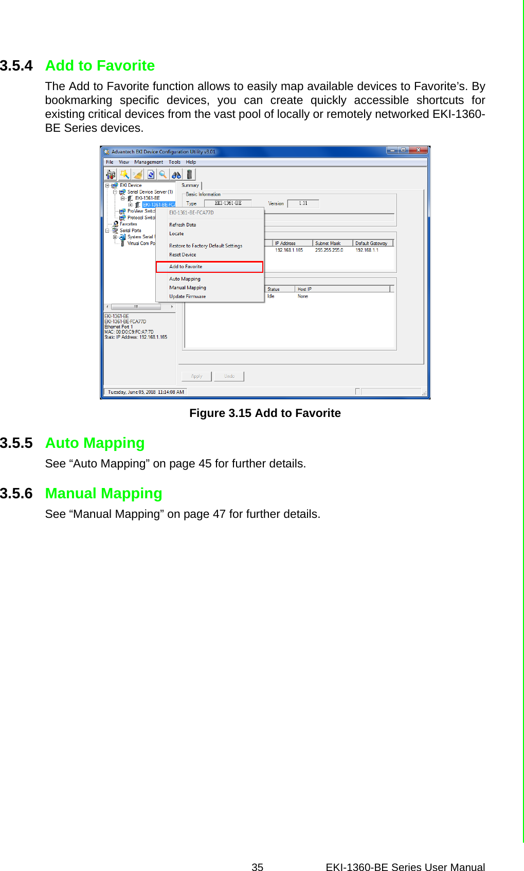
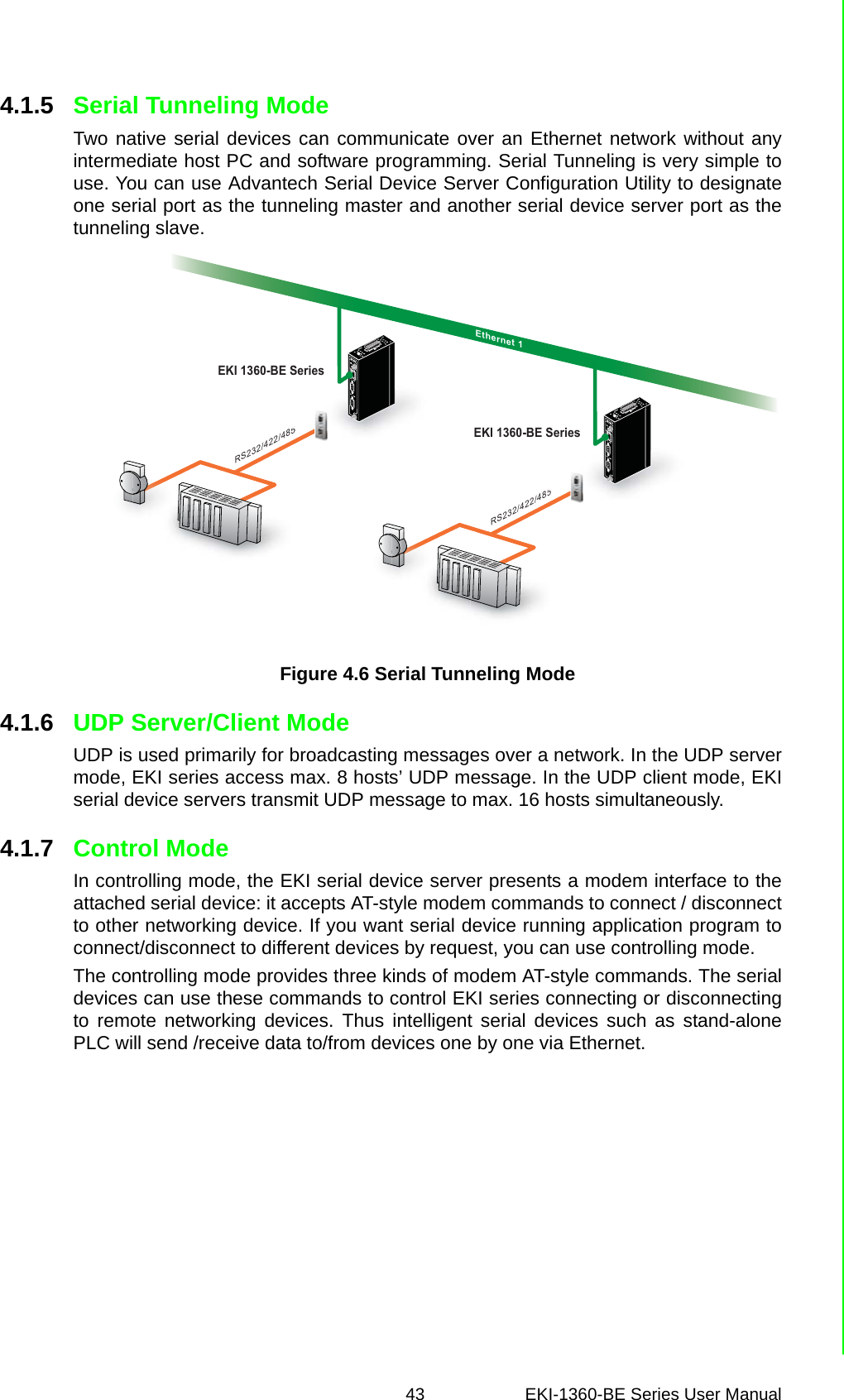
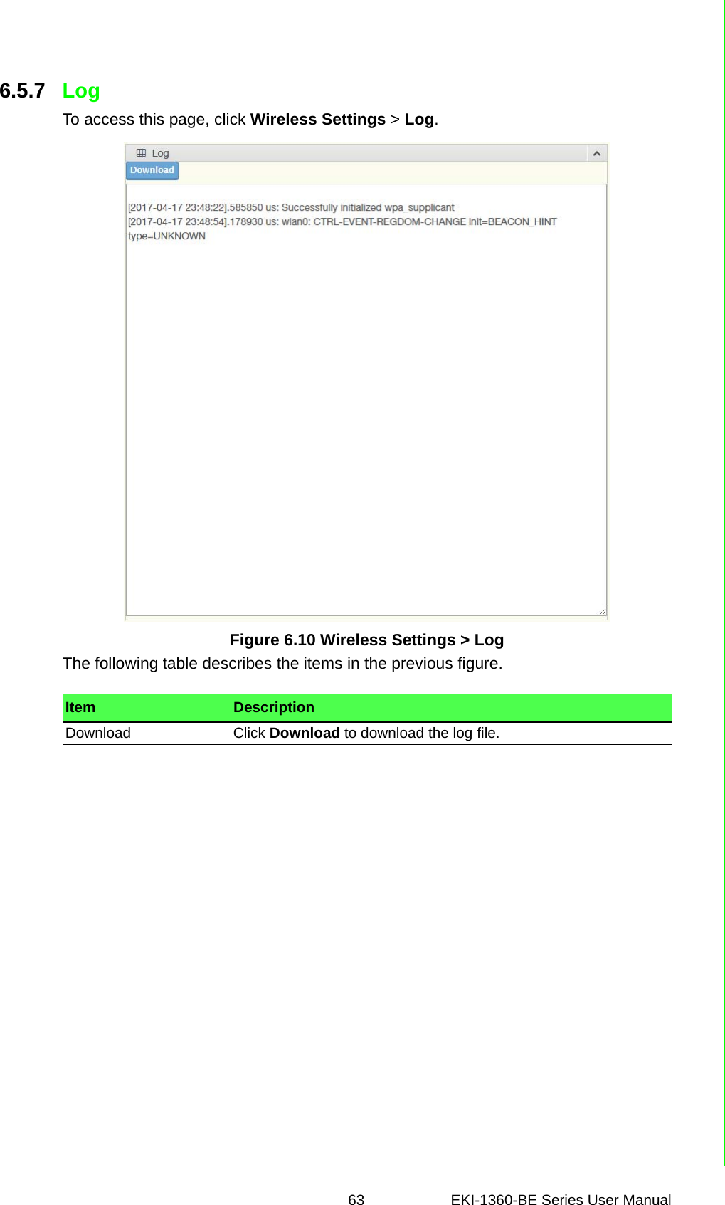
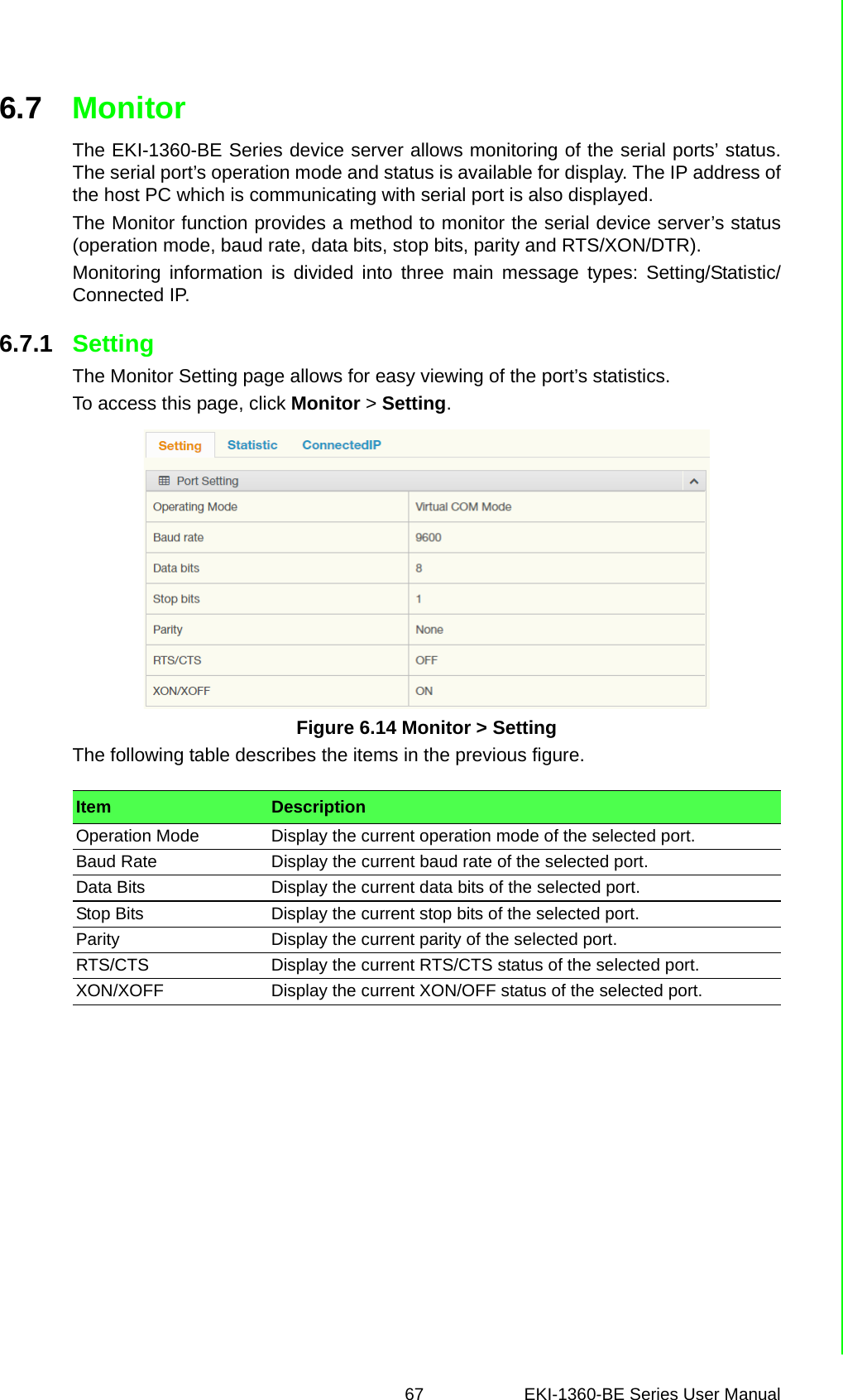
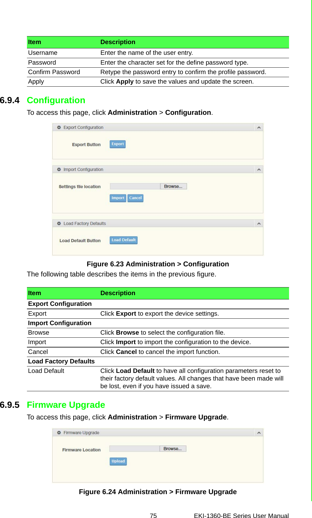
![EKI-1360-BE Series User Manual 41.4 DimensionsThe following view depicts the EKI-1361.Figure 1.1 EKI-1361 DimensionsSerial Communications Port Type RS-232/422/485, software selectablePort Connector DB9 maleData Bits 5, 6, 7, 8Stop Bits 1, 1.5, 2Parity None, Odd, Even, Space, MarkBaud Rate 50 bps ~ 921.6 kbps, any baud rate settingProtection 15 KV ESD for all signalsPower Power ConsumptionEKI-1361: 8WEKI-1362: 9WPower Input 12 ~ 48VDC, redundant dual inputsSoftware Driver Support 32-bit/64-bit Windows XP/Vista/7/8/8.1/10, Windows Server 2003/2008/2008 R2/2012/2012 R2 and LinuxUtility Advantech EKI Device Configuration UtilityOperation Modes Access Point mode/Station modeCOM port redirection mode (Virtual COM)TCP/UDP server (polling) modeTCP/UDP client (event handling) modeConfiguration Windows utility, Telnet console, Web BrowserProtocol ARP, ICMP, IPv4, IPv6, TCP, UDP, BOOTP, DHCP Client, Auto IP, Telnet, DNS, SNMP, HTTP, SMTP, SNTPRegulatory Approvals EMC CE, FCC Part 15 Subpart B (Class B)Specifications DescriptionResetWLAN50.70 [2.00]95 [3.74]69 [2.72]99.20 [3.91]123 [4.84]30 [1.18]30 [1.18]140 [5.51]140 [5.51]66 [2.60]8 [0.31]10.30 [0.41]104 [4.09] 6.30 [0.25]48 [1.89] 47 [1.85] 45 [1.77]104 [4.09]15 [0.59]15 [0.59]14.53[0.57]9 [0.35]](https://usermanual.wiki/Advantech-Co/EKI1362BE/User-Guide-4020599-Page-15.png)
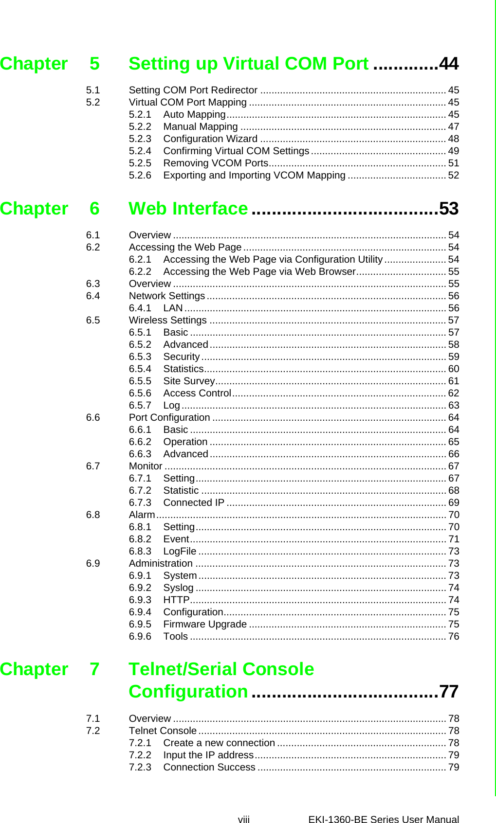
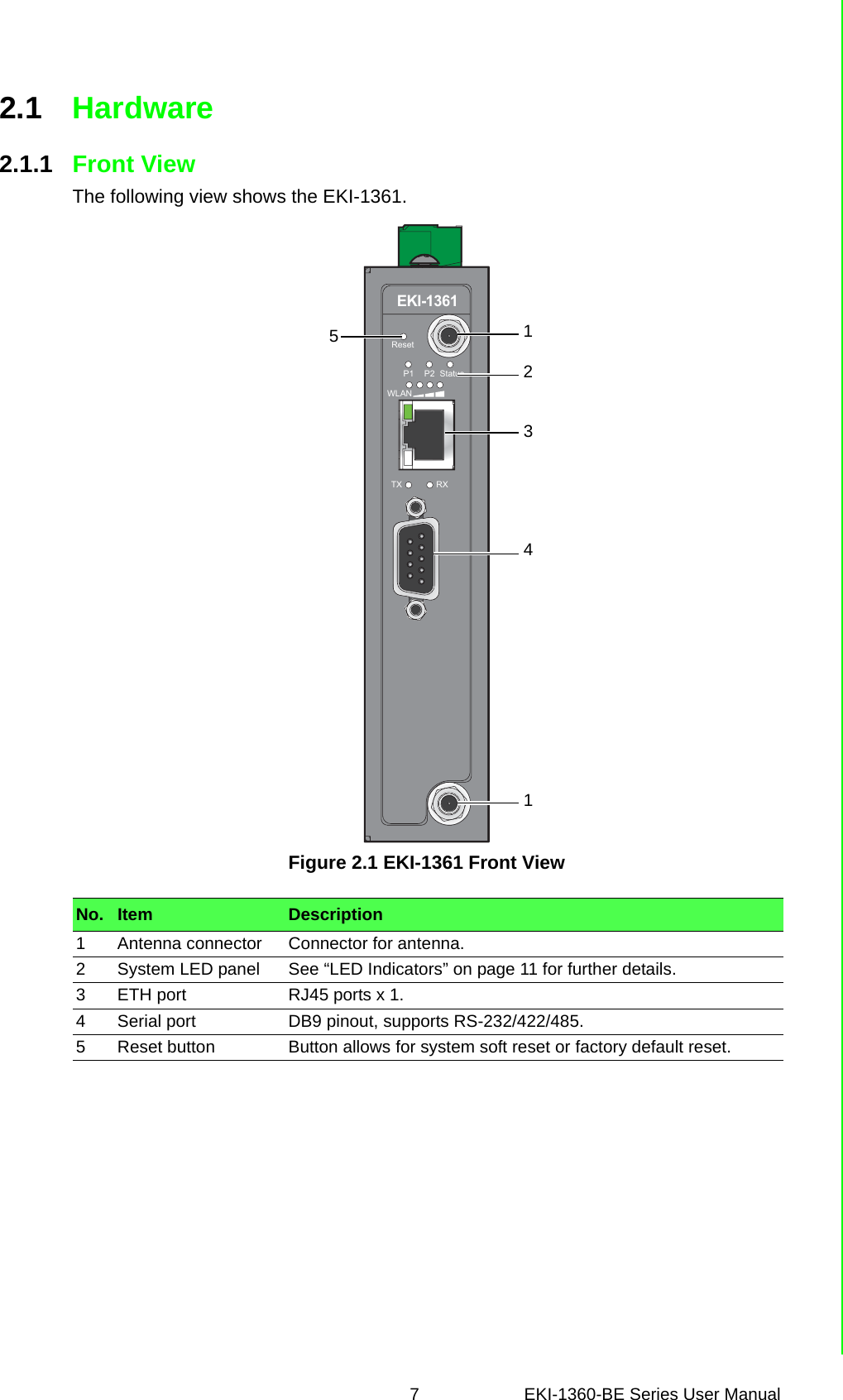
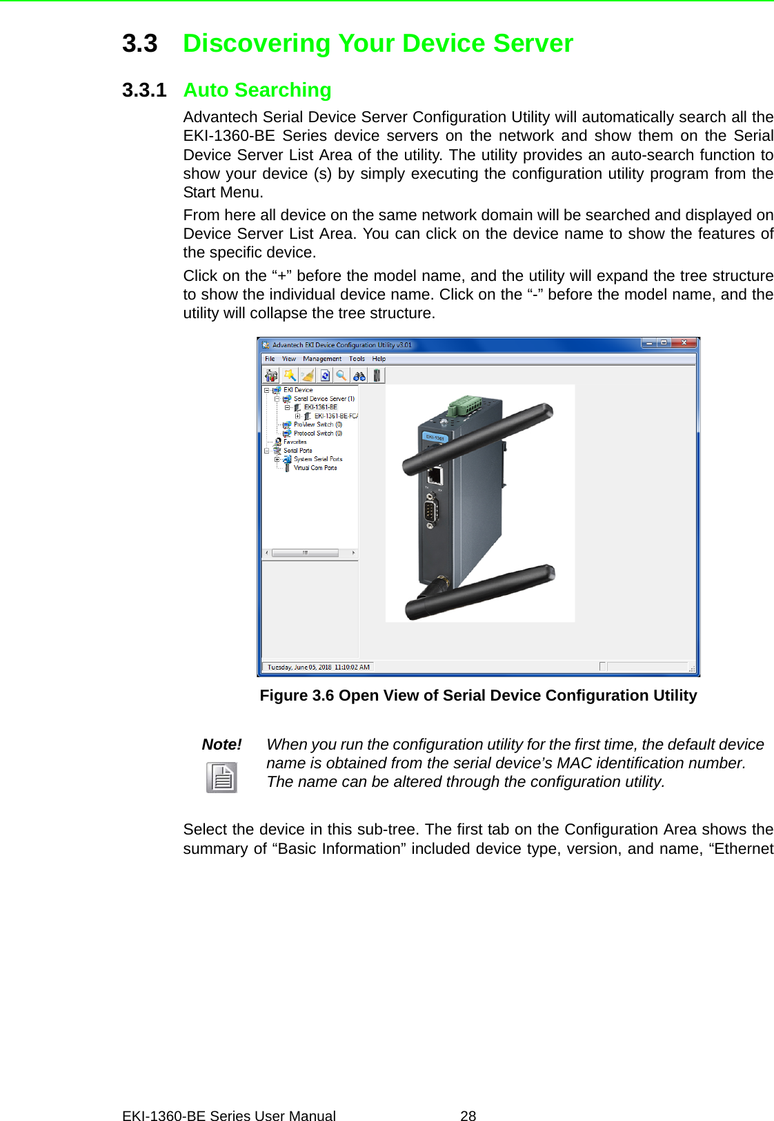
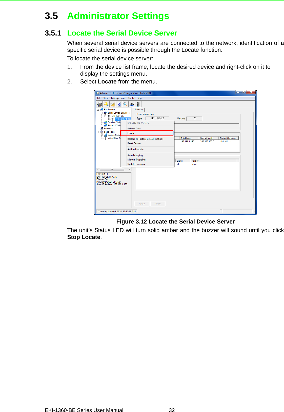
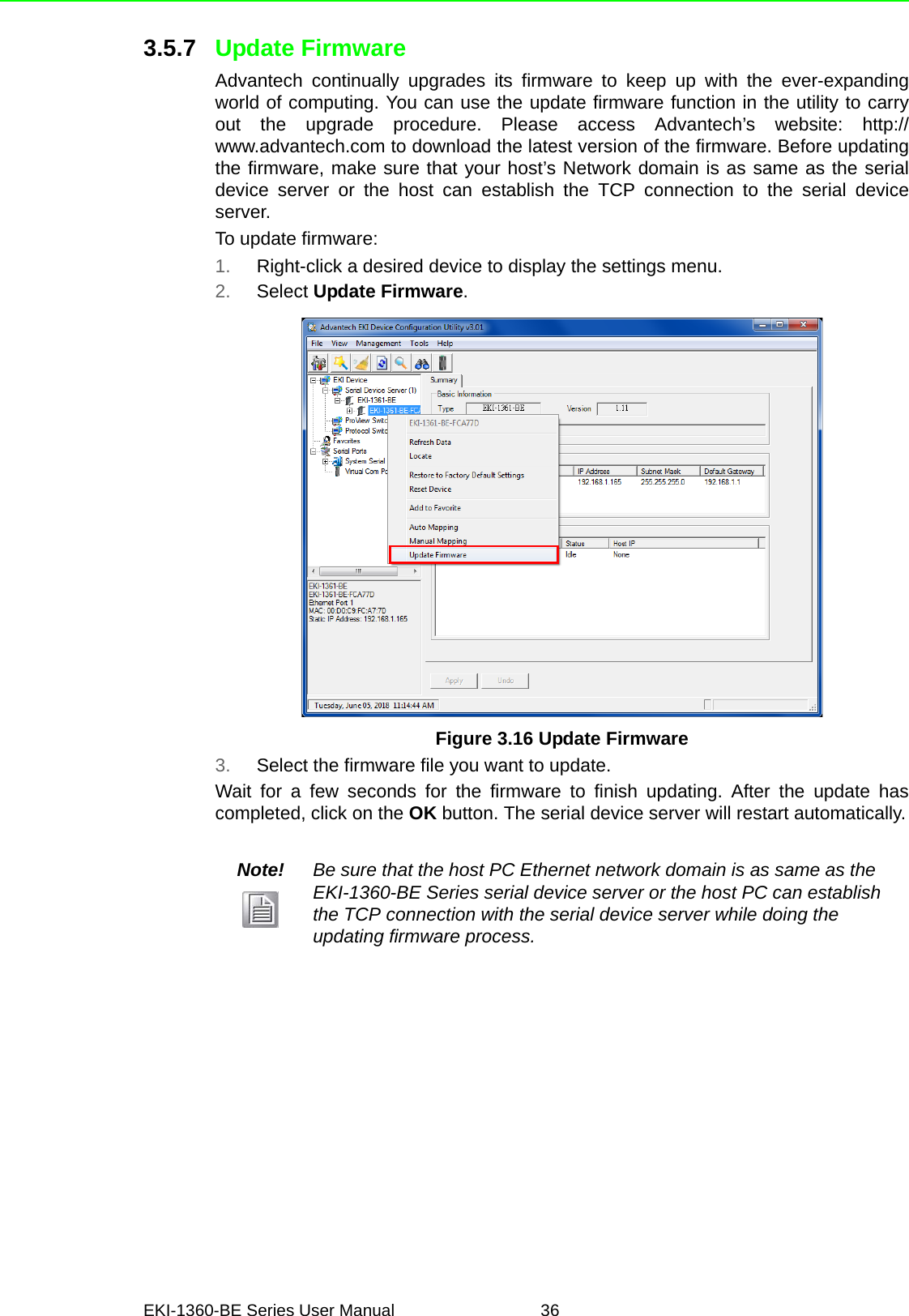
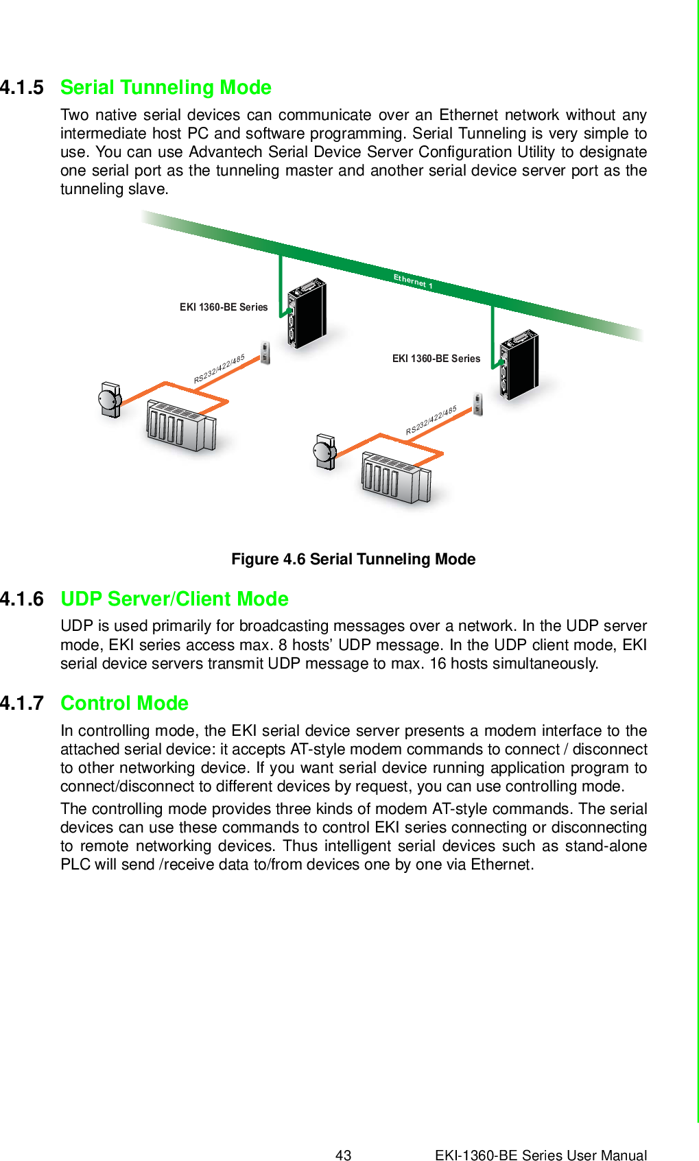
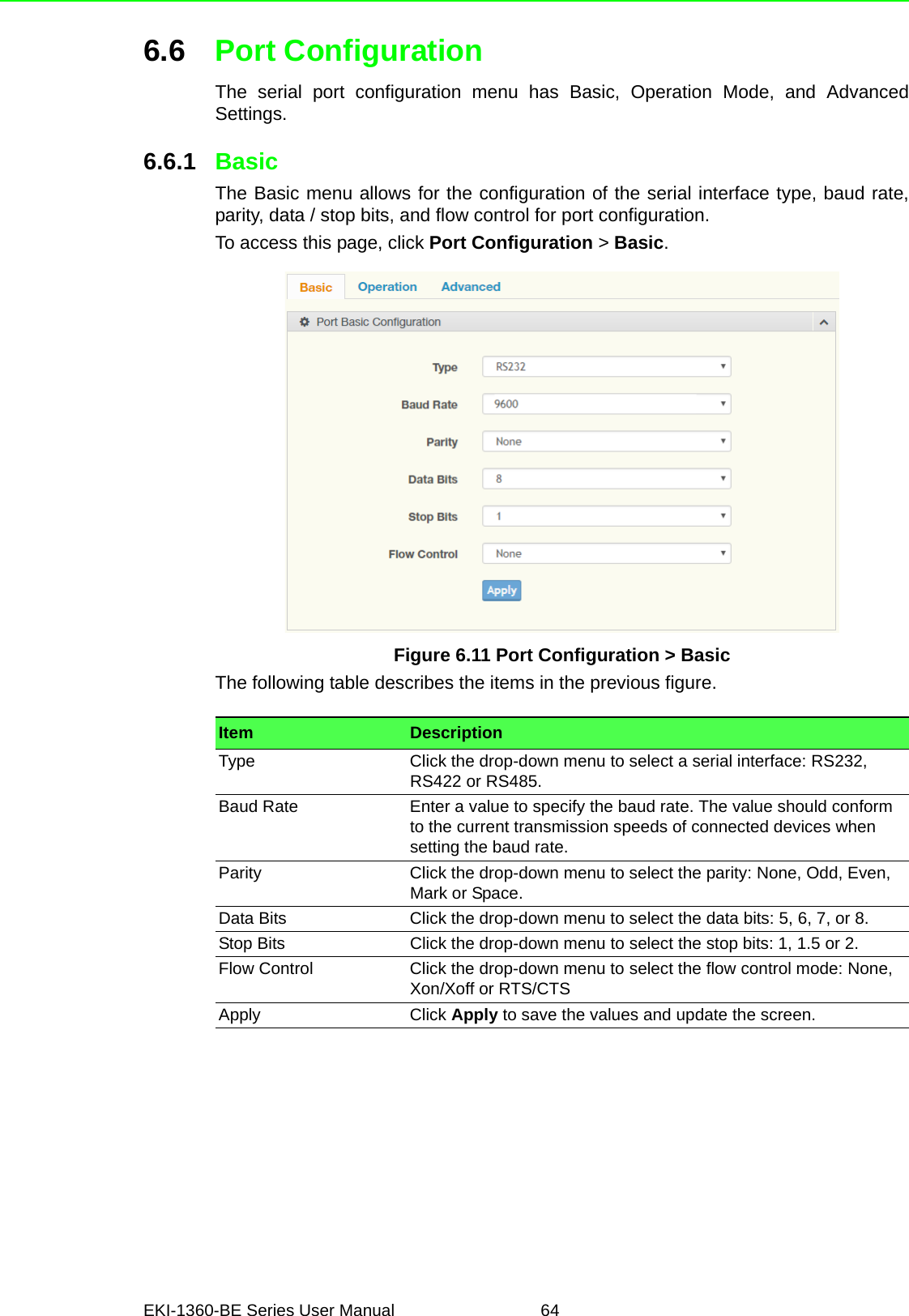
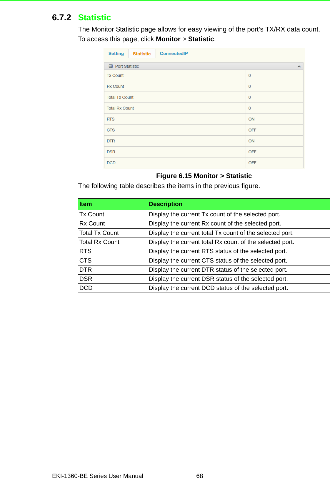
![5 EKI-1360-BE Series User Manual The following view depicts the EKI-1362.Figure 1.2 EKI-1362 DimensionsThe following view depicts the EKI-6333AC.Figure 1.3 EKI-6333AC DimensionsResetWLAN50.70 [2.00]95 [3.74]69 [2.72]99.20 [3.91]123 [4.84]30 [1.18]30 [1.18]140 [5.51]140 [5.51]66 [2.60]8 [0.31]10.30 [0.41]104 [4.09] 6.30 [0.25]48 [1.89] 47 [1.85] 45 [1.77]104 [4.09]15 [0.59]15 [0.59]14.53[0.57]9 [0.35]50.70 [2.00]95 [3.74]99.20 [3.91]123 [4.84]30 [1.18]30 [1.18]140 [5.51]140 [5.51]66 [2.60]8 [0.31]10.30 [0.41]104 [4.09] 6.30 [0.25]48 [1.89] 47 [1.85] 45 [1.77]104 [4.09]15 [0.59]15 [0.59]14.53[0.57]7.5 [0.30]](https://usermanual.wiki/Advantech-Co/EKI1362BE/User-Guide-4020599-Page-16.png)
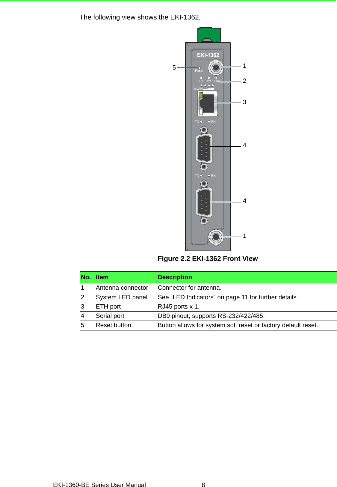


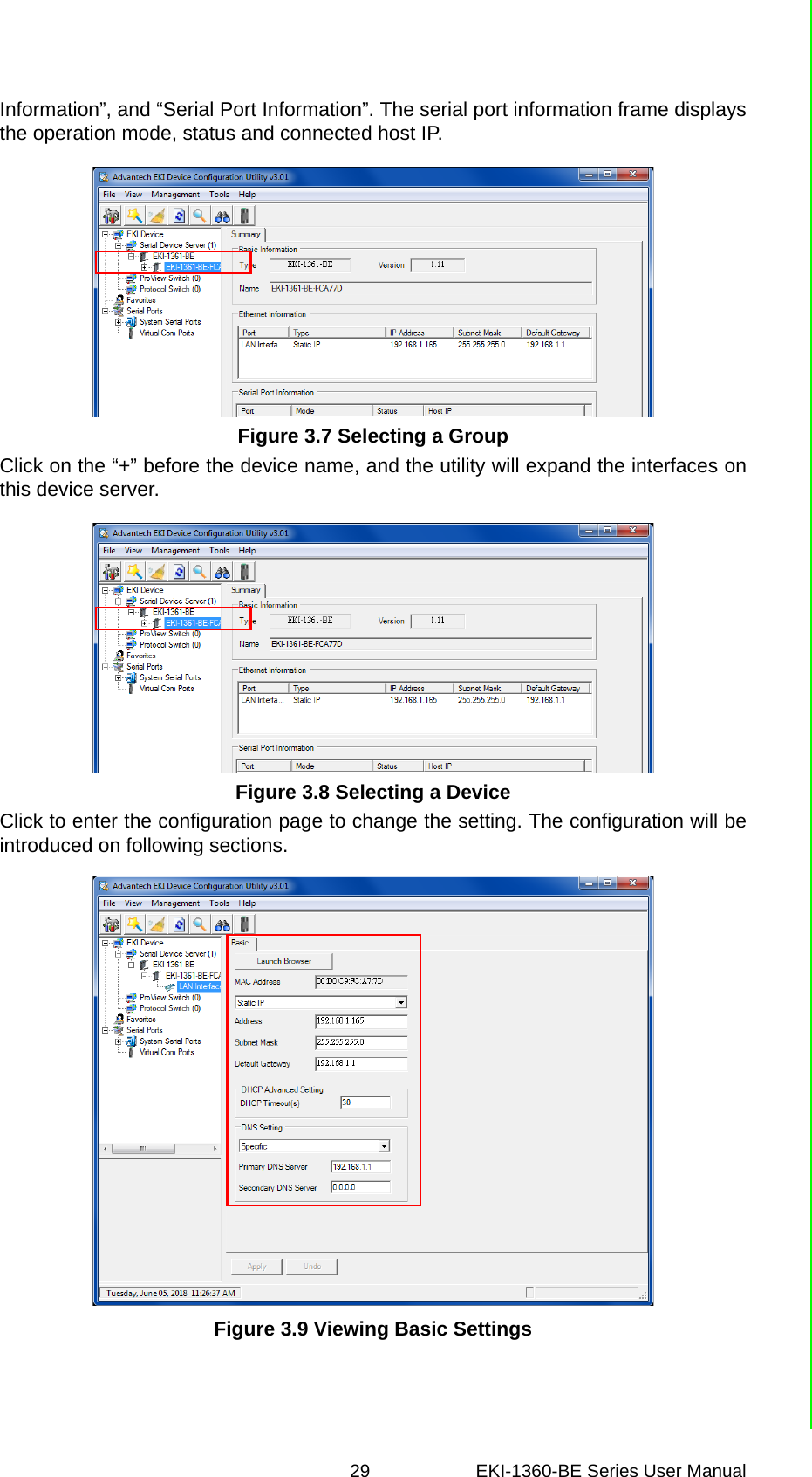
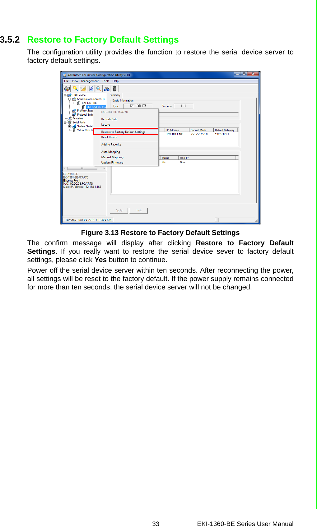
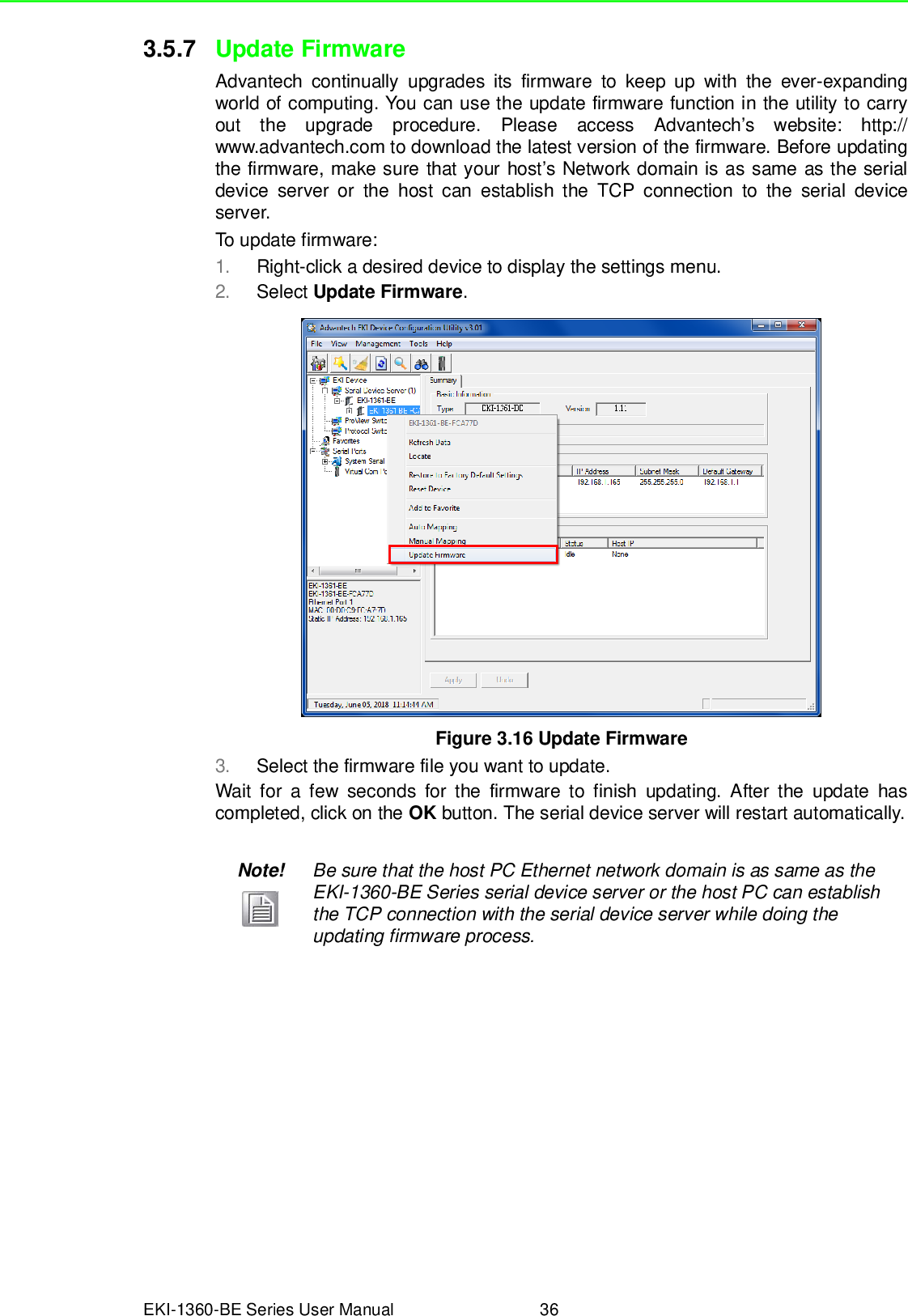
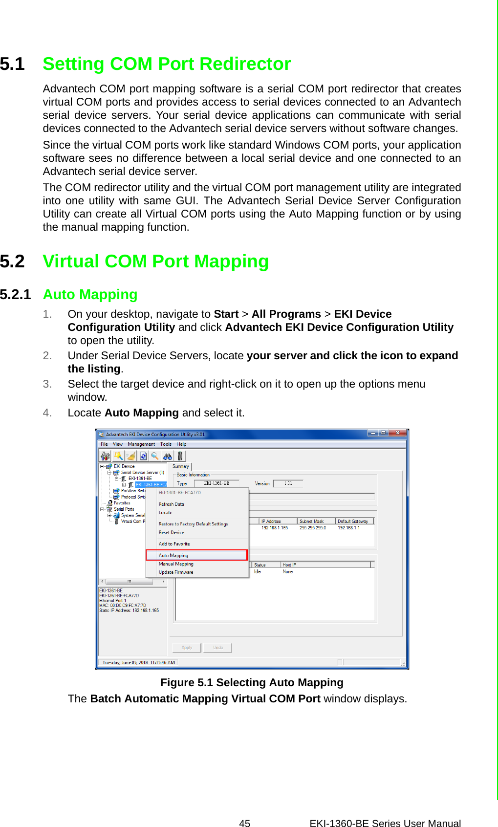
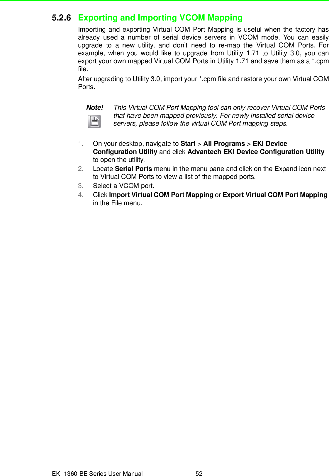
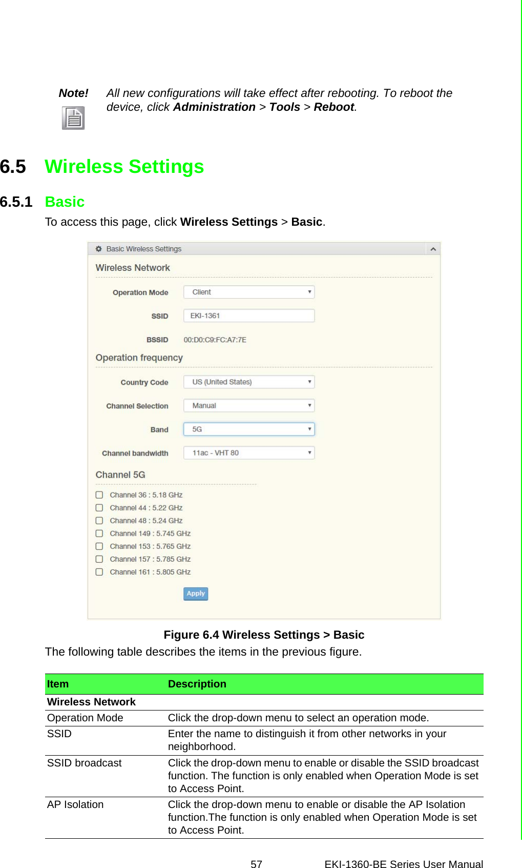
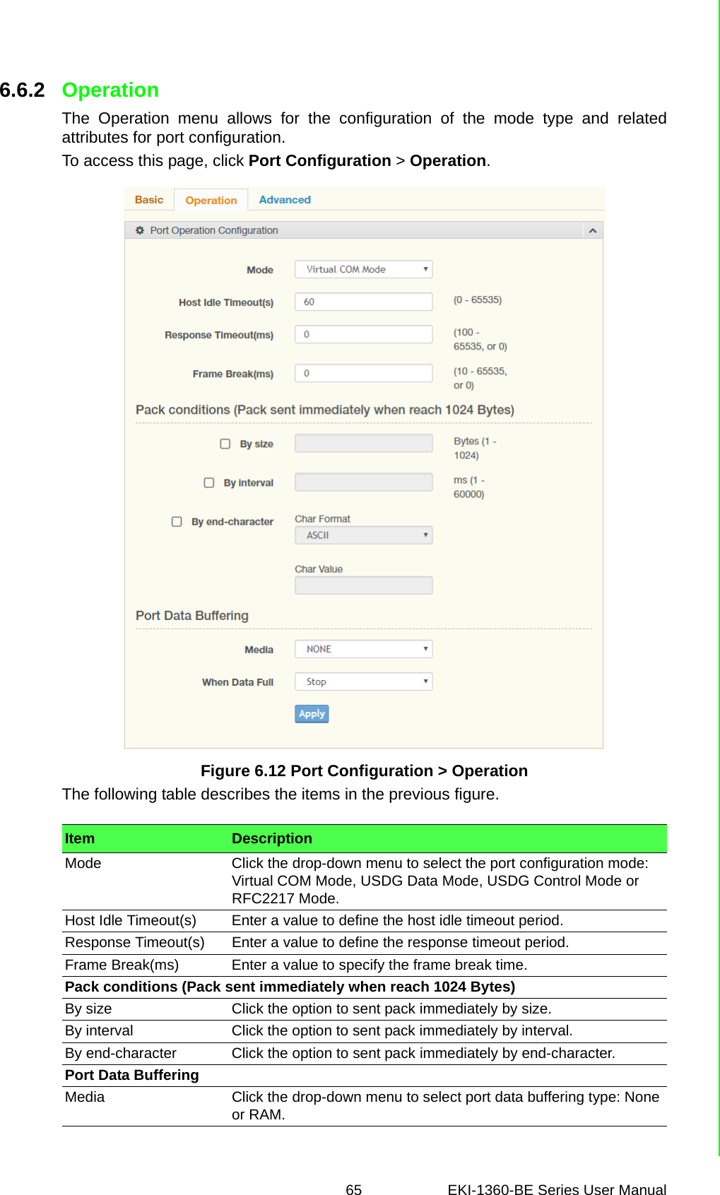
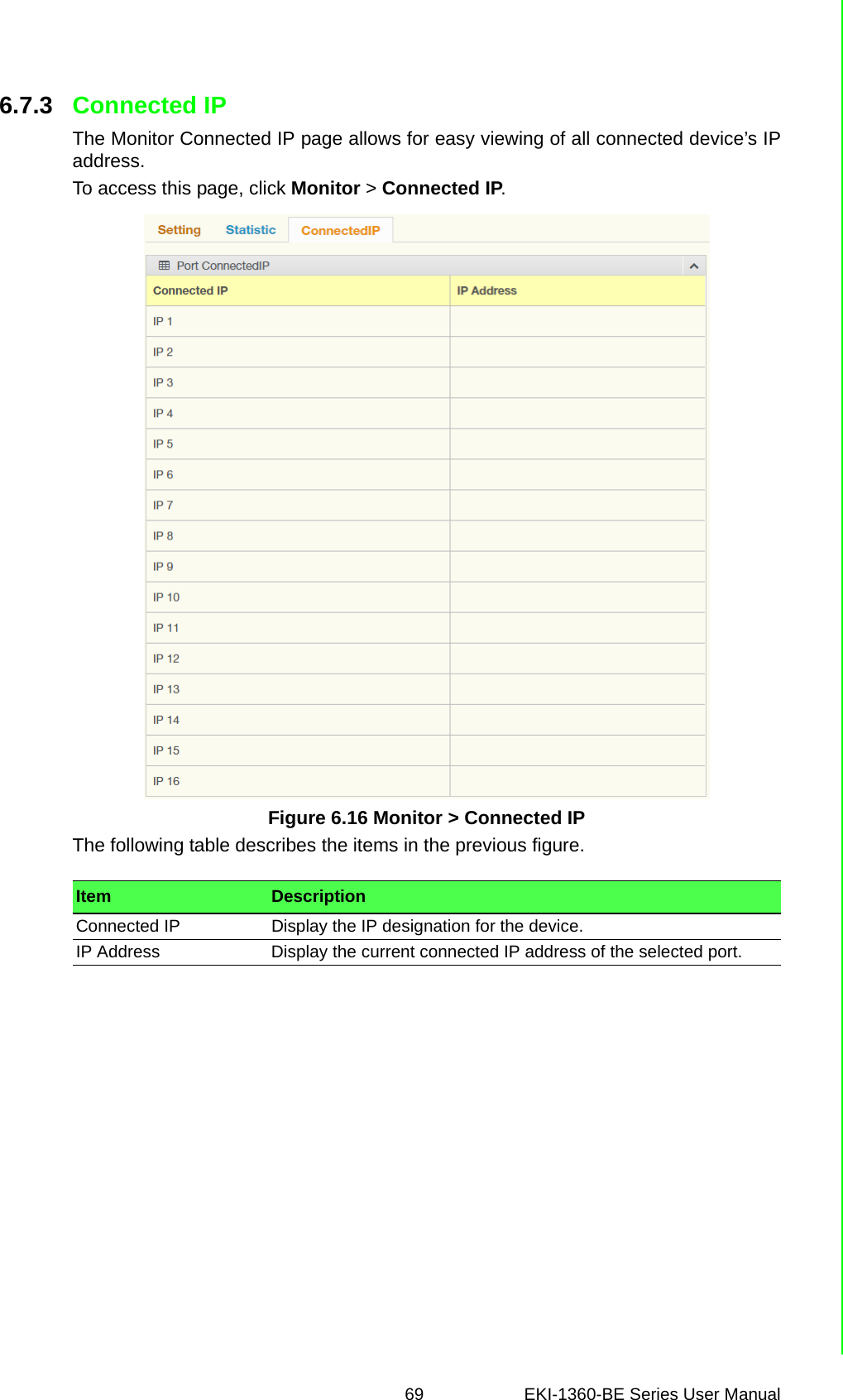

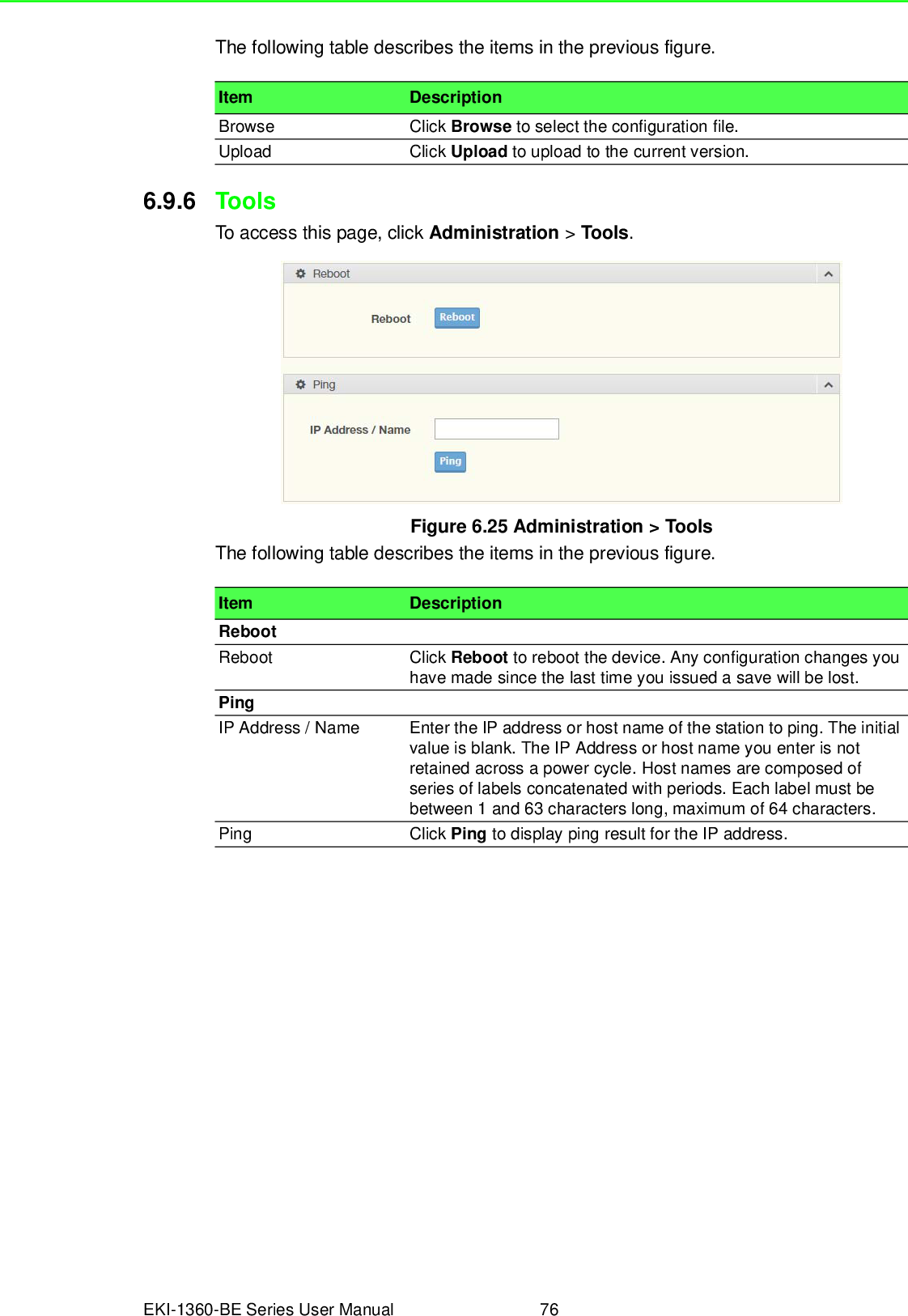
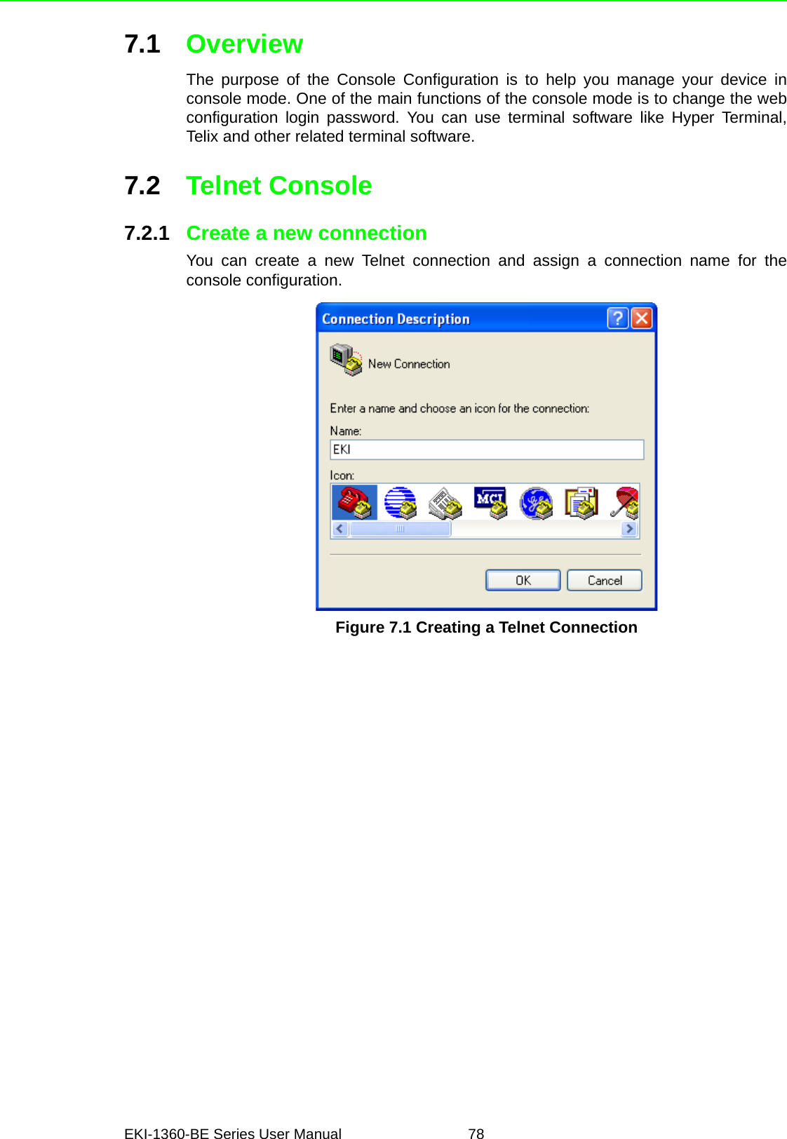
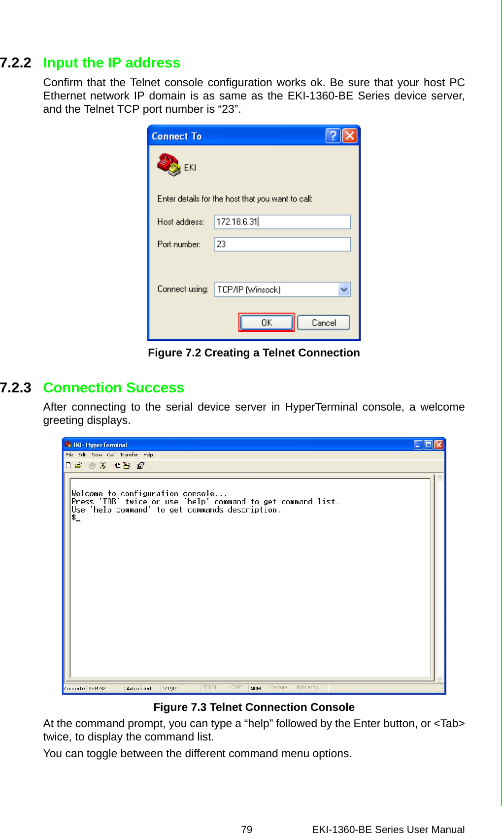
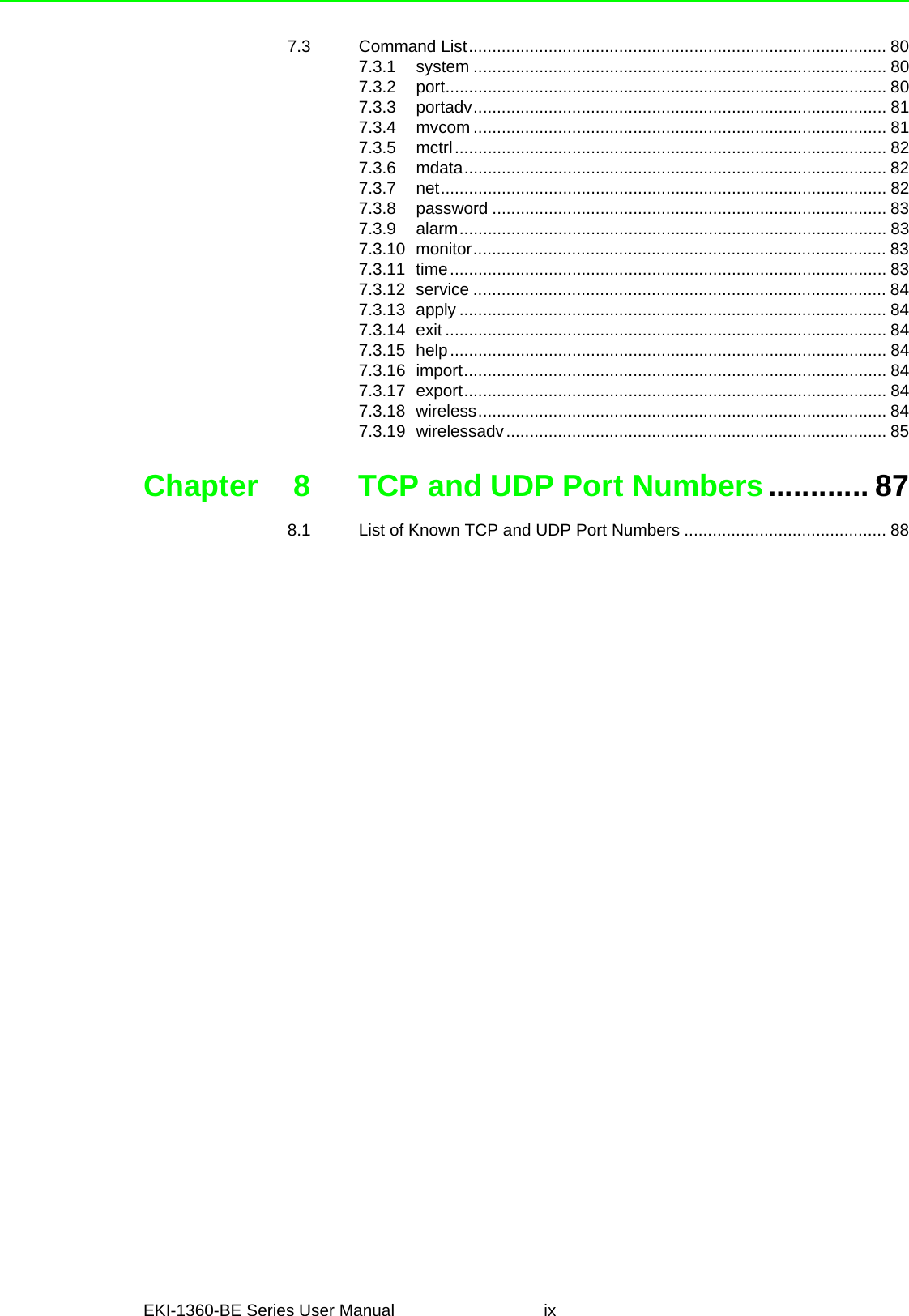
![EKI-1360-BE Series User Manual 807.3 Command List7.3.1 systemUsage: systemShow firmware version, device name and description.Usage: system name [Maximum length 31 bytes]Set current device name.Usage: system desc [Maximum length 127 bytes]Set current device description.7.3.2 portUsage: port [nn|all]Show the “nn”th port or all ports information.Usage: port [nn] desc [Maximum length 127 bytes]Set the “nn”th port’s description.Usage: port [nn|all] type [232|422|485] flow [0|1|2|3]Set serial ports’ type and flow control.–flow 0: None.–flow 1: XOn/XOff.–flow 2: RTS/CTS.–flow 3: DTR/DSR.Command Function Descriptionsystem Show or configure the system informationport Show or configure the serial ports informationportadv Show or configure the serial ports advanced settingsmvcom Show or configure the serial ports in Virtual COM modemctrl Show or configure the serial ports in Control mode (USDG)mdata Show or configure the serial ports in Data mode (USDG)net Show or configure the Ethernet ports settingspassword Set or change the passwordalarm Show or configure the auto warning functions including mail alarm and SNMP alarmmonitor Monitor the serial ports statustime Show or configure the time informationservice Enable or disable the web, Telnet and SNMP functionsapply Write settings to the flash memory and reboot the system immediatelyexit Terminate the shell sessionhelp Display command list help informationimport Import the serial device server all settingsexport Export the serial device server all settingswireless Show or configure the wireless settings or informationswirelessadv Show or configure the advanced wireless settings or informations](https://usermanual.wiki/Advantech-Co/EKI1362BE/User-Guide-4020599-Page-92.png)
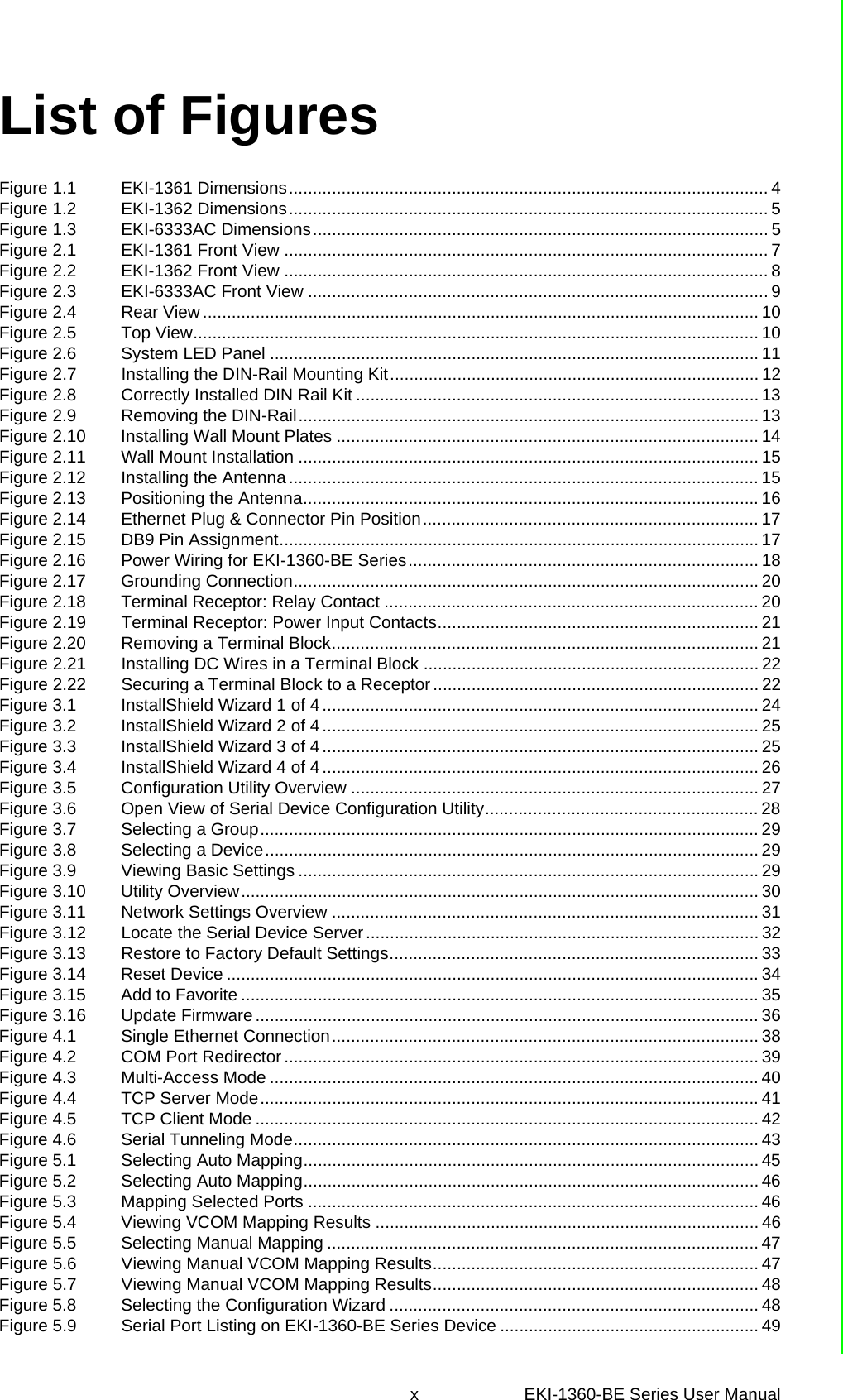
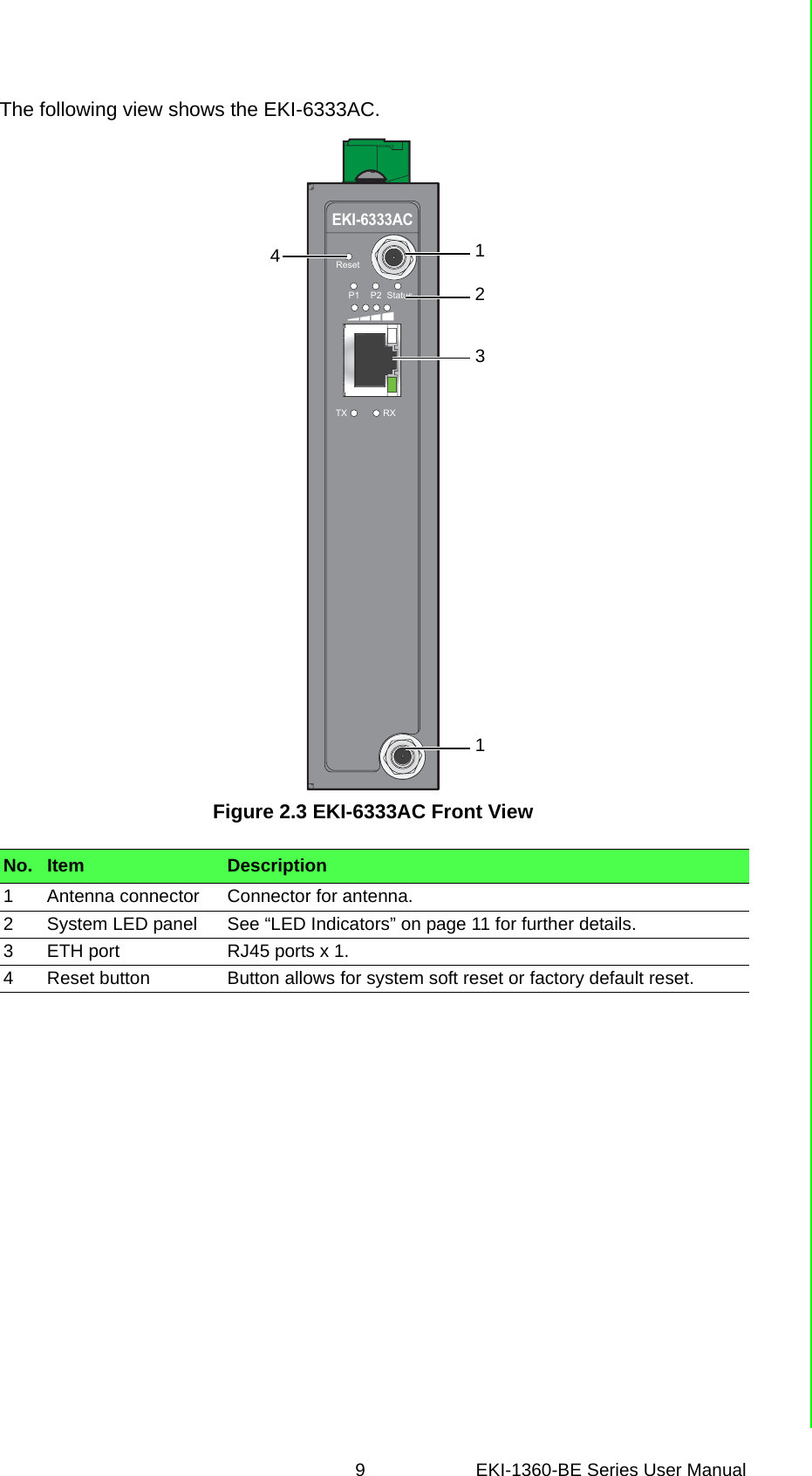
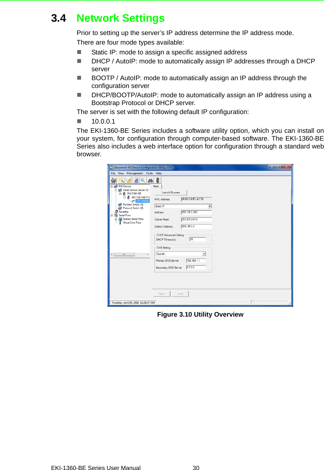
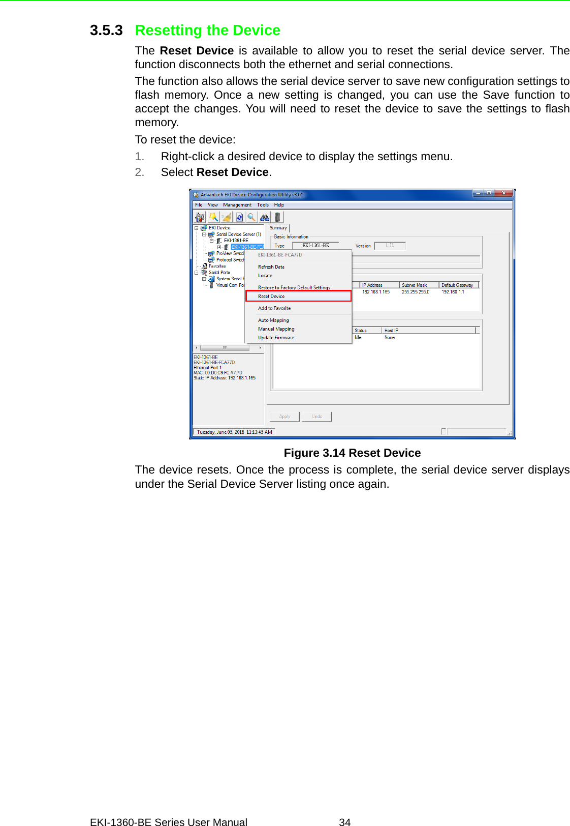
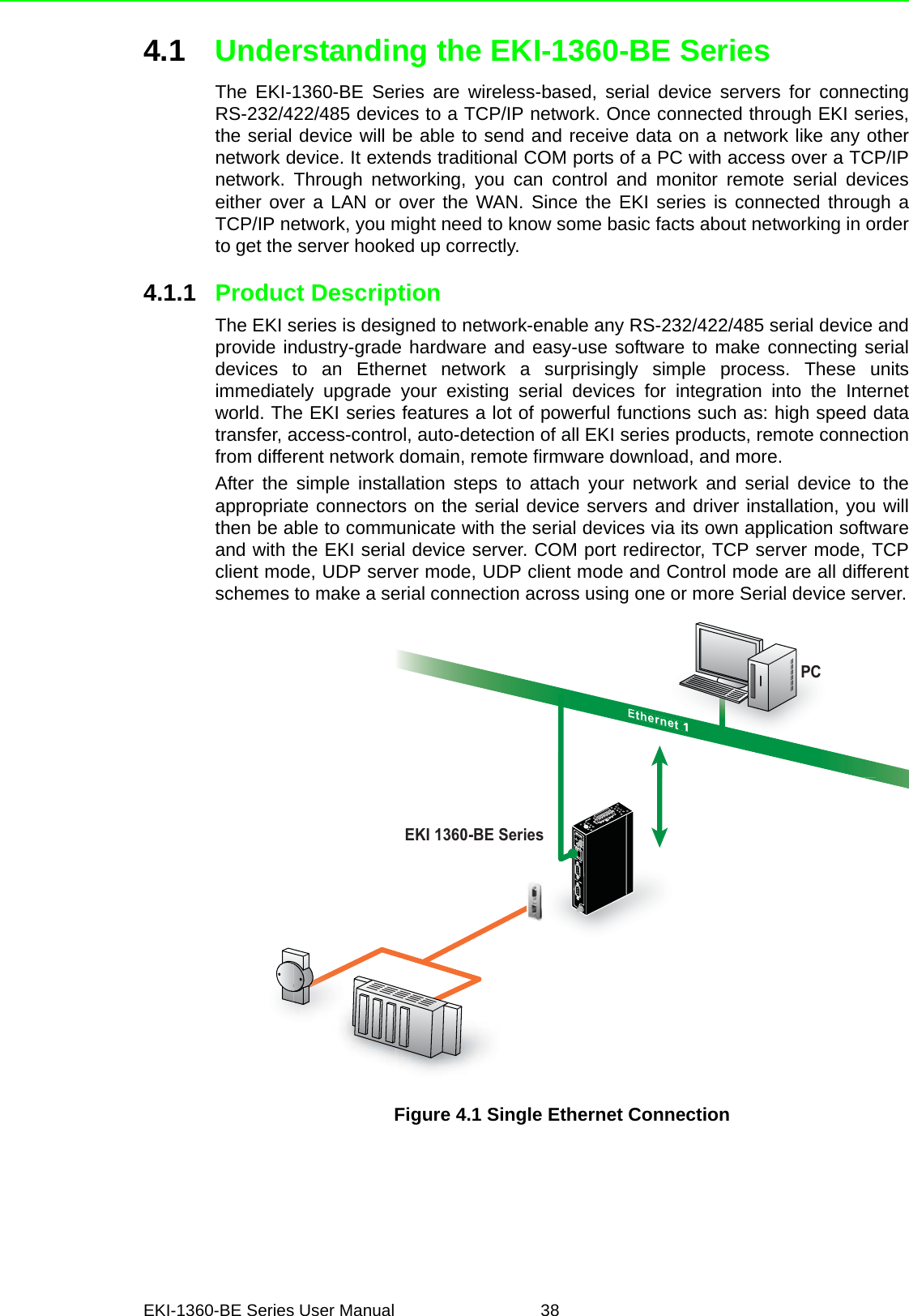
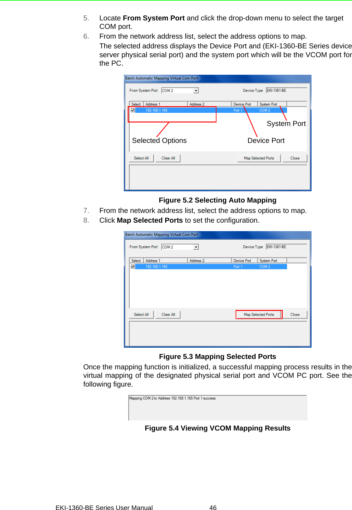
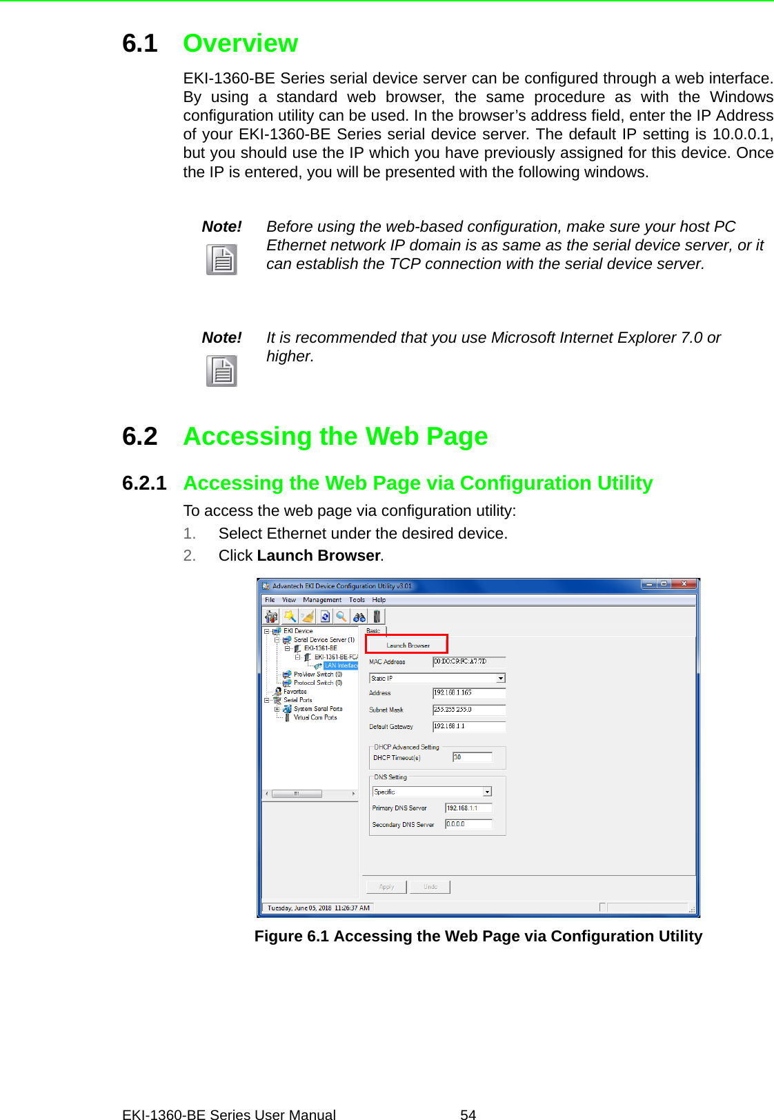
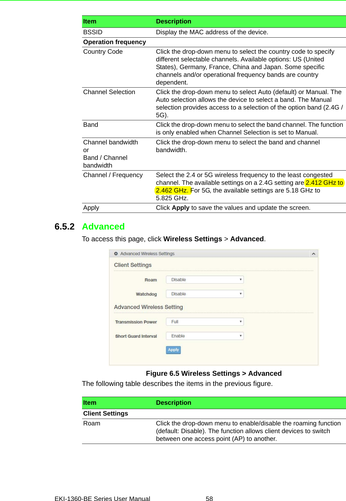
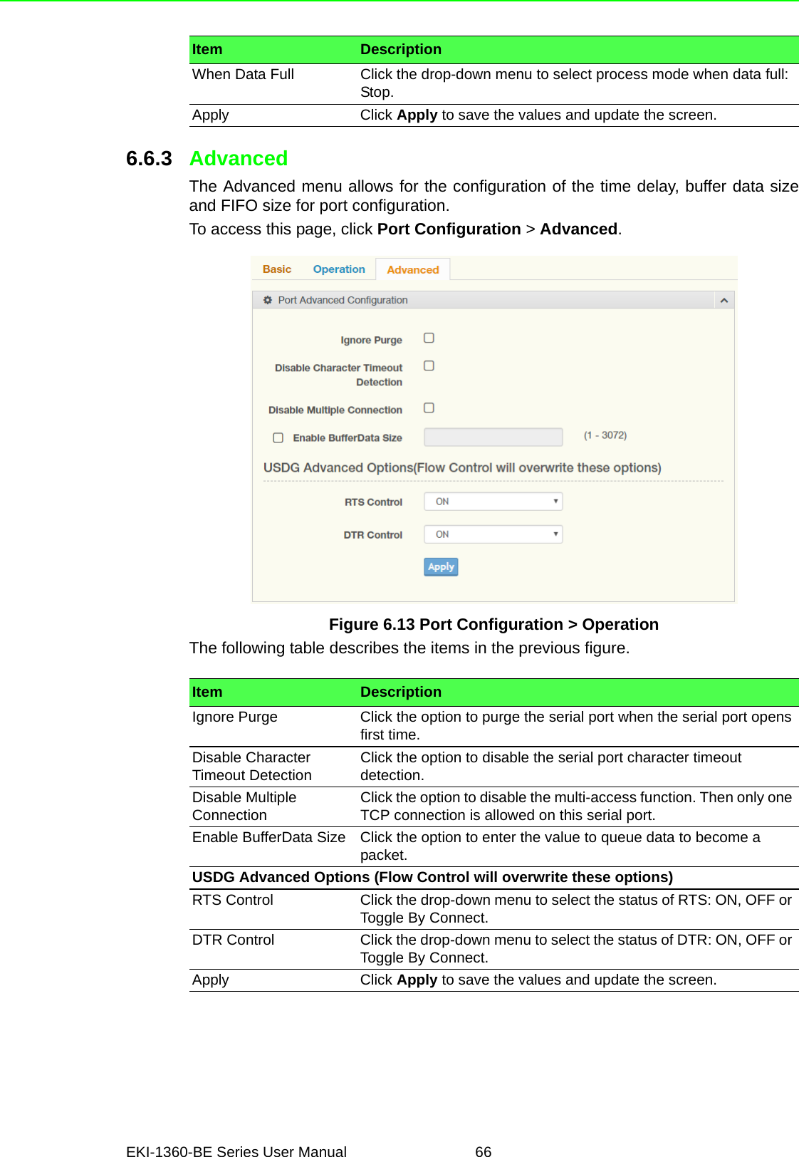
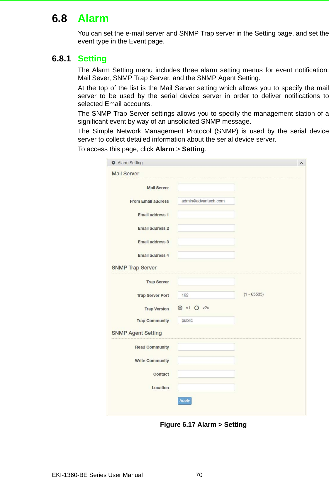
![81 EKI-1360-BE Series User Manual Usage: port [nn|all] baud [50-921600] parity [n|e|o|m|s] data [5-8] stop [1|1.5|2]Set the serial ports’ baud rate, parity, data bits, and stop bits.Acceptable baud: 50, 75, 110, 150, 300, 600, 1200, 1800, 2400, 4800, 7200,9600, 14400, 19200, 38400, 57600, 115200, 230400, 460800, and 921600–parity n: None Parity.–parity e: Even Parity.–parity o: Odd Parity.–parity m: Mark Parity.–parity s: Space Parity.Usage: port [nn|all] mode [vcom|ctrl|data]Set the serial ports as virtual COM mode, control mode, or data mode.7.3.3 portadv$ help portadvShow port advanced setting.Usage: portadv [nn|all] delayT []Set delay time(ms).Usage: portadv [nn|all] ignorepurge [TRUE|FALSE] dischato [TRUE|FALSE]dismulticon [TRUE|FALSE]Enable or disable the feature of ignore purge,Disable character timeout detection, and disable multiple connection.Usage: portadv [nn|all] databuf []Set databuffer threshold.Usage: portadv [nn|all] timeout [] rtl [] ttl [] fcl [] fch []Set port timeout, and set portrtl, portttl, portfcl, portfch.Usage: portadv [nn|all] fifosize [size|null]Set port Writed size of FIFO, null for disableUsage: portadv [nn|all] rts []Set port RTS status.–value 0: None Setting.–value 1: Setting power on.–value 2: Setting accept on.–value 4: Setting transmission on.Usage: portadv [nn|all] dtr []Set port DTR status.–value 0: None Setting.–value 1: Setting power on.–value 2: Setting accept on.–value 4: Setting transmission on.7.3.4 mvcomUsage: mvcomShow all serial ports mode and related information.Usage: mvcom [nn|all]Set the “nn”th or all serial ports as the Virtual COM mode.](https://usermanual.wiki/Advantech-Co/EKI1362BE/User-Guide-4020599-Page-93.png)
![EKI-1360-BE Series User Manual 82Usage: mvcom [nn|all] idleto []Set the “nn”th or all serial ports host idle timeout(S).Usage: mvcom [nn|all] respto [] framebk []Set the “nn”th or all serial ports response timeout and frame break.7.3.5 mctrlUsage: mctrlShow all serial ports mode and related information.Usage: mctrl [nn|all]Set the “nn”th or all serial ports as the control mode.Usage: mctrl [nn|all] idleto [] guardt [] hangchr []Set the “nn”th or all serial ports data idle timeout, guard time and hang character.7.3.6 mdataUsage: mdataShow all serial ports mode and related information.Usage: mdata [nn|all]Set the “nn”th or all serial ports as the data mode.Usage: mdata [nn|all] protocol [TCP|UDP]Set the “nn”th or all serial ports’ transmit protocol as TCP or UDP.Usage: mdata [nn|all] idleto [] lsport [] atport []Set the “nn”th or all serial ports data idle timeout, listen port, and AT commandport.Usage: mdata [nn|all] respto [] framebk []Set the “nn”th or all serial ports response timeout and frame break.Usage: mdata [nn|all] peernum [1-16] peer [d.d.d.d:d] ...Set the peer IP address and port for receive data.7.3.7 netUsage: net [1|2]Show the first or second Ethernet port status and information.Usage: net [1|2] mode [static|dhcp|boot|all]Set the network operating mode.Usage: net [1|2] ip [d.d.d.d] netmask [d.d.d.d] gw [d.d.d.d]Set IP address, subnet mask, and default gateway.Usage: net [1|2] dns [auto|specific]Enable/Disable DNS.Usage: net [1|2] dns1 [d.d.d.d]Set network DNS1.Usage: net [1|2] dns2 [d.d.d.d]Set network DNS2.](https://usermanual.wiki/Advantech-Co/EKI1362BE/User-Guide-4020599-Page-94.png)
![83 EKI-1360-BE Series User Manual 7.3.8 passwordUsage: passwordDisplay two different Usage.Usage: password new [1-31 characters]Set new password.Usage: password old [**...] new [1-31 characters]Confirm the old password and set new password.7.3.9 alarmUsage: alarmShow current alarm informations.Usage: alarm mail server [null|address] from [null|address] to1 [null|address] to2[null|address] to3 [null|address] to4 [null|address]Set current mail server configuration.Usage: alarm trap server [null|address] ver [1|2] community [null|name]Set current trap server configuration.Usage: alarm agent rcommunity [null|name] wcommunity [null|name] contact[null|name] location [null|name]Set current snmp agent configuration.Usage: alarm event mail [cstart] [wstart] [auth] [ip] [passwd] [eth1] [eth2]Set current mail event configuration.Usage: alarm event trap [cstart] [wstart] [auth] [eth1] [eth2]Set current trap event configuration.Usage: alarm port [1|2|..] dcd [none|mail|trap|all] dsr [none|mail|trap|all]Set current port alarm configuration.7.3.10 monitorUsage: monitor port [1-16] settingMonitor the serial ports settings.Usage: monitor port [1-16] statisticMonitor the serial ports statistic.Usage: monitor port [1-16] ipMonitor the serial ports connected IP address.7.3.11 timeUsage: timeShow current time informations.Usage: time [YYYYMMDDhhmmss]Set current time configuration.Usage: time timezone[-12|...|0|1..|12]Set current time zone configuration.Usage: time daylight [on|off] [begin [MMDD] end [MMDD]]Set current daylight saving configuration.Usage: time ntp [timeserver]Set current time server configuration.](https://usermanual.wiki/Advantech-Co/EKI1362BE/User-Guide-4020599-Page-95.png)
![EKI-1360-BE Series User Manual 847.3.12 serviceUsage: service web [enable|disable]Enable/Disable web function.Usage: service telnet [enable|disable]Enable/Disable telnet function.Usage: service snmp [enable|disable]Enable/Disable SNMP function.7.3.13 applyUsage: applySave the settings to the flash memory and reboot the system immediately.7.3.14 exitUsage: exitTerminate the shell session.7.3.15 helpUsage: helpDisplay help information of command list.Usage: help [cmd]Show the usage of command.7.3.16 importUsage: importImport the serial device server settings’ file.7.3.17 exportUsage: exportExport the serial device server settings’ file.7.3.18 wirelessUsage: wirelessShow or configure the wireless settings or informations.Usage: wireless ssid []Set SSID.Usage: wireless country [us|de|fr|es|jp|kr|cn] channel [0|1|…|14]Set country code and channel.–us: United States–de: Germany–fr: France–es: Spain–jp: Japan–kr: Korea–cn: China–channel 0: Auto](https://usermanual.wiki/Advantech-Co/EKI1362BE/User-Guide-4020599-Page-96.png)
![85 EKI-1360-BE Series User Manual Usage: wireless encryption [none|wep|wpa-psk|wpa-enterprise]Set encryption type.Usage: wireless wepauth [on|off]Set WEP authentication algorithm.Usage: wireless wepidx [0|1|2|3]Set WEP key index.Usage: wireless wepkey [asc|hex] []Set WEP key as [] in specific format.Usage: wireless wpakey []Set WPA-PSK key as [].Usage: wireless wpaeap [tls|ttls|peap]Set WPA-Enterprise EAP method.Usage: wirelesswpa11w [0|1|2]Set WPA-Enterprise management frame protected.–0: Disable–1: Optional–2: RequiredUsage: wireless wpaid []Set WPA-Enterprise identity as [].Usage: wireless wpapw []Set WPA-Enterprise as [].Usage: wireless wpaphase [mschapv2|md5]Set WPA-Enterprise inner authentication.Usage: wireless capw []Set private key as [].Usage: wireless cacertImport the CA certification from host PC to device.Usage: wireless caclientImport the Client certification from host PC to device.Usage: wireless cakeyImport the private key from host PC to device.7.3.19 wirelessadvUsage: wirelessadvShow device wireless advance informations.Usage: wirelessadv rts [256|…|2347]Set RTS threshold.Usage: wirelessadv frag [256|…|2346]Set fragmentation threshold.Usage: wirelessadv roaming [on|off]Enable/disable Roaming.Usage: wirelessadv rssi [10|…|95]Set connection quality monitor RSSI threshold.Usage: wirelessadv preamble [short|long]Set preamble.](https://usermanual.wiki/Advantech-Co/EKI1362BE/User-Guide-4020599-Page-97.png)
![EKI-1360-BE Series User Manual 86Usage: wirelessadv scanint_high [10|…|600]Set scan interval when received signal strength is better than RSSI threshold.Usage: wirelessadv scanint_low [10|…|600]Set scan interval when received signal strength is worse than RSSI threshold.](https://usermanual.wiki/Advantech-Co/EKI1362BE/User-Guide-4020599-Page-98.png)