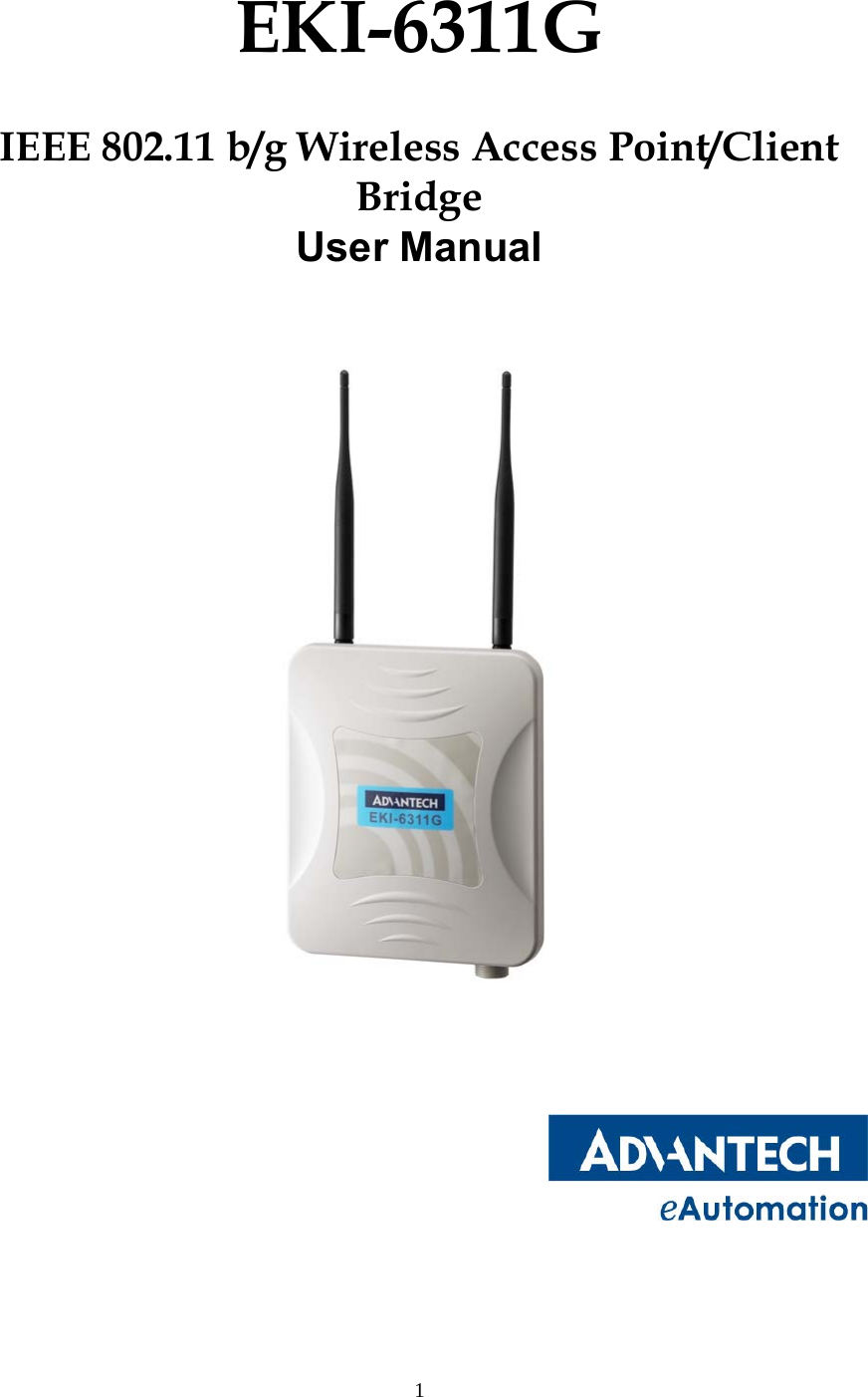
Advantech Co EKI6311G IEEE 802.11b/g Wireless Access Point/Client Bridge User Manual Quick install
Advantech Co Ltd IEEE 802.11b/g Wireless Access Point/Client Bridge Quick install
UserManual.wiki
>
Advantech Co
>
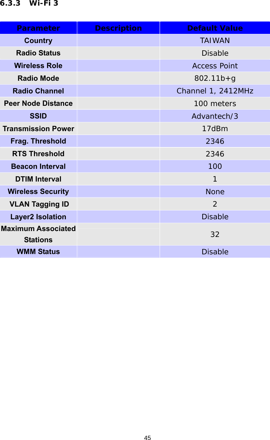
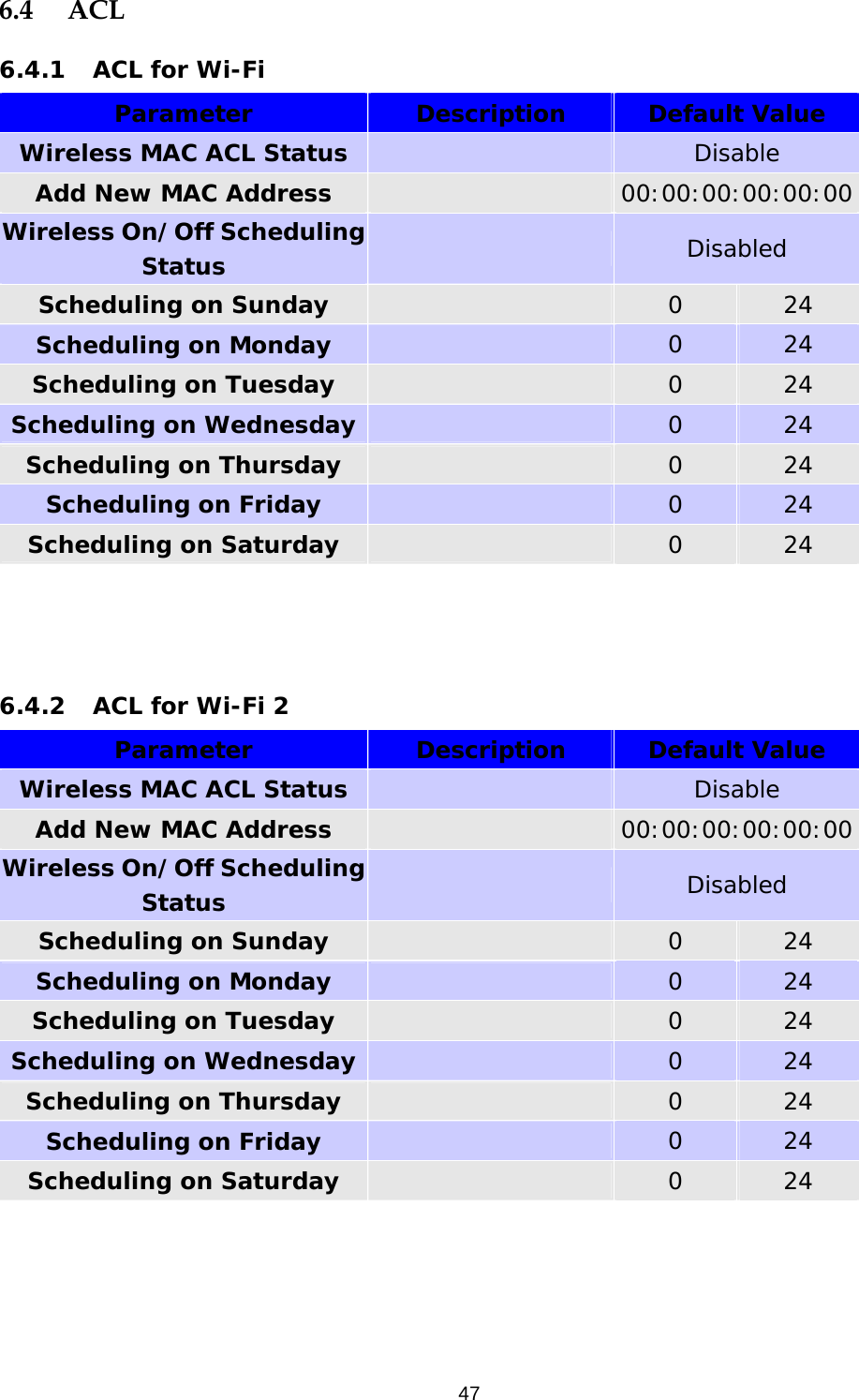
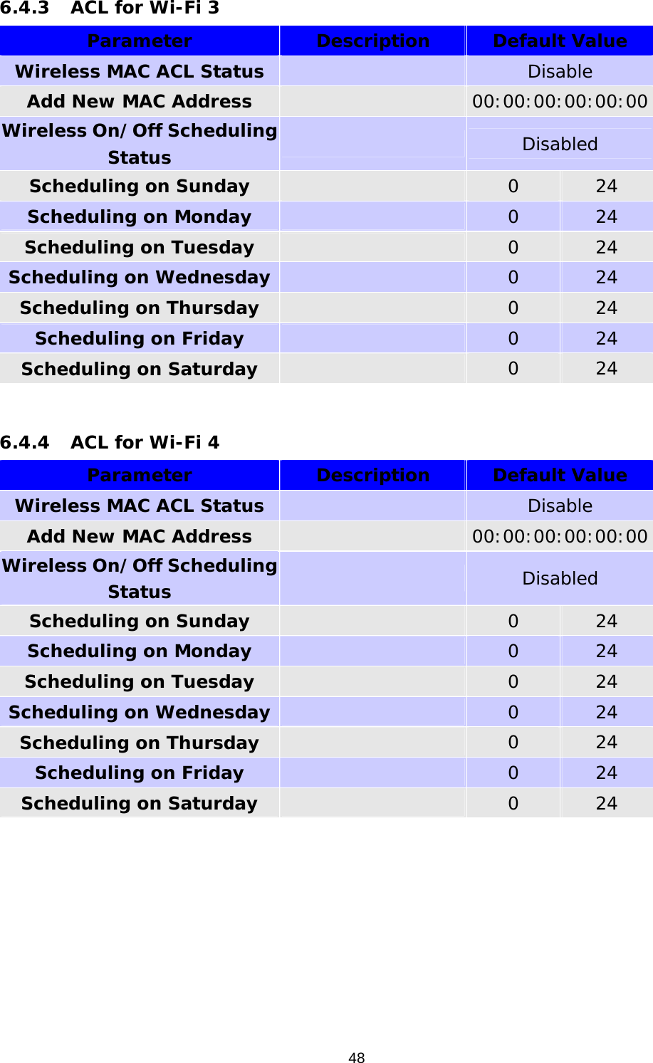
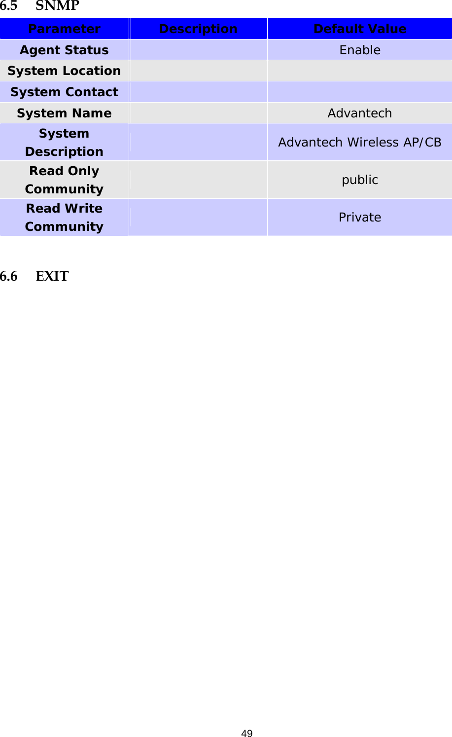
EKI6311G User Manual
User manual
Navigation menu
Upload a User Manual
Namespaces
Wiki Guide
HTML
PDF
Info
Views
User Manual
Discussion / Help
Navigation