Advantech Co EKI6323AG WLAN 802.11a/b/g mini-PCI Module User Manual CM9 G Manual 0604
Advantech Co Ltd WLAN 802.11a/b/g mini-PCI Module CM9 G Manual 0604
UserManual.wiki
>
Advantech Co
>
EKI6323AG User Manual
User manual
Navigation menu
Upload a User Manual
Namespaces
Wiki Guide
HTML
PDF
Info
Views
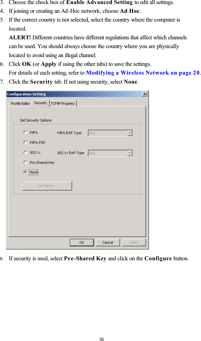
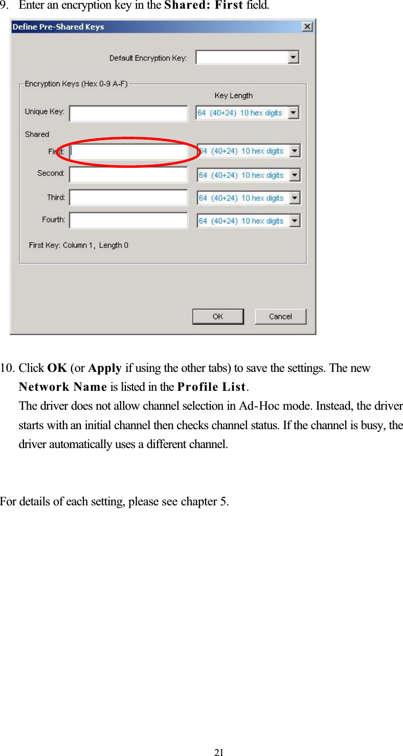
User Manual
Discussion / Help
Navigation