Advantech Co IVU4000 Computer User Manual
Advantech Co Ltd Computer
Contents
- 1. User Manual
- 2. Users Manual
- 3. Manual
User Manual

Us
e
e
r M
a
a
nu
a
a
l
I
V
C
o
m
V
U-4
o
mpu
t
anage
m
4
000
t
ing B
m
ent
&
ox for
&
surv
e
Fleet
e
illanc
e
e

IVU4000 User Manual 2
Copyright
The documentation and the software included with this product are copyrighted 2016
by Xerox Co., Ltd. All rights are reserved. Xerox Co., Ltd. reserves the right to make
improvements in the products described in this manual at any time without notice.
No part of this manual may be reproduced, copied, translated or transmitted in any
form or by any means without the prior written permission of Xerox Co., Ltd.
Information provided in this manual is intended to be accurate and reliable. How- ever,
Xerox Co., Ltd. assumes no responsibility for its use, nor for any infringe- ments of
the rights of third parties, which may result from its use.
Acknowledgements
Intel® and Atom are trademarks of Intel Corporation.
Microsoft Windows® is registered trademarks of Microsoft Corp.
All
other product
names or trademarks are properties of their respective owners.
Product Warranty (2 year)
Xerox warrants to you, the original purchaser, that each of its products will be free
from defects in materials and workmanship for two years from the date of pur-
chase.
This warranty does not apply to any products which have been repaired or altered by
persons other than repair personnel authorized by Xerox, or which have been
subject to misuse, abuse, accident or improper installation. Xerox assumes no
liability under the terms of this warranty as a consequence of such events.
Because of Xerox’s high quality-control standards and rigorous testing, most of our
customers never need to use our repair service. If an Xerox product is defec tive, it will
be repaired or replaced at no charge during the warranty period. For out- of-warranty
repairs, you will be billed according to the cost of replacement materials, service time
and freight. Please consult your dealer for more details.
If you think you have a defective product, follow these steps:
1. Collect all the information about the problem encountered. (For example, CPU
speed, Xerox products used, other hardware and software used, etc.) Note
anything abnormal and list any onscreen messages you get when the problem
occurs.
2. Call your dealer and describe the problem. Please have your manual, product,
and any helpful information readily available.
3. If your product is diagnosed as defective, obtain an RMA (return merchandize
authorization) number from your dealer. This allows us to process your return
more quickly.
4. Carefully pack the defective product, a
fully-completed
Repair and Replacement
Order Card and a photocopy proof of purchase date (such as your sales receipt)
in a shippable container. A product returned without proof of the purchase date
is not eligible for warranty service.
5. Write the RMA number visibly on the outside of the package and ship it prepaid
to your dealer.
Part No. Edition 1
Printed in Taiwan June. 2016

3 IVU4000 User Manual
Declaration of Conformity
For FCC Class A digital device or peripheral
This equipment has been tested and found to comply with the limits for a Class A digital device,
pursuant to part 15 of the FCC Rules. These limits are designed to provide reasonable protection
against harmful interference when the equipment is operated in a commercial environment. This
equipment generates, uses, and can radiate radio frequency energy and, if not installed and used in
accordance with the instruction manual, may cause harmful interference to radio communications.
Operation of this equipment in a residential area is likely to cause harmful interference in which case
the user will be required to correct the interference at his own expense.
Any changes or modifications not expressly approved by the party responsible for
compliance could void the authority to operate equipment.
This device and its antenna must not be co-located or operating in conjunction with any
other antenna or transmitter.
FCC RF Radiation Exposure Statement
This equipment complies with FCC radiation exposure limits set forth for an uncontrolled environment.
This equipment should be installed and operated with minimum distance 20cm between the radiator
& your body.
For IC
This device complies with Industry Canada’s licence-exempt RSSs. Operation is subject to the
following two conditions: (1) This device may not cause interference; and (2) This device must accept
any interference, including interference that may cause undesired operation of the device.
Le présent appareil est conforme aux CNR d'Industrie Canada applicables aux appareils radio
exempts de licence. L'exploitation est autorisée aux deux conditions suivantes : (1) l'appareil ne doit
pas produire de brouillage, et (2) l'utilisateur de l'appareil doit accepter tout brouillage radioélectrique
subi, même si le brouillage est susceptible d'en compromettre le fonctionnement.
For RSS-247 6.4(5) WLAN 11a
(i)the device for operation in the band 5150–5250 MHz is only for indoor use to reduce the potential
for harmful interference to co-channel mobile satellite systems;
(ii) for devices with detachable antenna(s), the maximum antenna gain permitted for devices in the
bands 5250-5350 MHz and 5470-5725 MHz shall be such that the equipment still complies with the
e.i.r.p. limit;
(iii) for devices with detachable antenna(s), the maximum antenna gain permitted for devices in the
band 5725-5850 MHz shall be such that the equipment still complies with the e.i.r.p. limits specified
for point-to-point and non-point-to-point operation as appropriate; and
(iv) the worst-case tilt angle(s) necessary to remain compliant with the e.i.r.p. elevation mask
requirement set forth in Section 6.2.2(3) shall be clearly indicated.
Users should also be advised that high-power radars are allocated as primary users (i.e. priority users)
of the bands 5250-5350 MHz and 5650-5850 MHz and that these radars could cause interference
and/or damage to LE-LAN devices.
(i) l'appareil pour fonctionner dans la bande 5150-5250 MHz est réservé à une utilisation en intérieur
afin de réduire les risques d'interférences nuisibles à la co-canal systèmes mobiles par satellite;

IVU4000 User Manual 4
(ii) pour les appareils avec antenne (s) détachable, le gain d'antenne maximal autorisé pour les
appareils dans les bandes 5250-5350 MHz et 5470-5725 MHz doit être telle que l'équipement
satisfait encore la pire limite;
(iii) pour les appareils avec antenne (s) détachable, le gain d'antenne maximal autorisé pour les
appareils dans la bande 5725-5850 MHz doit être telle que l'équipement satisfait encore la pire limites
spécifiées pour le point-à-point et non point-à-point, le cas échéant; opération et
(iv) l'angle d'inclinaison du pire (s) nécessaire pour rester conforme à la pire exigence de masque
d'élévation énoncées dans la section 6.2.2 (3) doit être clairement indiqué.
Devraient également être informés les utilisateurs que les radars à haute puissance sont désignés
comme utilisateurs principaux (c.-à-utilisateurs prioritaires) des bandes 5250-5350 MHz et 5650-5850
MHz et que ces radars pourraient provoquer des interférences et / ou endommager les appareils LE-
LAN.
ICRadiationExposureStatement:
This equipment complies with IC RSS-102 radiation exposure limits set forth for an uncontrolled
environment. This equipment should be installed and operated with minimum distance 20cm between
the radiator & your body.
Technical Support and Assistance
1. Visit the Xerox web site at http://support.Xerox.com
where you can find the latest
information about the product.
2. Contact your distributor, sales representative, or Xerox's customer service
center for technical support if you need additional assistance. Please have the
following information ready before you call:
– Product name and serial number
– Description of your peripheral attachments
– Description of your software (operating system, version, application software,
etc.)
– A complete description of the problem
– The exact wording of any error messages

W
a
D
o
Pa
a
rning
s
Warn
i
n
Cauti
o
Not
e
o
cume
n
To ass
i
and c
o
tech.c
o
cking
L
Before
good c
o
immed
i
Partnu
m
410000
410001
Tobeu
s
, Cau
t
i
n
g! Warni
n
injury!
o
n! Cauti
o
data.
e
There
Do no
batter
y
ufact
u
instru
c
e!
Notes
n
t Fee
d
i
st us in m
a
o
nstructive
o
m
L
ist
setting up
o
ndition. If
i
ately.
m
ber
‐AAAAAX
pdate
t
ions a
n
n
gs indicat
e
o
ns are incl
u
e
.g.
is a dange
r
t
attempt to
y
only with
t
u
rer. Discar
d
c
tions.
provide o
pt
d
back
a
king impr
o
criticism.
P
the syste
m
a
ny item d
o
Descripti
o
IVUMP
u
Cfast,1x
W
MDTDisp
l
MDTCabl
e
5
n
d No
t
e
condition
s
u
ded to hel
p
r
of a new
b
recharge,
f
t
he same o
r
d
used batt
e
t
ional addit
i
o
vements t
o
P
lease sen
d
m
, check th
a
o
es not acc
o
n
u
nit,16GB
W
iFi,1x4G,
B
layMPunit
e
t
es
s
, which if n
o
p
you avoi
d
b
attery expl
o
f
orce open,
r
equivalen
t
e
ries accor
d
i
onal infor
m
o
this man
u
d
all such
a
t the item
s
ord with th
e
mSATA,4G
B
B
aytrail
IVU4000
U
o
t observed
,
damaging
h
o
ding if it is
or heat the
type reco
m
d
ing to the
m
ation.
al, we wou
- in writin
g
s
listed bel
o
e
table, ple
a
Q`ty
B
1
1
1
U
ser Manual
d
, can caus
e
hardware
o
incorrectly
battery. R
e
m
mended b
y
m
anufactur
e
u
ld welcom
e
g to: sup
p
o
w are incl
u
a
se contact
e
personal
o
r losing
installed.
e
place the
y
the man-
e
r's
e
comment
s
ort@advan
u
ded and i
n
your deale
s
-
n
r

IVU4000 User Manual 6
Ordering Information
P/NDesc
r
iption
410000-AAAAAXAtomE3827/LTE/GPS/WLAN/WE8S32bit
410000‐AAAXAXAtomE3827/GPS/WLAN/WE8S32bit
410000‐AABAAX AtomE3827/LTE/GPS/WLAN*2/WE8S32bit
Safety Instructions
1. Read these safety instructions carefully.
2. Keep this User Manual for later reference.
3. Disconnect this equipment from any AC outlet before cleaning. Use a damp
cloth. Do not use liquid or spray detergents for cleaning.
4. For plug-in equipment, the power outlet socket must be located near the equip-
ment and must be easily accessible.
5. Keep this equipment away from humidity.
6. Put this equipment on a reliable surface during installation. Dropping it or
letting
it
fall may cause damage.
7. Do not leave this equipment in an environment unconditioned where the storage
temperature under -40° C (-40° F) or above 80° C (176° F), it may damage the
equipment. Operating temperature: -30° C ~65° C.
8. The openings on the enclosure are for air convection. Protect the equipment
from overheating. DO NOT COVER THE OPENINGS.
9. Make sure the voltage of the power source is correct before connecting the
equipment to the power outlet.
10. Position the power cord so that people cannot step on it. Do not place anything
over the power cord. The voltage and current rating of the cord should be greater
than the voltage and current rating marked on the product.
11. All cautions and warnings on the equipment should be noted.
12. If the equipment is not used for a long time, disconnect it from the power source
to avoid damage by transient overvoltage.
13. Never pour any liquid into an opening. This may cause fire or electrical shock.
14. Never open the equipment. For safety reasons, the equipment should be
opened only by qualified service personnel.
15. If one of the following situations arises, get the equipment checked by service
personnel:
The power cord or plug is damaged.
Liquid has penetrated into the equipment.
The equipment has been exposed to moisture.
The equipment does not work well, or you cannot get it to work according to
the user's manual.
The equipment has been dropped and damaged.
The equipment has obvious signs of breakage.
16. CAUTION: The computer is provided with a battery-powered real-time clock cir-
cuit. There is a danger of explosion if battery is incorrectly replaced. Replace
IVU4000 User M
a
o
n
u
s
17. T
H
P
R
18. T
h
fo
(1
(2
19. C
A
w
h
p
o
p
o
20. C
A
th
v
e
w
r
s
u
21. C
A
e
n
p
r
22. C
a
23. "
R
in
c
A)
B
)
C
)
D
)
a
nual
n
ly with sa
m
s
ed batterie
H
E COMP
U
R
IATE SAF
h
is device
c
llowing two
) this devic
e
) this devic
e
may cau
s
A
UTION:
Al
h
enever yo
u
o
we
r
is on.
S
o
we
r
surge
s
A
UTION:
Al
e motherb
o
e
ry sensitiv
e
r
ist strap at
u
rface or in
A
UTION:
An
n
sure the c
o
r
ovided wit
h
a
ution text
c
R
ack Mount
c
luded with
)
Elevated
assembly
be great
e
installing
ambient t
e
)
Reduced
A
the amo
u
comprom
)
Mechanic
a
that a ha
z
ing.
)
Circuit O
v
equipme
n
might ha
v
m
e or equiv
a
s accordin
g
U
TER IS P
R
ETY ST
A
N
D
c
omplies wi
t
conditions:
e
may not
c
e
must acc
e
e undesire
d
l
ways com
p
u
work with
S
ensitive el
s
.
l
ways grou
n
o
ard, backpl
e
to static el
all times.
P
a static-shi
e
n
y unverifi
e
o
rrect instal
h
the acces
s
c
oncerning
Instruction
s
the install
a
Operating
,
the opera
er
than roo
m
the equip
m
e
mperatur
e
A
i
r
Flow - I
n
u
nt of air fl
o
i
sed.
a
l Loading
-
z
ardous co
n
v
erloading -
n
t to the su
p
v
e on over
c
a
lent type r
e
g
to the ma
n
R
OVIDED
W
D
ARDS IN
C
t
h Part 15 o
:
c
ause harm
f
e
pt any int
e
d
operation
.
p
letely disc
o
the hardw
a
l
ectronic co
n
d yourself
t
l
ane, or ad
d
ectric char
g
P
lace all ele
c
e
lded bag
w
e
d compon
e
lation, plea
s
s
ory box.
lithium batt
s
- The foll
o
a
tion instru
c
Ambient
-
a
ting ambie
n
m
ambient.
m
ent in an
e
(Tma) spe
c
n
stallation
o
o
w require
d
- Mounting
n
dition is n
o
Considera
t
p
ply circuit
c
urrent prot
e
6
e
commend
e
n
ufacturers
W
ITH CD D
R
C
LUDING I
E
f
the FCC r
f
ul interfere
e
rference r
e
.
o
nnect the
p
a
re. Do not
mponents
c
t
o remove
a
d
-on cards.
g
es. As a s
a
c
tronic co
m
w
hen they a
e
nt could ca
s
e always
u
e
ries:
o
wing or si
m
c
tions:
-
If installe
n
t tempera
t
Therefore,
environme
c
ified by th
e
of
the equip
m
d
for safe
o
of the equ
i
o
t achieve
d
t
ion should
and the eff
e
e
ction and
s
e
d by the m
instruction
s
R
IVES CO
M
E
C 60825.
u
les. Oper
a
nce, and
e
ceived, inc
l
p
ower cord
f
m
ake conn
e
c
an be dam
a
a
ny static c
h
Modern ele
a
fety preca
u
m
ponents on
re not in th
e
use unexp
e
u
se the com
m
ila
r
rack-m
d
in a clo
s
t
ure of the
considerat
nt compati
b
e
manufact
u
m
ent in a r
a
o
pe
r
ation o
f
pment in t
h
d
due to un
be given t
o
e
ct that ov
e
s
upply wirin
g
m
anufacture
.
s
.
M
PLY WIT
H
a
tion is subj
luding inte
r
f
rom your
c
ections whi
aged by su
h
arge befor
e
e
ctronic dev
u
tion, use a
n
a static-di
s
e
chassis.
e
cted dama
m
ponents (e
x
ount instru
c
sed or m
u
rack envir
o
t
ion should
b
le with th
e
u
rer.
a
ck should
b
f
the equi
p
h
e rack sh
o
even mec
h
o
the conn
e
e
rloading o
f
g
. Appropri
a
.
Discard
H
APPRO-
ect to the
f
e
r
ence th
a
c
hassis
l
e the
d
den
e
touching
ices are
grounding
s
sipative
ge. To
x
. screws)
c
tions are
u
lti-unit rac
k
o
nment ma
y
be given t
o
e
maximu
m
b
e such th
a
p
ment is n
o
o
uld be suc
h
h
anical load
e
ction of th
e
f
the circuit
s
a
te consid-
a
t
k
y
o
m
a
t
o
t
h
-
e
s

Safet
y
F
d
era
t
con
E)
R
mai
dire
24. CA
U
To
a
25. CA
U
Onl
y
per
f
or
d
Foll
dev
Foll
a v
e
y
Prec
a
F
ollow thes
e
d
amage.
To avoi
d
before
y
t
ion of equ
i
cern.
R
eliable E
a
ntained. P
a
ct connecti
o
U
TION :
a
void any p
U
TION :
y
the quali
f
f
orm the in
s
d
amage the
ow the ins
t
ice.
ow the inst
r
e
hicle.
Determin
e
the driver
unit in th
e
driver`s s
e
Connect t
Routing
E
Esta
b
hot s
Fix t
h
but
m
Whe
n
Ens
u
reco
m
Ens
u
DO
N
Ens
u
All
p
inten
tem
p
Do n
turni
n
a
ution
e
simple pr
e
d
electrical
y
ou work o
n
pment na
m
a
rthing - R
e
a
rticula
r
att
e
o
ns to the
b
ossible ac
c
f
ied engine
s
tallation in
vehicle an
d
t
allation as
r
uctions be
l
e
the best l
`
s field of
v
e
car pass
e
at or locat
e
h
e vehicle
c
lectrical C
a
b
lish a nea
urfaces wh
e
h
e cable to
m
ake sure t
h
n
the cabli
n
u
re the c
a
m
mended r
a
u
re cables
d
N
OT wind a
u
re that all f
u
p
ower wirin
ded appli
c
p
erature, ex
CAUTI
O
ot open th
e
n
g off the p
o
- Stati
c
e
cautions t
o
shock, alw
a
n
it. Don't t
o
m
eplate rati
e
liable eart
h
e
ntion shou
b
ranch circ
u
c
ident, plea
s
er by Xero
x
a vehicle.
d
/or IVU40
0
below to a
v
l
ow to prop
e
ocation for
v
iew and e
enger co
m
e
d on cent
e
c
omputer t
o
a
bles
a
r route for
enever po
s
existing c
a
h
ey are aw
a
n
g must go
t
a
ble does
adius is 2.
5
d
o not swin
g
cable in a
n
u
ses install
n
g must u
s
c
ations of
posure an
d
O
N
e
cover on
t
o
wer.
c
Elec
t
o
protect yo
u
a
ys discon
n
o
uch any c
o
ngs should
h
ing of rac
ld be given
u
it (e.g. use
s
e followin
g
x
Transpo
r
Improper i
n
0
0 comput
e
v
oid overlo
a
e
rly install
t
mounting
t
ase of acc
partment.
S
e
r console.)
o
the vehicl
e
the cable,
sible.
a
ble runs in
a
y from an
y
t
hrough a
p
not hav
e
5
”.
g
or chafe
o
n
d out of th
e
ed as instr
u
s
e the su
p
SAE with
d
flammabili
t
t
he front si
d
t
ricity
u
rsel
f
from
n
ect the po
w
o
mponents
o
be used
w
k-mounted
to supply
c
of power s
t
g
instructio
n
t
ation Man
a
n
stallation
c
r system.
a
ding the
c
he IVU400
0
t
he unit ta
k
e
ssing the
S
uggested
e
`s wiring s
y
staying cl
e
side the v
e
y
moving or
p
anel, use
a
e
tight b
e
o
n the struc
t
e
mesh on
a
u
ction. 32
V
p
plied pow
e
suitable
t
y.
d
e as illust
r
h
arm and t
h
w
e
r
from yo
u
o
n the CPU
w
hen addr
e
equipmen
t
c
onnection
s
t
rips)."
n
s to operat
a
gement S
c
an injure t
h
c
ircuit after
0
computin
g
k
ing into c
o
unit. (Onl
y
locations
a
s
ystem as b
e
ar of movi
n
e
hicle using
r
hot surfac
e
a
suitable c
a
e
nds. The
t
ure.
a
cage.
V
olt is suita
b
e
r cable c
o
ratings of
r
ation as b
e
h
e product
s
ur
PC chas
s
U
card or ot
h
e
ssing this
t
should b
e
s
other than
e
this unit.
olution can
h
e operato
r
adding thi
s
g
system in
o
nsideration
install thi
s
a
re next t
o
elow.
n
g parts o
r
cable ties,
e
s.
a
ble gland.
minimum
b
le for unit.
o
mply with
electrical,
e
low befor
e
s
from
s
is
h
er
e
r
s
s
o
r
e

IVU4
000 User M
a
cards
w
Discon
n
of pow
e
tronic
c
This pr
o
9~32V
d
purcha
s
Manag
e
Warning!
1
2
3
4
a
nual
w
hile the P
C
n
ect power
er
as you c
o
c
omponent
s
o
duct is int
e
d
c, 10
A
mi
n
s
ing the D
C
e
ment Sol
u
1
. Input
v
2
. Trans
p
3
. Maint
e
appro
v
4
. Comp
a
Comp
a
C
is on.
before ma
k
o
nnect a
j
u
m
s
.
e
nded to b
e
n
imum and
T
C
power so
u
tion for fur
t
v
oltage rate
d
p
ort: carry t
h
e
nance: to
p
v
ed produc
t
a
ctFlash: T
u
a
ctFlash st
o
k
ing any co
n
m
pe
r
or ins
t
e
supplied
b
T
ma 65 de
g
u
rce, pleas
e
r
ther inform
a
d: 9 ~ 32 V
d
h
e unit with
p
roperly ma
i
t
s or clean
w
u
rn off the
p
o
rage card
s
8
n
figuration
c
t
all a card
m
b
y a Listed
D
g
ree C, if n
e
e
contact
X
a
tion.
d
c.
both hand
s
i
ntain and c
l
w
ith a dry a
p
p
ower befo
r
s
.
c
hanges. T
h
m
ay damag
e
D
C power
s
e
ed further
X
erox Trans
s
and handl
e
l
ean the su
r
p
plicator.
e
inserting
o
h
e sudden
r
e
sensitive
e
s
ource, rat
e
assistance
portation
e
with care
.
r
faces, use
o
r removin
g
r
ush
e
lec-
e
d
with
only
g

Contents
Chapter 1 General Information ............................1
1.1 Introduction
...............................................................................................
2
1.2 General
Specifications ..............................................................................
3
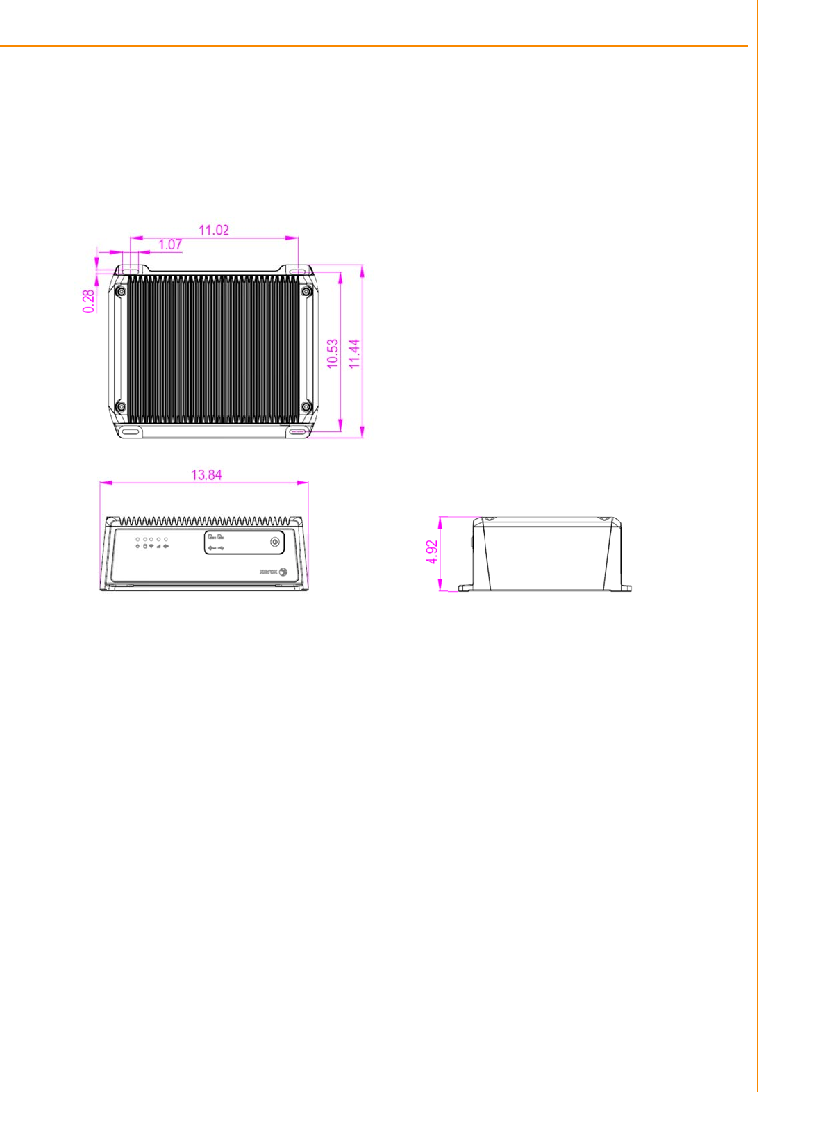
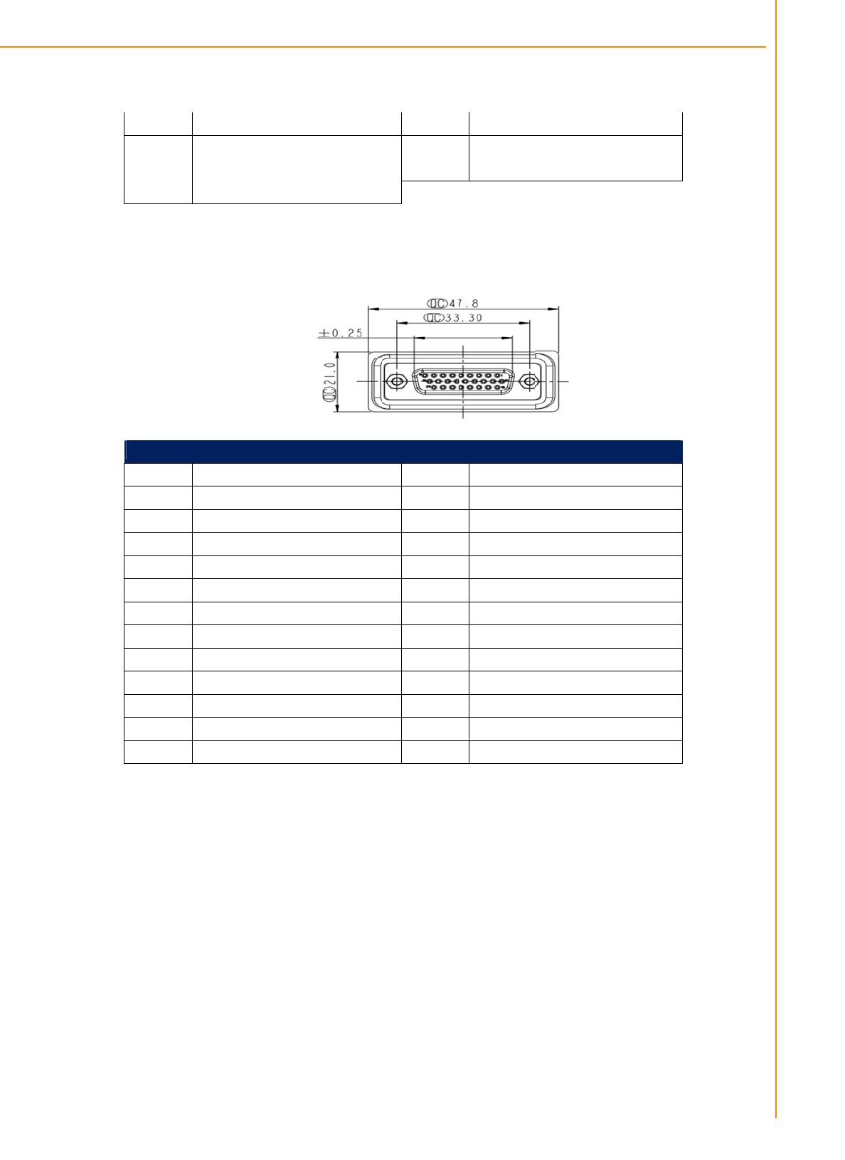
1.3 Dimensions
...............................................................................................
5
Figure 1.1 IVU-4000
dimensions................................................
5
Chapter
2 System
Setup
.......................................7
2.1
2.2
A Quick Tour of the IVU4000 Computing
Box
........................................
8
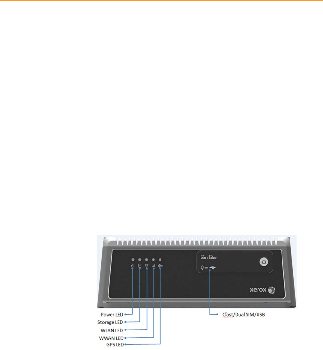
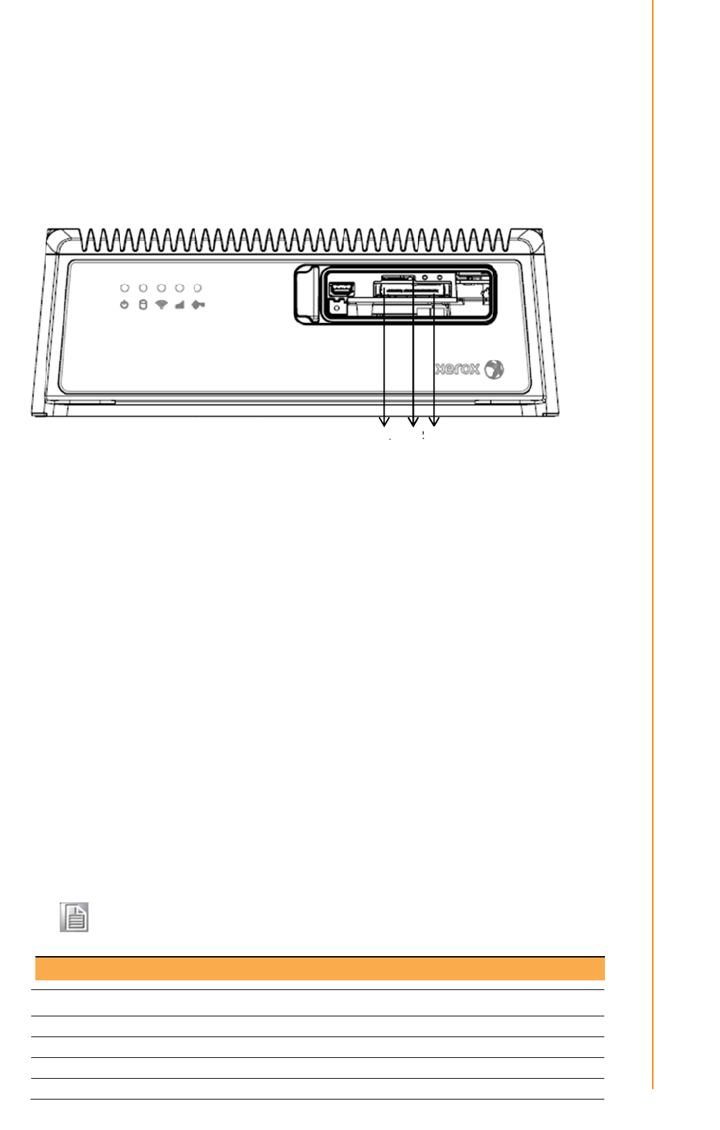
Figure 2.1 Front view of
IVU4000 .............................................
8
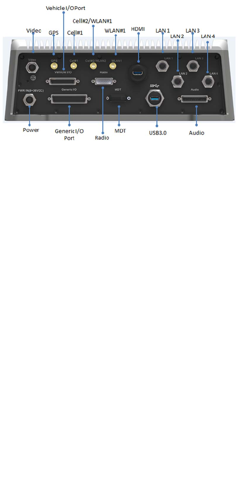
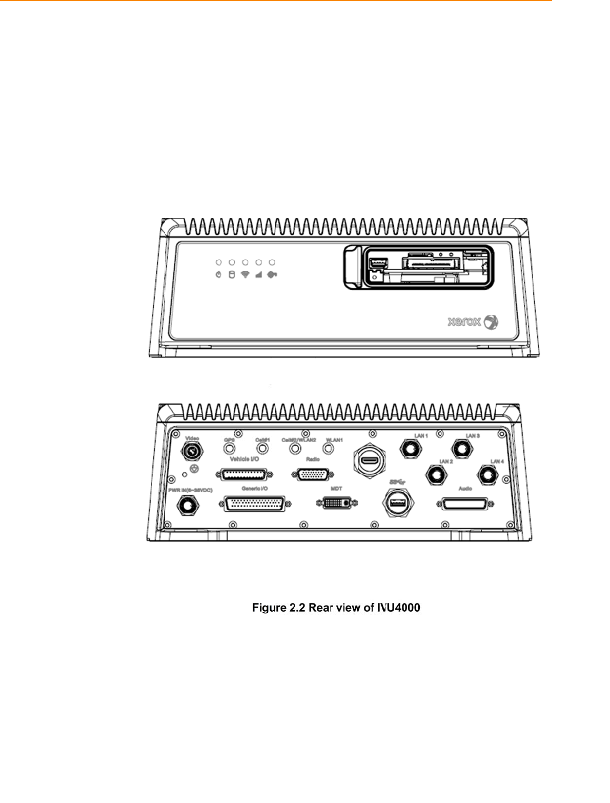
Figure 2.2 Rear view of
IVU4000
..............................................
8
2.1.1 Installing CFast & SIM card…
...........................................................
9
Installation Procedures
2.3
2.2.1 Connecting the Power
Cord..........................................................
9
Table 2.1: Pin Definition of Power Cord
......................................
9
2.2.2 Power
Connector ..........................................................................
9
Figure 2.6 Power connector
outlook
............................................
9
Table 2.2: Pin
Definition
of
Power Connector (Molex
Manufacturer
Part
no.0430451200)
................................................
10
Figure 2.7 Power connector photo
............................................
10
Running the BIOS Setup
Program
..........................................................
10
Chapter
3 Switches setting and I/O Connectors………. ..13
3.1 Setting Switches…………………………………………
....................................
13
3.1.1 Switches List……………………………............................................
13
3.2
3.3
3..1.
2
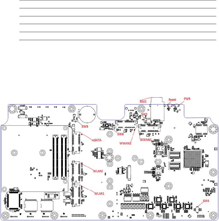
Switch Location………………..................................................................
1
3
3.1.3 Switch Setting……………………………………………………...........
13
3.1.3.1 MiniPCIe (WWAN) Power Voltage Setup (SW2)…………………13
3.1.3.2 MiniPCIe(WWAN) Support WWAN Module Setup (SW3)………13
3.1.3.3 CAN BUS Termination(Only for test use)(SW6)…………………14
3.1.3.4 MiniPCIe(WWAN) Power Voltage Setup (SW8)…………………14
3.1.3.5 MiniPCIe(WWAN) Support WWAN Module Setup(SW9)……….14
3.1.3.6 I/O DB9 PIN9 Select (ON TOP LAYOUT)(CN15)………………..14
LED Indicator………………………………………………………………….14
I/O Connectors Pin Assignment……………………………………..……..15
3.3.1 Power Connector………………………………………………………15
3.3.2 HDMI Connector………………………………………………………..15
3.3.3 Smart Display Connector……………………………………………..16
3.3.4 USB Connector (Rear side)…………………………………………..17
3.3.5 USB Connector (Front side)………………………………………….18
3.3.6 VGA & RS-232 Connector……………………………………………19
3.3.7 Video Input Connector………………………………………………..20
3.3.8 VI/O Connector……………………..…………………………………21
3.3.9 Generic I/O Connector………………………………………………..22
3.3.10 LAN Connector……………………………………………………….23

IVU4000 User Manual 1
Chapter 4 Software Demo Utility
Setup
...............
29
4.1 Introduction………………………………………………………………………30
4.2 IVCP Demonstration…………………………………………………………….30
4.2.1 Information…………………………………………………………………30
4.2.2 Mode Control………………………………………………………………31
4.2.3 Low voltage Protection……………………………………………………32
4.2.4 Event Delay………………………………………………………………...33
4.2.5 Alarm………………………………………………………………………..34
4.2.6 Watchdog…………………………………………………………………..35
4.2.7 G-Sensor…………………………………………………………………..36
4.2.8 Peripheral………………………………………………………………….37
4.2.9 Storage……………………………………………………………………..38
4.2.10 Digital IO………………………………………………………………….39
4.2.11 P-sensor………………………………………………………………….40
4.3 VCIL Demonstration…………………………………………………………….41
4.3.1 Port selection………………………………………………………….….41
4.3.2 Information…………………………………………………………….….42
4.3.3 Option…………………………………………………………………..….43
4.3.4 CAN/J1939/OBD2/J1708/J1587………………………………………..44
4.4 Smart Display Demonstration……………………………………………….…45
4.4.1 Information…………………………………………………………….….46
4.4.2 Backlight………………………………………………………………..….47
4.4.3 Hot Key………………………………………………………………….…48
4.4.4 Peripheral……………………………………………………………….…49
4.5 GPS Demonstration………………………………………………………….….50
4.5.1 Port selection……………………………………………………………...50
4.5.2 Information…………………………………………………………………51
4.5.3 NEMA………………………………………………………………………52
Appendix A MDT…………………………………53
A.1 MDT-1000 Specification………………………………………………….……..54
Table A.1 MDT Specification…………………………………….54

Chapter 1
1 General Information
This chapter gives background
information on the IVU4000 Premium
Computing Box.
Sections include:
Introduction
General Specifications
Dimensions
1.
IVU40
0
1
Intr
o
I
c
f
l
M
s
I
(
B
J
c
d
a
d
a
0
0UserMan
u
o
ductio
n
I
VU4000 is
c
omputing
b
f
or eBus a
n
l
ike the wid
e
M
IL-STD-8
1
s
ystem. Gu
I
VU4000 c
o
(
Tire Press
u
B
us device
s
J
1939,OB
D
c
ommunic
a
d
river/vehi
c
a
lso reserv
e
d
eliver diff
e
a
nother to
p
IVU40
0
u
al
n
an industri
a
b
ox design
e
n
d BRT( Bu
s
e
working t
e
1
0G and 5
M
arding aga
i
o
mbined wi
t
u
re Monito
r
s
. It has du
a
D
-II) for vehi
a
tion (WWA
c
le/location
/
e
d two dis
p
e
rent applic
a
p
assenger
t
0
0 I/O Ove
r
a
l-grade, p
o
e
d to provi
d
s
Rapid Tr
a
e
mperatur
e
M
3 standar
d
i
nst damag
e
t
h variety o
f
r
ing Syste
m
a
l CAN BU
S
cle diagno
s
N, WLAN)
e
cargo infor
m
p
lays/dual
a
a
tions to di
f
t
o IVI and d
r
view
o
wered by I
d
e high qua
a
nsit). It ca
n
e
range (-3
0
d
. Its speci
a
e
from tran
s
f
I/O conne
c
m
), Rear vie
w
S
ports an
d
s
tics and dr
e
nable IVU
4
m
ation bac
k
a
udio interf
a
f
ferent disp
l
d
igital signa
g
ntel® Atom
™
lity video s
u
n
work in e
x
0
℃-65℃) a
n
a
l power pr
o
s
ient car p
o
c
tors can b
e
w
Camera
(
d
support s
e
iver behavi
o
4
000 to se
n
k
to the co
n
a
ces suppo
l
ays; eg:on
e
g
e applicat
i
™
E3827 S
O
u
rveillance
a
x
treme envi
r
n
d anti-sho
c
o
tection sur
o
wer.
e
connecte
d
(
for parkin
g
e
veral kind
o
o
r manage
m
n
d importa
n
n
trol center.
r
ting differe
e
applicatio
n
on.
O
C dual cor
e
a
nd fleet m
r
onments
w
c
k/vibratio
n
r
ges from i
m
d
to device
s
g
monitorin
g
o
f vehicle
p
m
ent. Build
-
n
t
Furthermo
e
nt resoluti
o
n to a fleet
e
CPU
anagemen
t
w
ith feature
s
n
to pass
m
pacting th
e
s
like TPM
S
g
) and CAN
p
rotocols (e
.
-
in wireless
re, IVU400
0
o
ns can
driver and
t
s
e
S
.
g.
0
3TREK-57
0
0
/303 User
M
M
anual
IVU4000 User Manual 4
Chapter 1 General Information
1.2General Specifications
Features
Intel® Atom™ E3827 SOCDualcorehighperformanceprocessorformultitasking.
Embeddedvideoencodersupportsupto4analogvideoinputsforD1,30fpsresolutionand4audioinputs
Cfasttraywithkey‐lockprotection.
EasilypairedwithMDTin‐vehiclesmartdisplaysviaasingle‐cableconnection.
Intelligentvehiclepowermanagementsystemforignitionon/off/delayandpowerprotectionfunctions.
VehiclediagnosticinterfacewithconfigurabledualCAN(J1939,OBD‐II/ISO15765)andJ1708protocols.
Built‐inLTE/GNSS/WLAN(withdualSIMcards)modules.
AdvancedShock&anti‐vibrationcertifiedbyMIL‐STD‐810G,EN60721‐3(5M3)
Richmanagement&videoSDK,testutilityforcustomerevaluating.
Specifications
Core
ProcessorIntelBayTrailSOC,AtomE3827
Memory1xSO‐DIMMsocket
4GBDDR3L‐1600Non‐ECCmemorymodule;
GraphicIntelHDgraphics44001.1GHz
VideoHWEncoderStretchS7,supportH.264,MJPEGformat;ResolutionuptoD1,30fps
perchannel
O.SWE8S32bits asdefault.
Storage
CFast1xexternalaccessibleCFastslotwithcover,
Defaultconfiguration:4GB,SLCSQFlashCFastcard
mSATA1xmSATAslot,supportsystembootup
Defaultconfiguration:16GB;
Display
DVI‐I(*1)
15V/1.2ApoweroutputforMDTsmartdisplayunit
1x18‐bitsLVDS(1024x768MDT)
1xLine‐Out(*2)(ForSpeakersonMDT)
2xUART(TX/RX,TX/RX/RTS)(ForT/S,Hotkeys,brightness,light
sensorcontrol)
1xUSB2.0TypeA
1xResetButtonSignal
1xMIC‐in
HDMI1xHDMI1.3b(Resolutionupto1920x1080)
I/O
VehicleI/OPort2xCANBus(SupportRawCAN,J1939,OBD‐II/ISO15765;FW
configurable)
2xJ1708(SupportJ1587)
1x4‐wireRS‐232/422/485(DefaultRS‐485,bysoftwaresetting)
GenericI/OPort2x4‐wireRS‐232
4xIsolatedDI(DryContact)
4xIsolatedDO(Opencollectoroutput,drivingbyrelay)
1xLine‐Out(*2)
1xMic‐In
AudioI/O4Xcodec
RadioI/OTBC
StandardI/OPort1xUSB2.0TypeA(Frontside)
1xUSB3.0TypeA(Rearside,withcableclip)

5 IVU4000 User Manual
1xHighSpeedFullRS‐232,DB‐9(Pin9=Ring,12V/5V@0.5AisBOM
optionalbyjumpersetting)
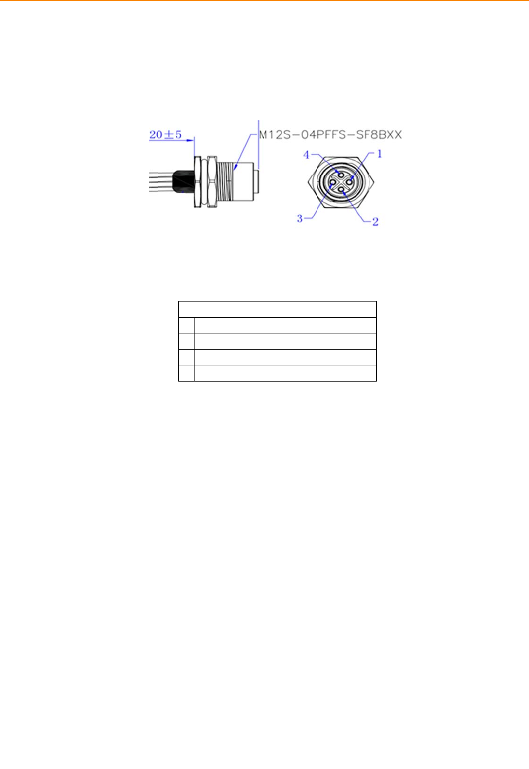
4xGigaLAN,with4‐pinM12connector
Video/Audioinput
(AV1&AV2,viadual
DVI‐Iconnector)
4‐chVideoinputs,VideoCompression:supportH.264,MJPEGformat;
ResolutionuptoD1,30fpsperchannel
4‐chmonoAudioinputs,AudioCompression:G.711
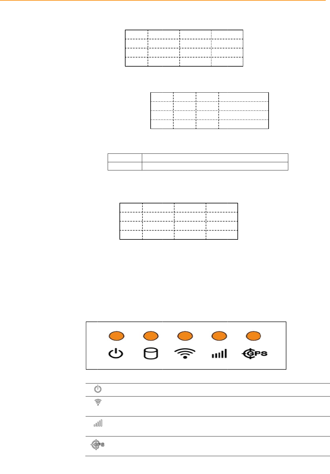
LED5 xLEDs (PWR(Red),Storage(Green),
WLAN(Green),WWAN(Green),GPS(Yellow)
PowerButtonViaMDT(In‐VehicleSmartDisplay);SystemispoweredonbyIgnition
indefault
ResetButtonViaMDT1xResetbutton(Rear side)
RF
WLAN IEEE802.11a/b/g/nviaFullMini‐PCIeSlot
WWAN4G(LTE,HSPA+,GSM/GPRS/EDGE,EV‐DOReva1,1xRTT):Sierra
WirelessMC73xxviaFullMini‐PCIeSlot
(Default:MC7354forUS)
GNSSBuild‐inu‐bloxMAX‐M8L GPS/Glonass/Beidoumodule,supportAGPS
Antenna4xSMAtypeantennaholeforGPS,WiFI,WWAN/Cell#1,)
WiFi#2/Cell#2
Power
VoltageinputSupports12/24Vcarpowersystem.(9V~32VwideDCinput 10A,ISO
7637‐2&SAEJ1113compliant.)
IntelligentVehicle
Power
Management(iVPM2.0)
Systempoweron/off/hibernatemanagement(e.g.Programmable
IgnitionOn/OffTimedelay)
SupportWakeupEvents:
‐Alarm(RTC)Wakeup.
‐WakeupbyCall/SMS.
‐WakeupbyG‐sensor.
Systempowerprotection(e.g.CarBatteryLowVoltageProtection)
Systemmonitoringanddiagnostic
MechanicalDimensions(WxHxD)4.92"x13.86"x11.44"(125mmx352mmx290.5mm);
Weight17lb(7.72Kg)
Environment
IPRatingIP54
Vibration/ShockMIL‐STD‐810G,EN60721‐3(5M3)
EMCFCC
SafetyUL/cUL,CB
VehicleRegulationSAEJ1455classC,ISO7637‐2,
RFRegulationFCCID
OperatingTemperature‐30°C~65
°
C
StorageTemperature‐40°C~80°C
*1:TobepairedwithMDTdirectly.(Single‐cableconnection)
*2:Supportdualindependentaudiostreams.(i.e.TheLine‐Outinterfacein"SmartDisplayPort"and
"GenericI/OPort"aredrivenbydifferentAudiocodecs.)
IVU4
1.
3
000 User M
a
3
Dim
e
a
nual
e
nsion
s
Figure 1
s
(inch
e
.1 IVU4000
e
s)
0
dimension
6
s
Chapter 1 General Information

Chapter 2
2 System Setup
This chapter details system setup
on IVU4000
Sections include:
A Quick Tour of the Computer
Box
Installation Procedures
Running the BIOS Setup
Program
2.
IVU-
4
1
A Q
u
4
000 User
M
u
ick To
u
Before
familia
r
which
a
M
anual
u
r of th
starting to
r
with the l
o
a
re illustrat
e
e IVU
4
set up the
o
cations an
d
e
d in the fi
g
Fig
u
Figu
4
000 C
o
In-Vehicle
d
functions
g
ures belo
w
u
re 2.1 Fro
re 2.2 Rea
r
8
o
mputi
n
Computin
g
of the cont
w
.
nt view of
r
view of I
V
n
g Box
g
Box, take
r
ols, drives
,
I
VU4000
V
U4000
a momen
t
, connecto
r
t
to becom
e
r
s and port
s
e
s
,
M
2
2.1.
sl
o
M
emoryandW
W
2
.2
In
s
2.2.
C
o
p
u
m
r
e
T
P
1
2
3
4
1 Install
RemoveC
F
o
tbecausedef
a
W
ANWIFIinst
a
s
tallati
o
1 Conn
e
onnect the
u
ting Box.
m
arked, "+";
e
served for
t
Note! I
g
s
a
T
able 2.1:
P
in
ing CFa
s
F
astdoorscre
w
a
ultpriorityisS
Figure
2
a
llation
o
n Pro
c
e
cting th
e
three pin
w
On the op
e
one pin i
s
t
he ignition
g
nition on/
o
s
o that you
c
a
ge and co
n
P
in Defini
t
s
t Card &
w
andcaninstal
l
IM1.Ifyouins
e
2
.3 Installi
n
edure
s
e
Power
C
w
ate
r
proof
p
e
n-wire en
d
s
reserved
signal with
o
ff setting:
T
c
an power
o
n
nect the I
V
t
ion of Po
w
Defini
t
GND
CarPo
w
GND
IGNITI
9
SIM car
d
lCFastCard&
S
e
rttoSIM2slo
t
n
g CFast c
a
s
C
ord
p
owe
r
cord
d
, one pin
for groun
d
an “ignitio
n
T
he IVU400
0
o
n/off the I
V
V
U4000 veh
wer Cord
t
ion
wer+
I
ON
d
S
IMCarddirec
t
t
,youhaveto
m
a
rd & SIM
c
to the DC
is reserve
d
d
and is
m
n
” mark.
0
supports
a
V
U4000 via
icle ignition
C
T
T
T
T
SIM1 SI
M
TREK-68
8
t
ly.Pleaseinse
r
m
odifysetting
o
c
ard
inlet of the
d
for positi
v
m
arked, "-";
a
n ignition o
the ignition
switch.
C
olo
r
T
BC
T
BC
T
BC
T
BC
2 CFastCard
8
User Manu
a
r
tSIMCardfro
m
o
fSDK.
e
In-Vehicle
v
e voltage
a
and, one
o
n/off functi
o
n
signal/volt
-
a
l
m
SIM1
Com-
a
nd is
pin is
o
n
-
Chapter 2 System Setup
IVU-
4
2.2.
4
000 User
M
2 Powe
M
anual
r Conne
c
F
Powe
r
1D
C
2D
C
3D
C
4IG
N
c
tor
F
igure 2.4
P
r
inputconn
e
C
‐IN_‐
C
‐IN_+
C
‐IN_‐
N
ITION_SE
N
P
owe
r
con
n
e
ctor
N
SE
1
n
ector out
l
ook
2.3Running the BIOS Setup Program
In most cases, the computer will have been properly set up and configured by the
dealer or SI prior to delivery. However, it may still be necessary to adjust some of the
computer's BIOS (Basic Input-Output System) setup programs to change the system
configuration data, like the current date and time, or the specific type of hard drive
currently installed.
The setup program is stored in read-only memory (ROM). It can be accessed either
when turning on or resetting the computer, by pressing the “Del” key on the keyboard
immediately after powering up the computer.
The settings that are specified with the setup program are recorded in a special area of
the memory called CMOS RAM. This memory is backed up by a battery so that it will
not be erased when turning off or resetting the system. Whenever the power is turned
on, the system reads the settings stored in CMOS RAM and compares them to the
equipment check conducted during the power on self-test (POST). If an error occurs,
an error message is displayed on screen, and the user is prompted to run the setup
program.

IVU-4000 User Manual 1
Chapter 3
4 Switches Setting and
Connectors
This chapter explains how to set
up the In-Vehicle Computing Box
hardware, including instructions
on setting and how to set
switches and read indicators.
Sections include:
Setting Switches
Indicators introduction
I/O connectors pin assignment
3
3
.1
S
e
3.1
.
3.1
.
3.1
.
e
tting
S
.1 Switc
h
.2 Switc
h
.2 Switc
h
S
witche
s
It is po
the ne
e
h
es List
Switch
e
SW2
SW3
SW4
SW6
h
es Loc
a
h
es Setti
n
3.1.3.1
M
s
ssible to c
o
ds of the a
p
e
s
a
tion
n
g
M
iniPCIe(W
W
o
nfigure th
e
p
plication b
Description
MiniPCIe(
W
ClearCMO
S
CANBUST
e
MiniPCIe(
W
W
AN1)Pow
e
e
In-Vehicl
e
y resetting
t
W
WAN1)Po
w
S
e
rmerater(
O
W
WAN2)Po
w
e
rVoltageS
e
e
Computi
n
t
he switche
s
w
erVoltage
S
O
nlyfortest
u
w
erVoltage
S
e
tup(SW2)
n
g Box to
m
s.
S
etup
u
se)
S
etup
m
atch
3
IVU-
4
3
.2
L
E
4
000 User
M
3
3
E
D Indi
c
M
anual
3.1.3.2
C
3
.1.3.3CA
ON/O
N
OFF/O
F
3
.1.3.4Mi
c
ator
Power
A
indicat
o
WLAN
Indicat
o
WWA
N
Indicat
o
GPS A
c
Indicat
o
3
.
3
.
3
.
C
learCMOS
NBUSTerm
N
Disabl
e
F
FEnabl
e
niPCIe(WW
A
A
ctivity
o
r LED
Activity
o
r LED
N
Activity
o
r LED
c
tivity
o
r LED
3.8
V
O
S
W
O3.3
V
O
3.5
V
S
W
O
F
O
N
O
F
ON
.
8V
OF
F
SW6
.
3V
.
5V OF
F
m
ination(On
l
e(Default)
e
CANBUST
A
N2)Power
When the
s
up.(Red co
The WLAN
show the a
c
This LED i
s
The WWA
N
the activity
This LED i
s
The GPS
a
GPS activi
t
chips.(Yell
o
N
SW
O
F
W
2.1
FF O
N
FF O
F
ON
W
3.1
OFF
OFF
F
F
N
SW3.2
F
F
F
.1
OF
F
SW6
ON
OF
F
F
1
l
yfortestu
s
erminator(
1
VoltageSet
u
s
ystem is in N
O
lor)
activity indic
a
c
tivity of the
W
s
controlled di
r
N
activity indi
c
of the WWA
N
s
controlled di
r
a
ctivity indicat
o
t
y. This LED i
s
ow
color)
O
F
O
F
SW
O
N
2.2
F
F
N
F
F
C
OFF
D
N
C
OFF
ON
SW3.3
SW6
.
OF
F
OF
F
ON
F
.2
F
s
e)(SW4)
1
20ohm)
u
p(SW6)
O
RMAL mod
e
a
tor is an oran
W
LAN module
r
ectly by the
W
c
ator is a gree
n
N
module.(Gre
r
ectly by the
W
o
r is an orang
e
s
controlled di
r
F
F
F
F
2.3
N
lear CMOS
escription
ormal
lear CMOS
.
3
F
F
e
, this LED wi
l
n
ge LED, and
.(Green color
)
W
LAN modul
e
n LED, and fl
a
e
en color)
W
WAN modul
e
e
LED, and is
rectly by the
G
l be light
f
lashes to
)
e
.
a
shes to sho
w
e
.
used to sho
w
G
PS
w
w
3
3
.3
I/
O
3.3
.
3
.
Syst
e
O
Conn
.1
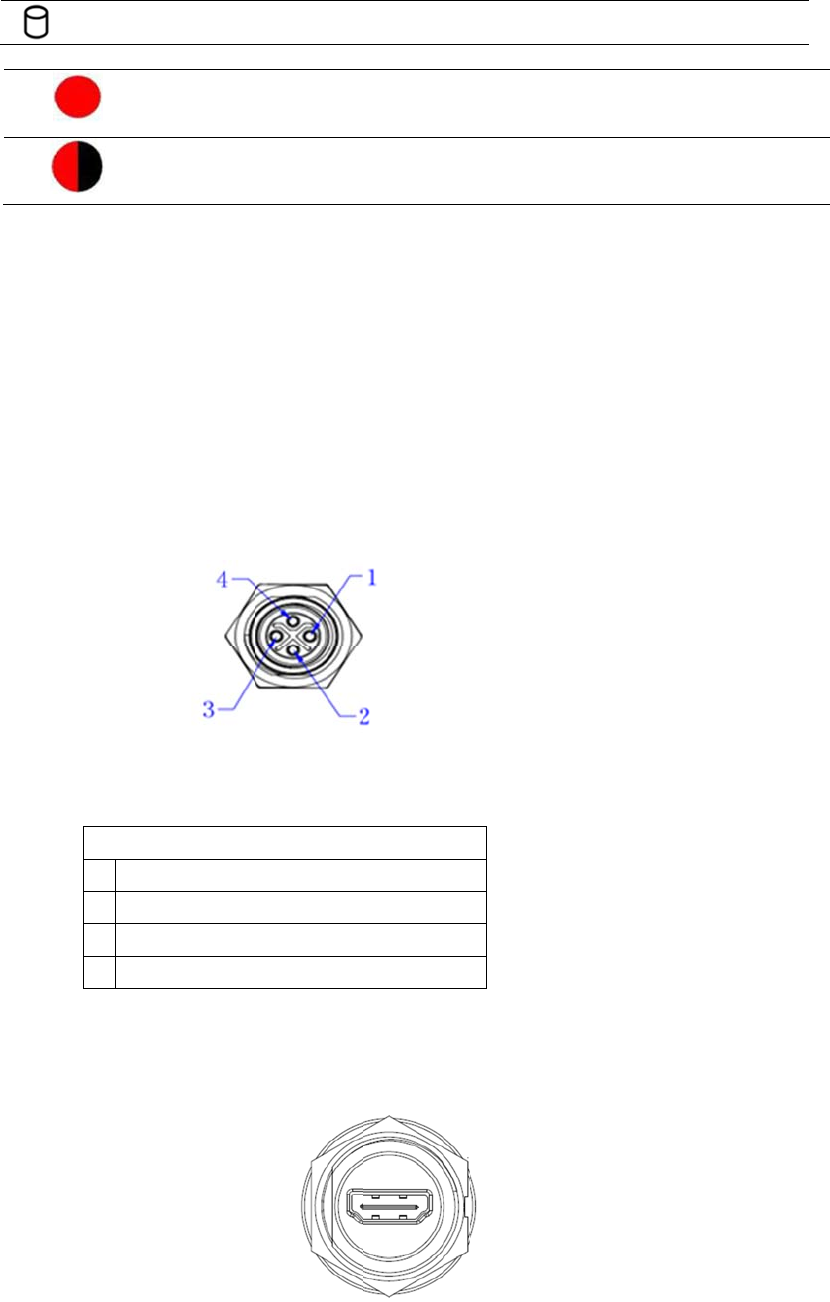
Pow
.
3.2
HD
Storag
e
Indicat
o
e
m power in
ectors
er con
n
F
Powe
r
1D
C
2D
C
3D
C
4IG
MI Co
n
Connecto
e
Access
o
r LED
dicator LED
Red LED k
e
Normal mo
d
System is in
Red LED fl
a
Boot loader
F/W can be
Pin As
s
n
ector
F
igure 2.4
P
r
inputconn
e
C
‐IN_‐
C
‐IN_+
C
‐IN_‐
N
ITION_SE
N
n
necto
r
r type: HD
M
The Storag
show the a
c
e
ep light
d
e
n
NORMAL m
o
a
shing
mode
update
signm
e
P
owe
r
con
e
ctor
N
SE
r
MI Conn. 1
e Access ind
c
tivity of the
S
o
de
e
nt
nector out
9P 0.5mm
icator is a gre
S
torage tran
s
look
180D(F)
e
en LED, and
f
s
portation. (G
r
f
lashes to
r
een color)
IVU-
4
Pin
1
2
3
4
5
6
7
8
9
10
4
000 User
M
Signal De
p
T
TM
D
T
T
TM
D
T
T
TM
D
T
3.3.3
M
D
Pin
1
3
5
7
9
11
13
15
17
19
21
23
M
anual
Tabl
e
p
iction
T
MDS
_
DAT
A
D
S_DATA2+
T
MDS
_
DAT
A
T
MDS
_
DAT
A
D
S_DATA1
S
T
MDS
_
DAT
A
T
MDS
_
DAT
A
D
S_DATA0
s
T
MDS
_
DAT
A
TMDS Clo
c
D
T Co
n
Sign
a
LVD
S
LVD
S
LVD
S
Vdd_
e
LVD
S
LVD
S
LVD
S
BTN_
R
USB_
P
USB_
R
A
UD
_
SPK
HDMI Con
A
2+
Shield
A
2-
A
1+
S
hield
A
1-
A
0+
s
hield
A
0-
c
k
n
necto
r
a
l
S
1_p/[D0]
S
1_RTN
S
1_n
en
S
3_p/[D3]
S
3_RTN
S
4_n
R
S
T
P
R
TN
_
RTN
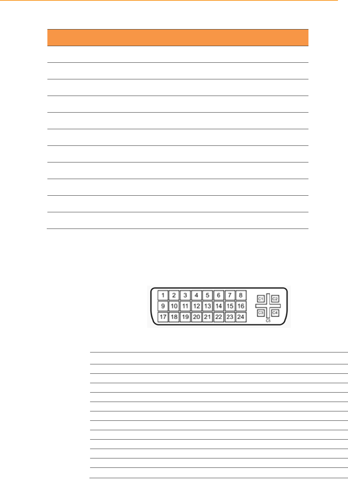
nector Pin
A
Pin Si
11
12
13
14
15
16
17
18
19
r
(DVI-I
1
A
ssignmen
t
g
nal Depict
i
TM
D
T
HD
M
H
)
Pin
2
4
6
8
10
12
14
16
18
20
22
24
t
i
on
S_Clock Sh
i
MDS Clock-
CEC
Reserved
SCL
SDAA
GND
M
I_Power(5
V
H
DMI_HPD
Signal
LVDS1_
n
LVDS2_
p
MDT_DE
T
VBL_en
LVDS3_
n
LVDS4_
p
LVDS4_
R
RTN
USB_N
RTN
Cover_M
A
UD_RT
N
ield
V
)
n
p
/[D1]
T
#
n
p
/[CLK]
R
TN
IC
N
C1
C2
C3
C4
C5
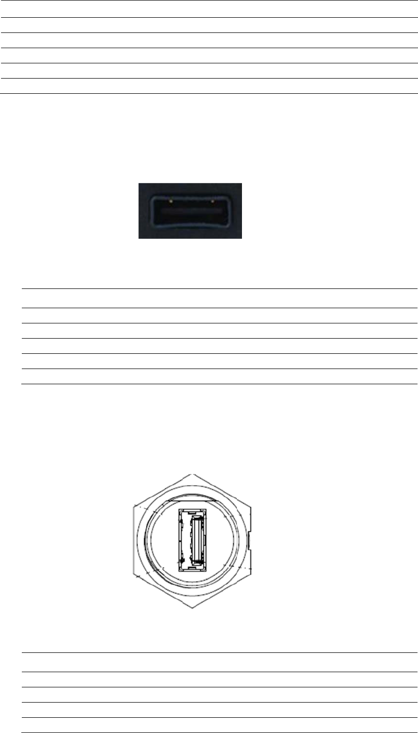
3.3.4
U
S
3.3.5
U
S
C
o
DC-I
N
DC-I
N
DC-I
N
PWR
_
PWR
_
S
B Co
n
Table 3. :
Pin
1
2
3
4
S
B Co
n
o
nnector ty
Table 3. :
Pin
1
2
3
N
N
N
_
RTN
_
RTN
n
nector
Connect
o
USB Conn
e
Signal D
Vcc
USB_Da
t
USB_Da
t
GND
n
nector
pe: Single
U
USB Conn
e
Sig
n
Vcc
US
B
US
B
(Front
o
r type: Sin
g
e
cto
r
epiction
t
a-
t
a+
(Rear
U
SB
A
-Typ
e
e
cto
r
n
al Depictio
B
_Data-
B
_Data+
side)
g
le USB A-
T
side)
e
with wat
e
n
T
ype
r
-proof housing
IVU-
4
4
000 User
M
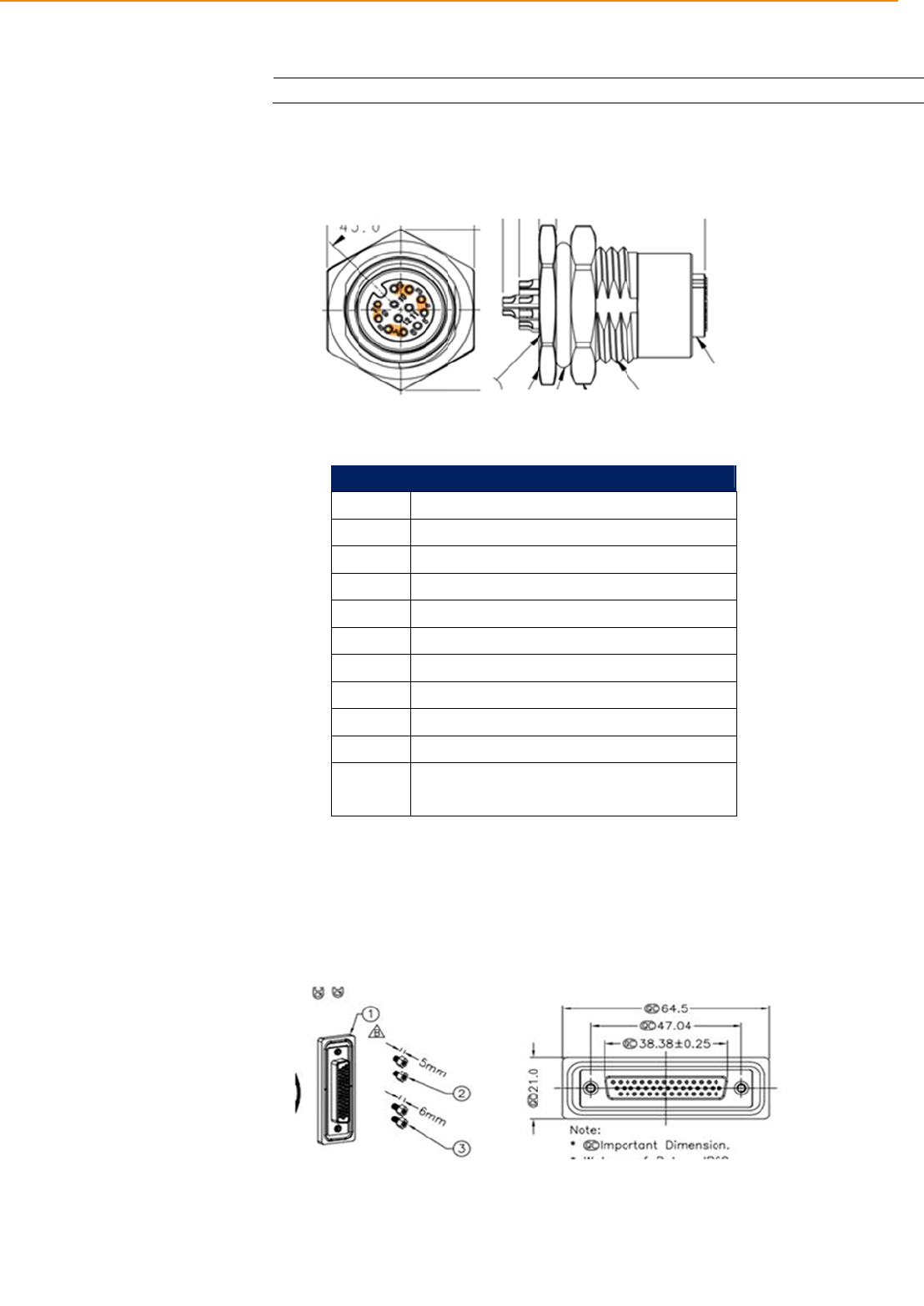
3.3.6
V
i
d
3.3.7
V
e
M
anual
4
d
eo Inpu
t
Connect
o
Femaler
i
Ta
b
e
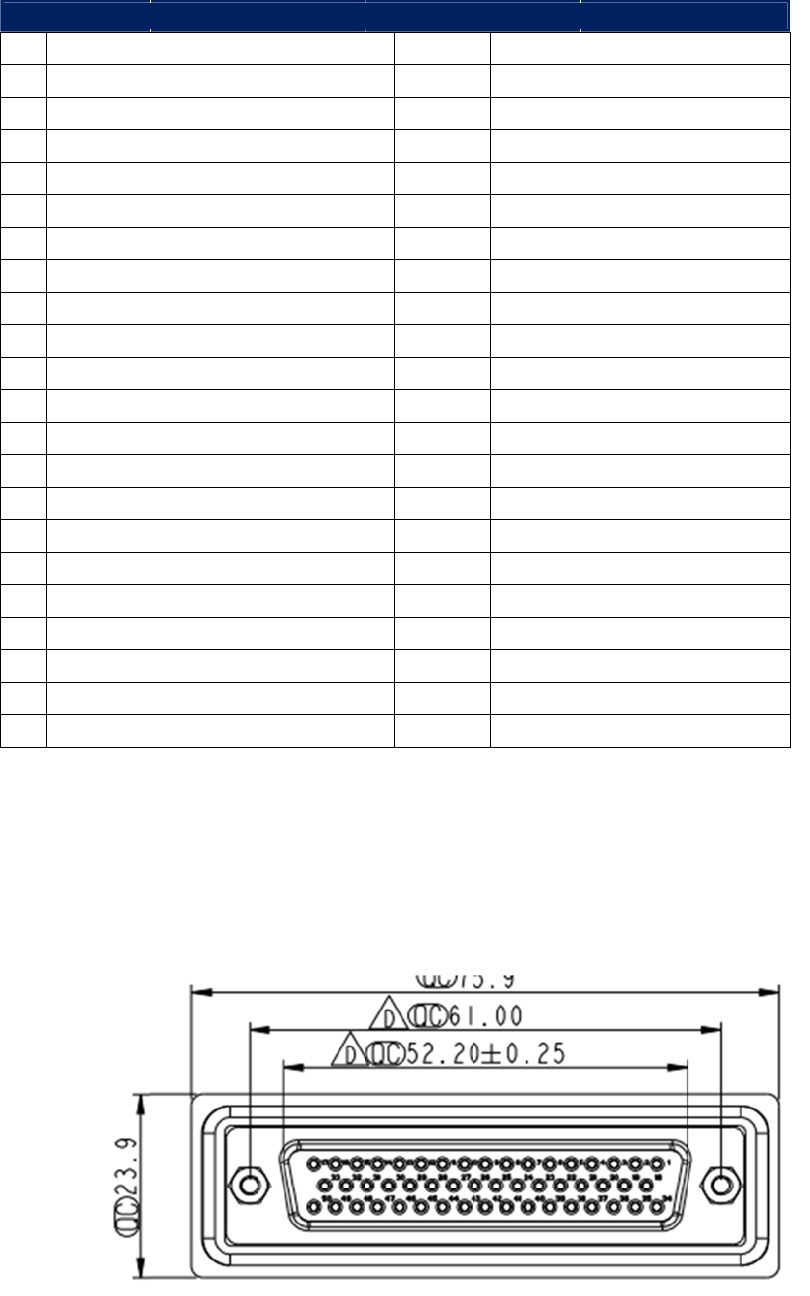
hicle I
/
VI/O
cont
a
Connec
GN
D
t
Conne
c
o
rtype:M12
ghtangle
b
le VIO
C
1 Vid
e
2 Vid
e
3 Vid
e
4 Vid
e
5 Vid
e
6 Shi
e
7 Vid
e
8 Vid
e
9 Vid
e
10 Shi
e
11 NC
12 NC
/
O Con
PortisTREK’
s
a
insDualCA
N
tor type: 4
D
c
tor
12PIN
C
onnect
o
e
o_RTN1
e
o_RTN4
e
o_IN4
e
o_RTN3
e
o_IN3
e
lding(ifn
e
e
o_IN2
e
o_RTN2
e
o_IN1
e
lding(ifn
e
nector
s
nextgenera
t
N
BusandDua
4
4PIN D-S
U
1
o
r Pin As
s
e
eded)
e
eded)
t
ioncommun
lJ1708interf
a
B FEMALE
s
ignment
i
cationinterf
a
a
ce.
CONNECT
O
t
a
ceconnecto
r
OR
r
which
1
2
3
4
5
6
7
8
9
10
11
12
13
14
15
16
17
18
19
20
21
22
D
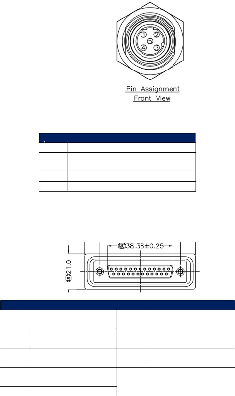
3.3.8
G
e
Table
V
COM1_R
X
COM1_C
T
COM1_T
X
COM1_R
T
COM1_R
T
COM2_R
X
COM2_C
T
COM2_T
X
COM2_R
T
COM2_R
T
COM3_R
X
COM3_C
T
COM3_T
X
COM3_R
T
COM3_R
T
CAN_P
CAN_N
CAN_RT
N
J1708_P1
_
J1708_P1
_
J1708_R
T
allasVehi
c
e
neric I
GenericI
interfac
e
HDCcon
n
V
IO Conn
e
X
T
S
X
T
S
T
N
X
T
S
X
T
S
T
N
X
T
S
X
T
S
T
N
N
_
P
_
N
T
N
leID
/O Co
n
/OPortisa
h
forperipher
a
n
ector(a.k.a.
e
ctor Pin
23
24
25
26
27
28
29
30
31
32
33
34
35
36
37
38
39
40
41
42
43
44
n
necto
r
h
ighdensityc
o
a
lcontrolbut
ExtendedI/
O
Assign
m
V
J
r
o
nnectorwhi
c
itismoreco
m
O
Port)onIVU
4
m
ent
V
ehicle_RT
COM4_R
X
COM4_CT
S
COM4_T
X
COM4_RT
S
COM4_RT
N
RTN
RTN
COM5_R
X
COM5_CT
S
COM5_T
X
COM5_RT
S
COM5_RT
N
ODBII_P
ODBII_N
ODBII_RT
N
J
1708_P2_
P
J
1708_P2_
N
J1708_RT
N
RTN
RTN
RTN
c
hprovidess
e
m
pactandco
s
4
000.
N
X
S
X
S
N
X
S
X
S
N
N
P
N
N
e
veralcomm
o
s
teffectivet
h
o
nI/O
anthe

IVU-4000 User Manual 2
Connector type: FEMALE D-SUB Conn. 50P
Table GIO Connector Pin Assignment
1 SIO_IN_C0 26 ISO_OUT0_COL
2 SIO_RTN_C0 27 ISO_OUT_RTN
3 SIO_IN_C1 28 ISO_OUT1_COL
4 SIO_RTN_C1 29 ISO_OUT_RTN
5 SIO_IN_C2 30 ISO_OUT2_COL
6 SIO_RTN_C2 31 ISO_OUT_RTN
7 SIO_IN_C3 32 ISO_OUT3_COL
8 SIO_RTN_C3 33 ISO_OUT_RTN
9 SIO_INC0:3_shield 34 EMER
10 SIO_IN_C4 35 EMER_RTN
11 SIO_INC_RTNC4 36 Odometer
12 SIO_IN_C5 37 Odometer_RTN
13 SIO_INC_RTNC5 38 RES_DRY_IN_0
14 SIO_IN_C6 39 RES_DRY_IN_1
15 SIO_INC_RTNC6 40 RES_DRY_IN_2
16 SIO_IN_C7 41 RES_DRY_IN_3
17 SIO_INC_RTNC7 42 RES_DRY_IN_RTN
18 SIO_IN_A0 43 RES_DRY_OUT_0
19 SIO_INA_RTN_A0 44 RES_DRY_OUT_RTN
20 SIO_IN_A1 45 RES_DRY_OUT_1
21 SIO_INA_RTN_A1 46 RES_DRY_OUT_RTN
22 SIO_IN_A2 47 RES_DRY_OUT_2
23 SIO_INA_RTN_A2 48 RES_DRY_OUT_RTN
24 SIO_IN_A3 49 RES_DRY_OUT_3
25 SIO_INA_RTN_A3 50 RES_DRY_OUT_RTN
Conne
c
3.3.9
L
A
c
tor type:
F
T
a
3.3.10
A
1 Han
d
2 Han
d
3 Goo
s
4 Goo
s
5 SPA
R
6 Spar
e
7 SPA
R
8 SPA
R
9 INT
E
A
N Con
F
EMALE M1
2
a
ble LA
N
1 T
X
2 R
X
3 T
X
4 R
X
5 Sh
i
A
udio c
o
Co
Table A
u
d
setSPK_p
d
set_SPK_n
s
eneckMIC
s
eneck_RT
N
R
EAudioI
n
e
_Audio_I
n
R
EAudioO
R
EAudio_
O
E
RIORLIN
E
nector
2
4P
N
Connec
t
X
+
X
+
X
‐
X
‐
i
elding
o
nnect
o
nnector ty
p
u
dio Con
n
N
n
n
_RTN
UT
O
UT_RTN
E
OUT
t
or Pin A
s
o
r
p
e: FEMAL
E
n
ector Pi
n
14
15
16
17
18
19
20
21
22
s
signme
n
E
D-SUB C
o
n
Assign
m
Handset
_
Handset
_
Interior
A
Interior
A
Exterior
A
Exterior
A
HOOK_O
F
GooseNe
MIC_PT
T
n
t
o
nn. 25P
m
ent
_
MIC
_
MIC_RTN
A
GCMIC
A
GCMIC_
R
A
GCMIC
A
GCMIC_
R
F
F
ck_PTT_N
R
TN
R
TN
IVU-
4
1
1
1
1
1
1
1
1
4
000 User
M
1
0
INTE
R
1
1 Shei
l
1
2 Inte
r
1
3 Inte
r
3.3.11
R
1 Voic
e
2 Voic
e
3 Voic
e
4 Voic
e
5 RAD
I
6 RAD
I
7 RTN
8 RAD
I
9 RAD
I
1
0 RAD
I
1
1 RAD
I
1
2 RAD
I
1
3 RAD
I
M
anual
R
IORLINEO
U
l
ding(PAs
i
r
iorSpeak
e
r
iorSpeak
e
R
adio c
o
C
o
Table R
a
e
RadioTX
e
RadioRT
e
RadioRX
e
RadioRT
I
O_EME
R
I
O_VOL_C
O
I
O_CTS
I
O_READY
I
O_CHAN_
S
I
O_CHAN_
R
I
O_CHAN_
S
I
O_CHAN_
R
U
TRTN
i
gnal)
e
r_p
e
r_n
o
nnect
o
o
nnector ty
a
dio Con
n
N
(analog)
N
(analog)
O
N/BUSY
S
EL_0
R
TN0
S
EL_1
R
TN1
23
24
25
o
r
y
pe: FEMA
L
n
ector Pi
n
14
15
16
17
18
19
20
21
22
23
24
25
26
P
2
PTT_RT
N
Exterior
Exterior
E D-SUB C
n
Assign
m
RADIO_
C
RADIO_
C
RADIO_
C
RADIO_
C
RTN
Radio_P
o
RADIO_
P
RTN
COM6_R
X
COM6_C
T
COM6_T
X
COM6_R
T
COM6_R
T
N
S
peaker_p
S
peaker_n
o
nn. 26
m
ent
HAN_SEL_
2
HAN_RTN
HAN_SEL_
3
HAN_RTN
o
wer_Cont
r
TT_N
X
T
S
X
T
S
T
N
2
2
3
3
r
ol
Chapter 5 Pin Assignments

IVU-4000 User Manual 28

Chapter 4
6 Software Demo Utility
Setup
This appendix explains the soft-
ware demo utility for IVU4000
Sections include:
Introduction
How to Set up Demo Utility

IVU-4000 User Manual 30
4.1Introduction
Xerox has developed demo utilities based on Xerox provided SDK APIs to let user
test the functions on IVU4000. This document describes the usage of each demo
utilities and also provide a basic concept of the application development on
IVU4000.
For technical support, contact Xerox application engineers worldwide. For news
updates, please visit our website : www.Xerox.com and MRM forum :
http://mrmforum.Xerox.com/index.aspx
4.2IVCPDemonstration
TheIVCPdemonstrationapplicationdemonstratetheusageofMRMIVCPAPIwhichisa
lightweightinterfacebetweenOS(Operatingsystem)andIVCP(IntelligentVehicleCo‐
Processor)allowusertoaccessthestatusofmachineandchangemachinebehaviorsuch
aspowermanagement,bootbehavior,peripheralcontroletc.
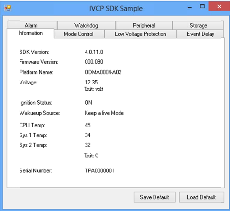
4.2.1 Information
Inthispage,thedemoapplicationshowsthecurrentstatusandbasicinformation.
IVU-
4
4
000 User
M
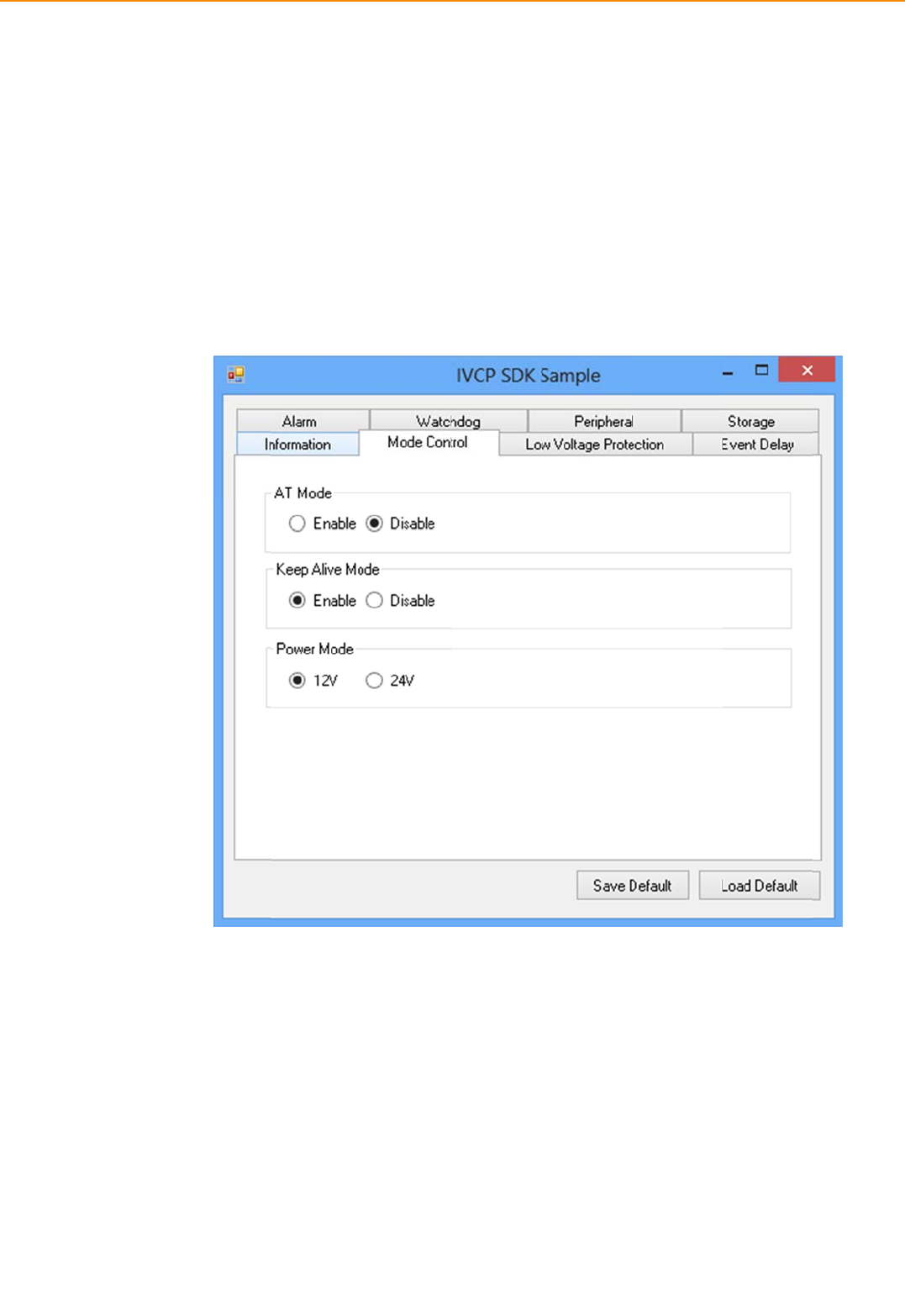
4.2.2
M
Inthispa
g
Press“Sa
Manage
m
Press“Lo
4.2.3
L
Youcan
e
thispage
Press“G
e
Press“Sa
Press“Lo
M
anual
M
ode Co
g
e,youcan
t
veDefault”
t
m
ent)contro
adDefault”
t
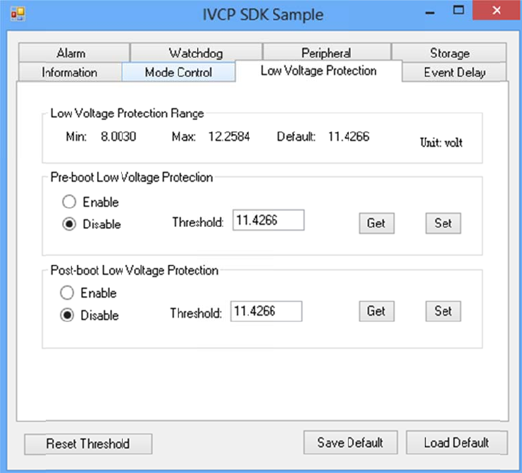
L
ow Volt
a
e
nable/disa
b
.
e
t”togetth
e
veDefault”
t
adDefault”
t
n
trol
t
oggle“AT
M
t
osetcurre
n
ller.
t
oloadthe
d
a
ge Pro
t
b
leandsett
h
e
currentthr
t
osetcurre
n
t
oloadthe
s
3
M
ode”and“
K
n
tsettingsa
s
d
efaultvalu
e
t
ection
h
epre‐boot
/
r
esholdvalu
e
n
tvalueasd
e
s
toreddefau
3
2
K
eepAlive
M
s
defaultval
u
e
s.
/
post‐bootl
o
e
andPress
“
e
faultvalue
ltvalues.
M
ode”.
u
eofVPM(V
o
wvoltagep
r
“
Set”tosett
ofVPMcon
t
V
ehiclePowe
rotectionth
r
t
hevalue.
t
roller.
r
r
esholdin
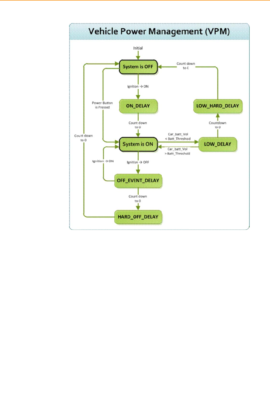
4.2.4
E
4.2.
4
IVU4
0
requi
E
vent De
4
.1 Power
c
0
00provide
s
rements.Th
lay
c
ontrol mec
s
VPM(Vehi
c
ebasicmec
h
c
hanism
c
lePowerM
h
anismissh
o
anagement)
o
wninthef
o
featuresto
o
llowingfig
u
fulfillspecif
i
u
re.
i
c
IVU-
4
The
p
Thei
g
state
Once
Whe
n
dela
y
isswi
OFF_
butt
o
data
a
After
IfHA
R
4
000 User
M
p
owerofsys
t
IgnitionON
g
nitionsign
a
andtheigni
itcountsto
IgnitionOF
F
n
thesyste
m
y
period(OFF
_
tchedback
t
EVENT_DEL
A
o
npress).Sy
s
a
ndprepari
n
theeventis
R
D_OFF_DE
L
M
anual
t
emcanbe
c
a
lcanbeuse
tionisturn
e
zero,thesy
s
F
m
ispowered
_
EVENT_DE
L
t
oON,theV
A
Ycountsto
s
temandap
n
gtoturnof
f
triggered,
V
L
AYcountst
o
c
ontrolledw
i
dtopower
o
e
dON,theV
P
s
temwillbe
onandthe
i
L
AY).During
P
Mcontroll
e
zero,theV
P
p
licationsw
h
f
thesystem
V
PMcontroll
o
zero,thes
y
3
iththefollo
w
o
norshutd
o
P
Mcontroll
e
poweredo
n
i
gnitionistu
thisperiod,
e
rwillstop
c
P
Mcontroll
e
h
ichreceiv
e
.
erstartsto
c
ystempow
e
3
4
w
ingevents:
o
wnthesyst
e
e
rwillcount
d
n
.
rnedoff,th
e
iftheigniti
o
c
ountdowna
e
rwilltrigge
r
e
sthisevent
c
ountdown
n
e
rwillbecut
e
m.Whent
h
d
ownadela
y
e
VPMcontr
o
o
n
ndresetth
e
r
anpowero
f
candopre‐
d
n
extdelayp
e
offabruptly
h
esystemis
y
period(O
N
o
llerwillco
u
e
OFF_EVEN
T
ffevent(i.e.
d
efinedtask
s
e
riod(HARD
y
toavoidun
inanOFF
N
_DELAY).
u
ntdowna
T
_DELAY.If
power
s
,likestorin
g
_
OFF_DELA
Y
expected
g
Y
).
systemhang.Aldo,onceVPMcontrollerentertheHARD_OFF_DELAYstage,theprocesscannotbe
reversed.
Lowpowerprotection
Toavoiddrainingpower,low‐powerprotectionistoensurethatthereisenoughpower
tostartthemachine.WhenthesystemisON,theVPMcontrollerwillmonitorthepowervoltage.If
thevoltageislowerthantheprogrammablethreshold(LOW_THRESHOLD),theVPMcontrollerwill
starttocountdownadelay(LOW_DELAY).DuringthestageofLOW_DELAYcountdown,ifvoltage
goesbackaboveLOW_THRESHOLD,theVPMcontrollerwillstopcountingdownandexit.
IfLOW_DELAYcountstozero,theVPMcontrollerwilltriggeranpoweroffevent(i.e.powerbutton
press)andstartstocountdownnextdelayperiod(LOW_HARD_DELAY).IfLOW_HARD_DELAYcounts
tozero,thesystempowerwillbecutoffabruptlytoavoiddrainingthepower.
4.2.4.2 Demonstration
Youcansetthedelayandharddelaytimeofthelowvoltageeventandignitionevent.
LowVoltageEvent
Delay:
ThedelaytimebeforeVPMtriggerapoweroffevent(i.e.powerbuttonpress).
HardDelay:
Thedelaytimecounteddownafterapoweroffeventistriggered.VPMwillforcepoweroffthe
machineiftheharddelaytimeiscounteddowntozero.
IgnitionEvent
OnDelay:
ThedelaytimebeforeVPMtriggeranpoweronevent(poweronthemachine).
OffDelay:
ThedelaytimebeforeVPMtriggeranpoweroffevent(i.e.powerbuttonpress).
HardOffDelay:
Thedelaytimecountedafteranpoweroffeventistriggered.VPMwillforcepoweroffthe
machineiftheharddelaytimeiscounteddowntozero.
Pre‐AlarmEvent
Delay:TBC
Press“SaveDefault”tosetcurrentvalueasdefaultvalue.
Press“LoadDefault”toloadthestoreddefaultvalues.
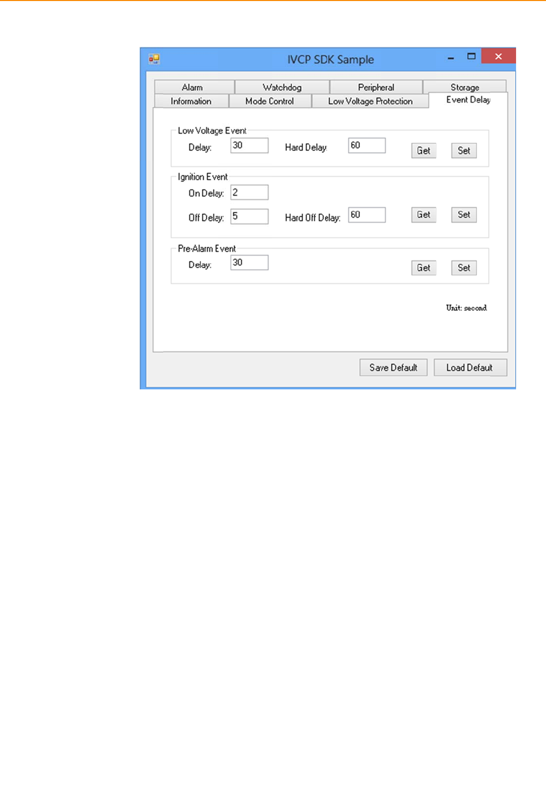
IVU-
4
Inthi
s
alar
m
Press
Press
4
000 User
M
4.2.5
A
s
page,you
c
m
asasyste
m
“SaveDefa
u
“LoadDefa
u
M
anual
A
larm
c
ansetthet
m
wakeupso
u
u
lt”tosetc
u
u
lt”toload
t
imeandset
u
rce.
u
rrentvalue
a
t
hestoredd
e
3
alarmwake
u
a
sdefaultv
a
e
faultvalue
s
3
6
u
ptimeto
V
a
lue.
s
.
PMcontroll
e
e
randenab
l
l
e/disablethe
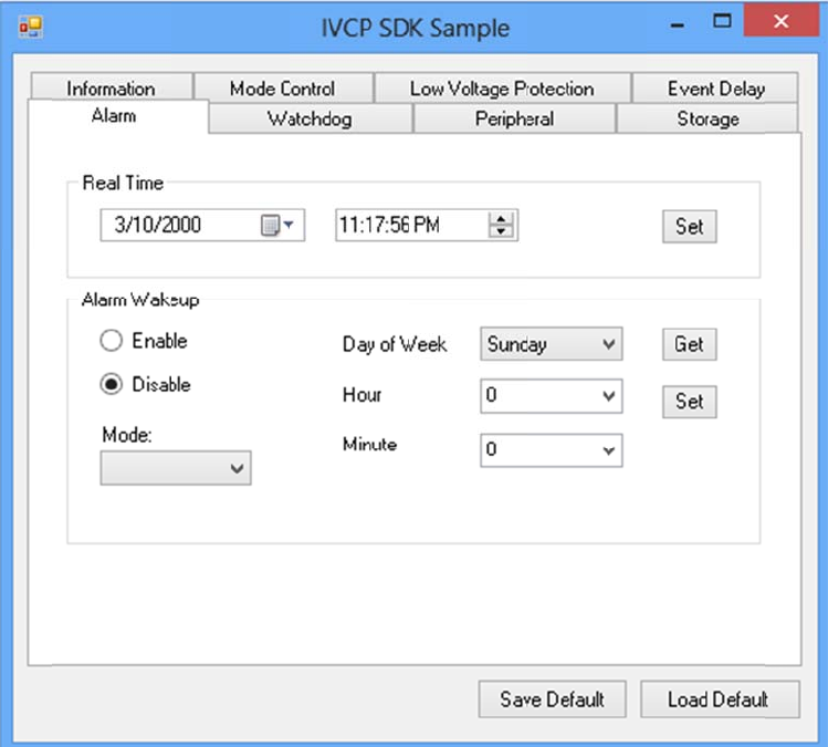
Inthi
s
watc
h
Whe
n
pow
e
tore
s
Press
Press
4.2.6
W
s
page,you
c
h
dogtoavoi
n
watchdog
i
e
roffthema
s
etthecoun
t
“SaveDefa
u
“LoadDefa
u
W
atchdo
g
c
anenable/
d
dunexpect
e
i
senabled,t
h
chineifitis
t
downtime
u
lt”tosetc
u
u
lt”toload
t
g
d
isablethe
w
e
dsystemha
h
eVPMcon
t
countedto
0
andkeepit
u
rrentvalue
a
t
hestoredd
e
w
atchdogfu
n
a
ng..
t
rollerwills
t
0
.Youcanp
r
counting.
a
sdefaultv
a
e
faultvalue
s
n
ctionands
e
t
artcountin
g
r
ess“Trigge
r
a
lue.
s
.
e
tthecount
g
downthet
i
”buttonwh
time(secon
imesetfor
w
ilewatchdo
g
d)forthe
w
atchdogan
g
iscountin
g
d
g
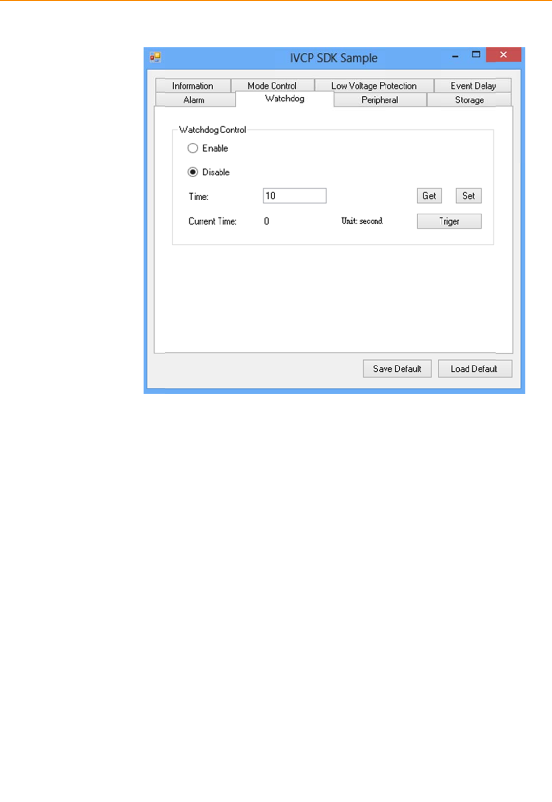
IVU-
4
Inthi
s
confi
g
4
000 User
M
4.2.7
P
s
page,you
c
g
ureeachs
e
M
anual
P
eripher
a
c
anenable/
d
e
rialportfun
a
l
d
isablethe
p
ctionssuch
a
3
p
eripheralfu
a
sRS‐232/R
S
3
8
nctionssuc
h
S
‐485/RS‐42
asWiFi/W
W
2
andenabl
e
W
AN/GPSa
n
e
/disableits
n
dalso
termination.
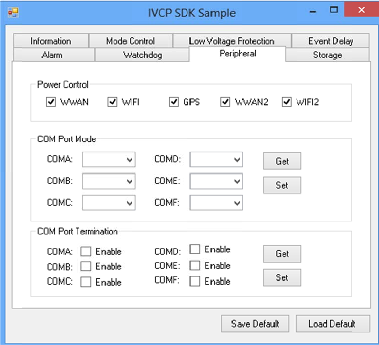
Inthi
s
4.2.8
S
s
page,you
c
S
torage
c
ansave/lo
a
darbitrary
d
d
atatothe
p
p
rivatestora
g
g
e(256byte
)onthema
c
c
hine.
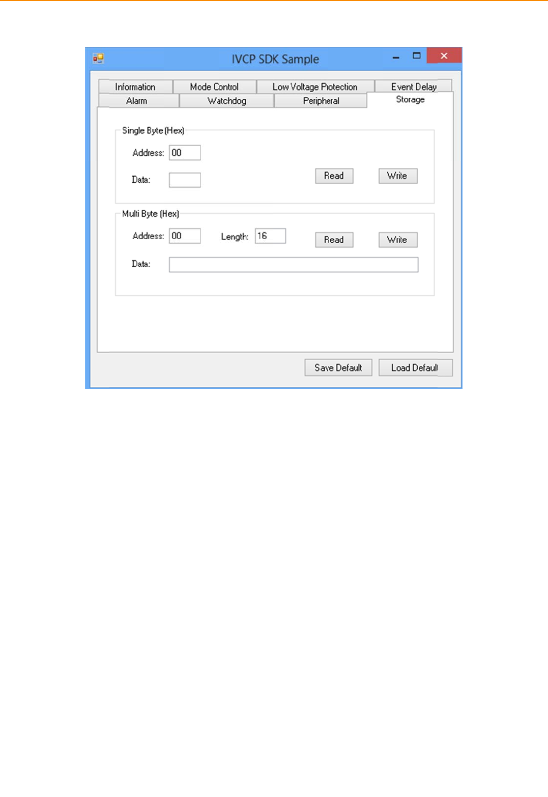
IVU-
4
4.
3
4.3.
Whe
n
Pleas
VCIL
p
4
000 User
M
3
VCI
The
V
Com
m
1 Port s
e
n
firstopen
V
eselectthe
p
ortpathin
M
anual
LDe
m
V
CILdemons
m
unicationI
e
lection
V
CILdemon
s
VCILportp
a
differentpl
a
m
ons
t
rationappl
i
n
terfaceLay
s
trationapp,
thandpres
s
a
tformshav
e
4
trati
o
i
cationdem
o
y
er)APIwhic
,
youwillse
e
s
Connectb
u
e
differentn
o
4
0
o
n
o
nstratethe
hallowuse
r
e
aportsele
c
u
tton.
o
des.Theco
usageofM
R
toaccessv
e
c
tionwindo
w
mmonpath
R
MVCIL(Ve
h
e
hicleproto
c
w
sasfollowi
atWindow
i
h
icle
c
oleasily.
ng.
i
sCOM7.
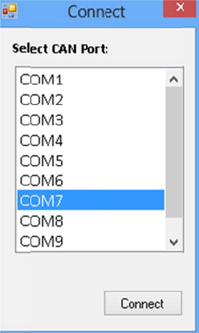
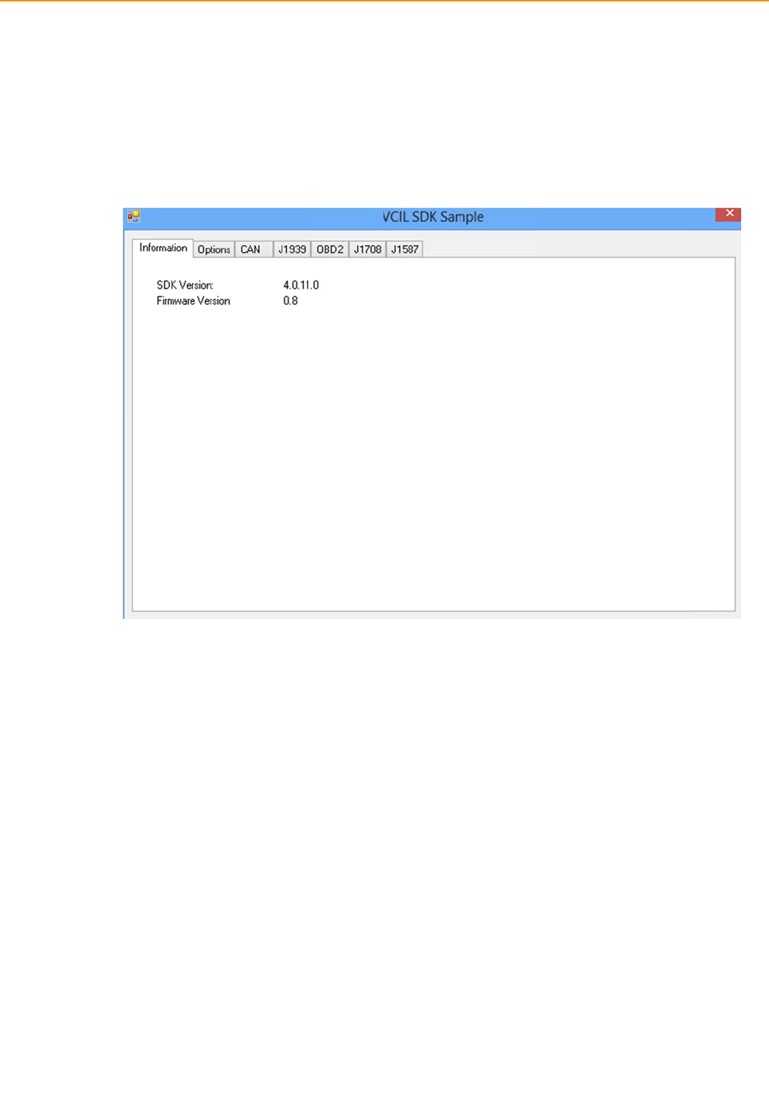
IVU-
4
4.3.
Inthi
s
4
000 User
M
2 Infor
m
s
page,the
d
M
anual
m
ation
d
emoapplic
a
a
tionshows
4
thecurrent
4
2
statusandbasicinforma
a
tion.
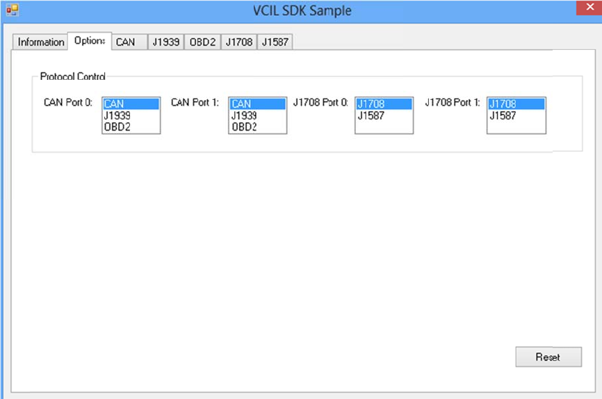
4.3.
Inthi
s
3 Optio
n
s
page,you
c
n
c
anthesettheprotocol
foreachpo
r
r
t.
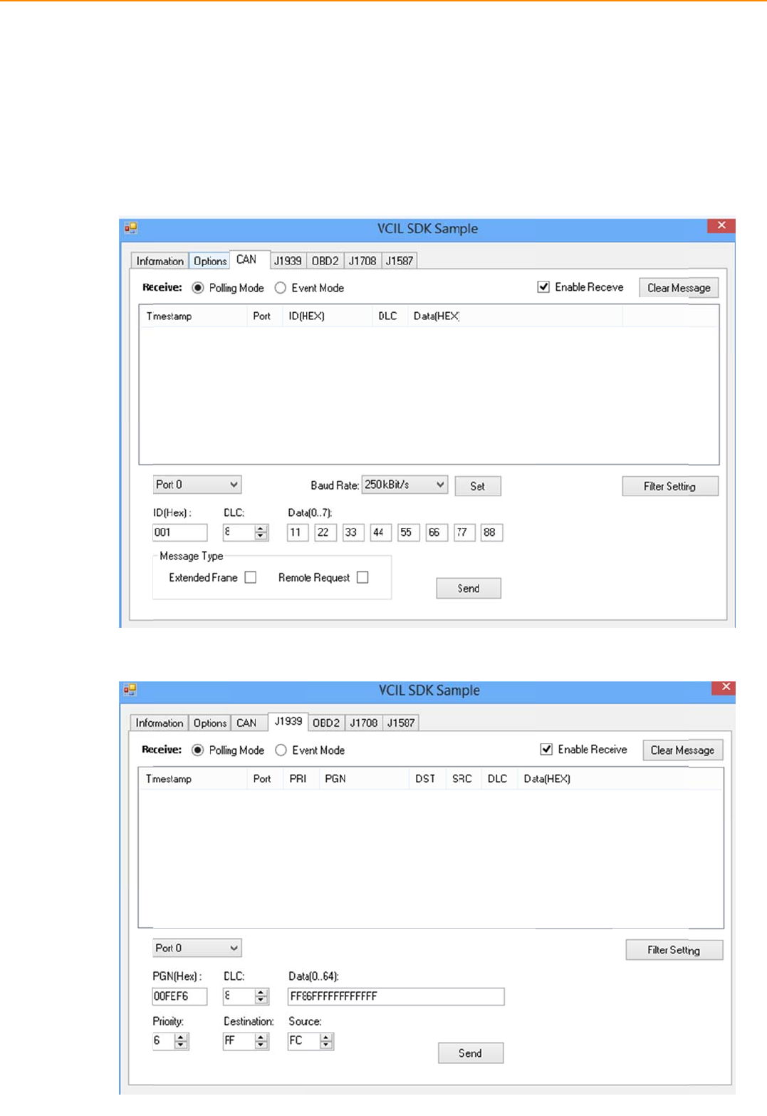
IVU-
4
4.3.
Tous
switc
detai
l
4
000 User
M
4 CAN /
eCAN/J19
3
htothepag
litems.
M
anual
J1939 /
O
3
9/OBD2/
J
eofspecific
O
BD2 / J
J
1708/J158
protocol,th
4
J
1708 / J
1
8
7protocol
o
enyoucan
s
4
4
1
587
o
neachport
,
s
end/readm
pleaseclick
essageons
p
k
oncorresp
o
p
ecificport
b
o
ndingtabt
o
b
ysettingth
e
o
e
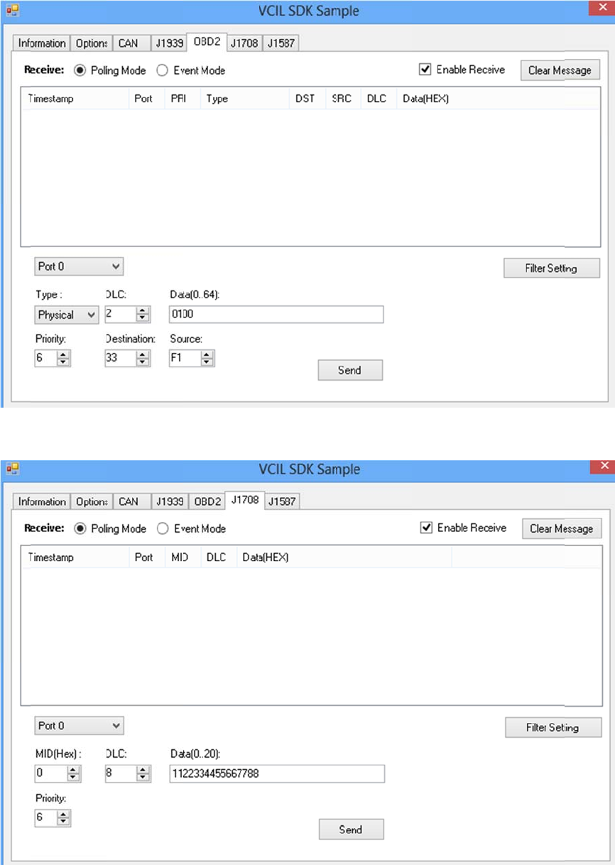
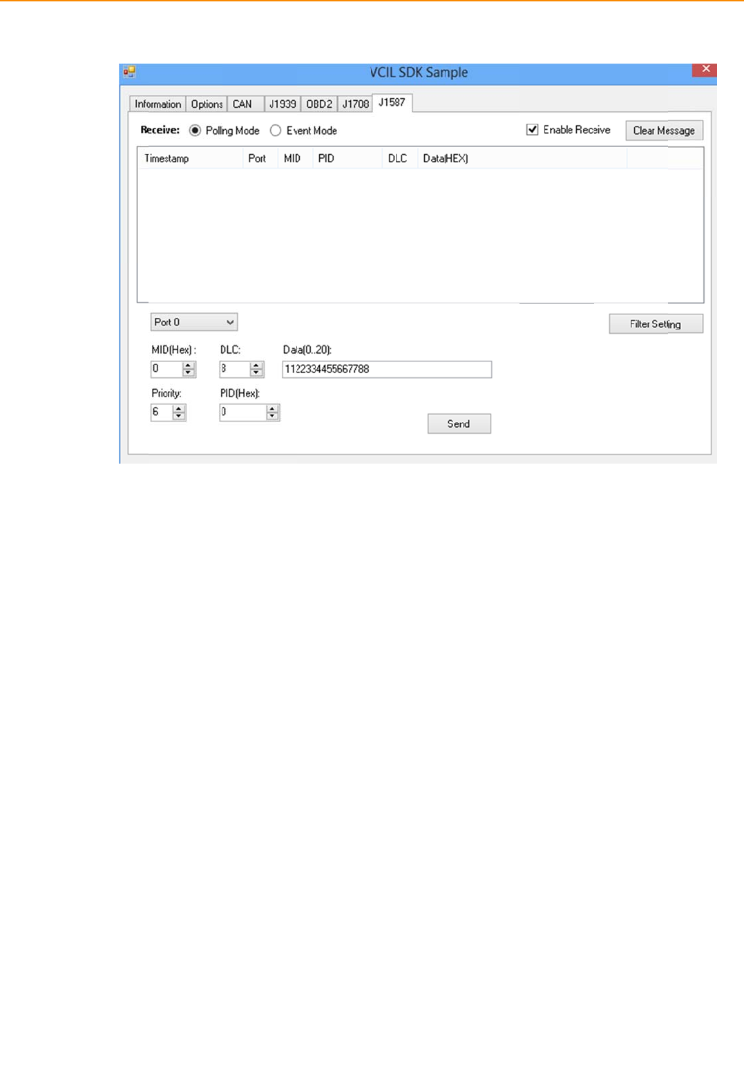
IVU-
4
4.
4
Thes
light
w
toco
n
4.4.
Inthi
s
4
000 User
M
4
Sm
a
martdispla
y
w
eightinter
f
n
trolthefo
n
1 Infor
m
s
page,the
d
M
anual
a
rtD
i
y
demonstra
t
f
acebetwee
n
n
t‐enddispla
m
ation
d
emoapplic
a
i
spla
y
t
ionapplica
t
n
OS(Opera
t
y,backlight
a
tionshows
4
y
De
m
t
iondemons
t
t
ingsystem)
setting,hot
k
thecurrent
4
6
m
ons
t
t
ratetheus
a
andSDP(S
m
k
ey,periphe
r
statusandb
t
rati
o
a
geofMRM
m
artDisplay
r
alcontrol,
e
asicinforma
o
n
SDPAPIwh
i
Co‐Process
o
e
tc.
a
tion.
i
chisa
o
r)allowuser
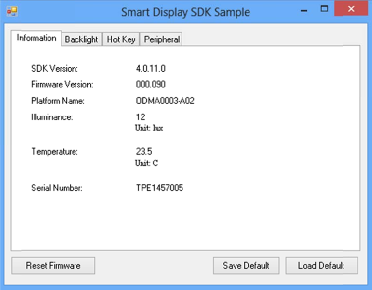
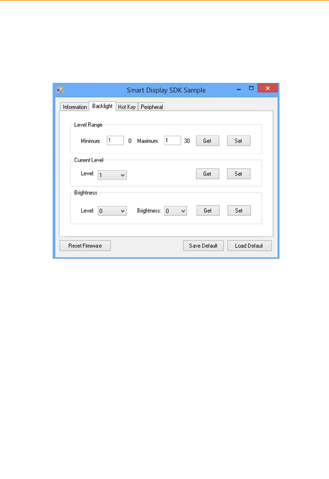
IVU-
4
4.4.
Inthi
s
brigh
t
4
000 User
M
2 Backli
g
s
page,you
c
t
nesslevel.
M
anual
g
ht
c
ansetthel
e
e
velsforba
c
4
c
klight,the
b
4
8
b
rightnessforeachlevel
a
andthecur
r
r
ent
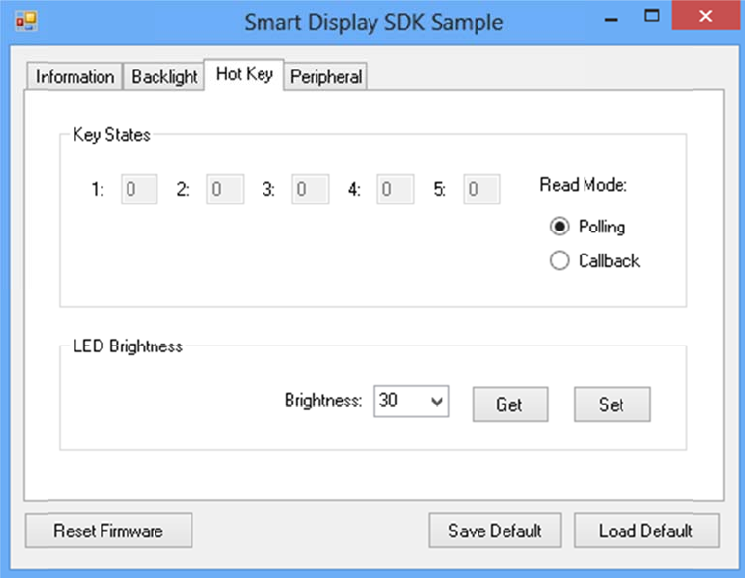
4.4.
Inthi
s
3 Hot k
e
s
page,you
c
e
y
c
anmonitorthepressst
a
ateofeach
h
h
otkeyand
s
s
ettheLED
b
b
rightnesso
f
f
thehotke
y
y
s.
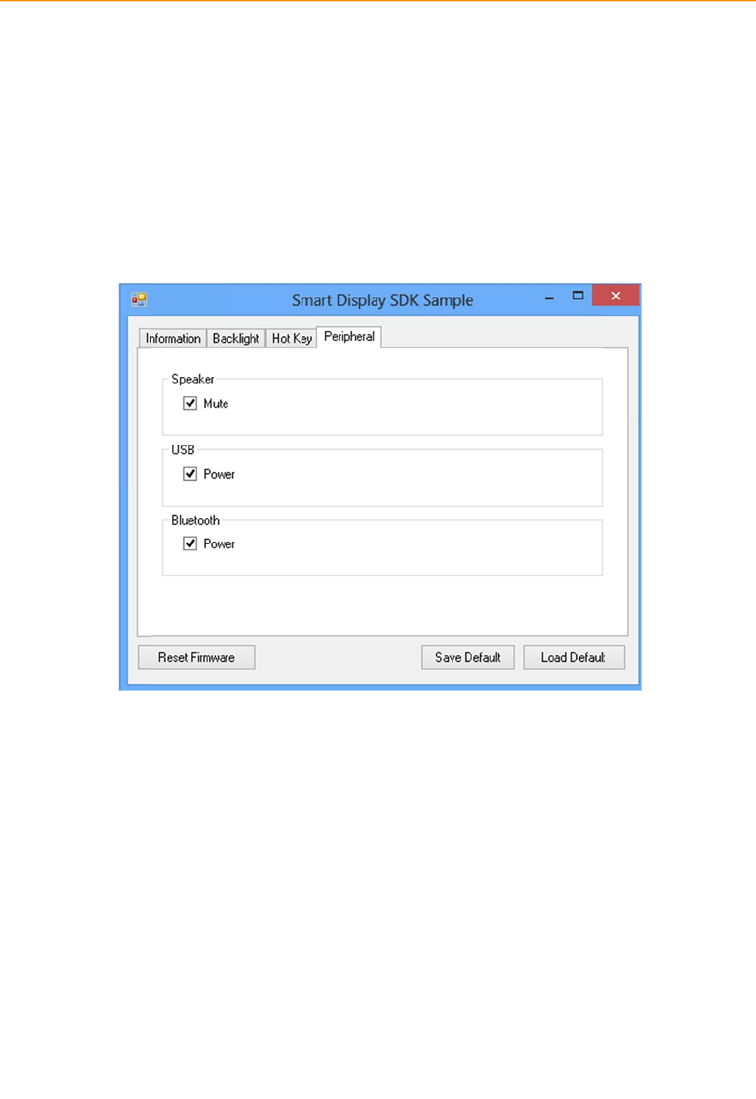
IVU-
4
4.4.
Inthi
s
4
000 User
M
4 Perip
h
s
page,you
c
Speaker
Enable/disa
b
USB
Enable/disa
b
Bluetooth
Enable/disa
b
M
anual
h
eral
c
ancontrol
t
b
lespeaker
v
b
lepowero
f
b
lepowero
f
t
hestatusof
v
olume.
f
Rear‐end
U
f
theBlueto
o
5
f
peripheral
d
U
SBport.
o
thfunction
5
0
d
evices.
builtinMD
T
T
system.
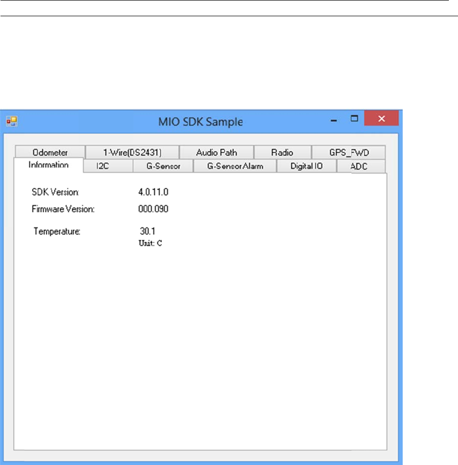
4.
5
The
M
MIO
A
toea
s
The
G
inter
f
4.5.
5
Mult
i
M
IO(Multi‐p
A
PIwhichis
a
s
ilycontrol
G
PSdemons
t
f
acebetwee
n
1 Infor
m
Inthi
i
‐pur
p
urposeInpu
a
lightweigh
t
Multi‐purpo
t
rationappli
c
n
OS(Opera
t
m
ation
spage,the
d
p
oseI
n
t
Output)d
e
t
interfaceb
e
seInputOu
t
c
ationdem
o
t
ingsystem)
d
emoapplic
a
n
putO
u
e
monstratio
e
tweenOS(
t
putsetting
(
o
nstratethe
andGPSm
o
a
tionshows
u
tput
napplicatio
n
Operatings
y
(
Ex:Odome
t
usageofM
R
o
duleallows
thecurrent
Demo
n
demonstra
y
stem)and
M
er,I2C,Audi
R
MGPSAPI
w
usertoeasi
l
s
tatusandb
nstra
t
a
tetheusag
e
M
IOmodule
i
o,Radio,G
P
w
hichisalig
lygetGPSi
n
b
asicinform
a
t
ion
e
ofMRM
allowsuser
P
Sandetc.).
htweight
n
formation.
a
tion.
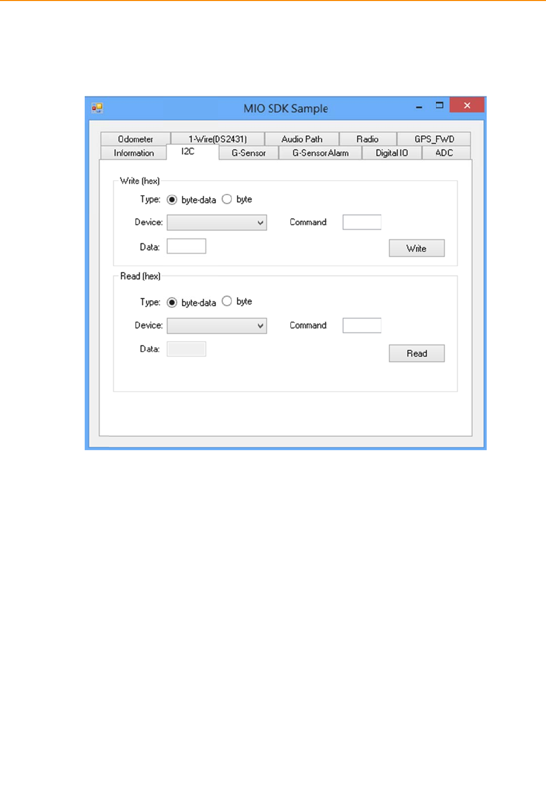
IVU-
4
4.5.
4.5.
Inthi
s
4
000 User
M
2 I2C
3 G-Sen
s
s
page,you
c
M
anual
s
or
c
anetresol
u
u
tionandge
t
5
t
valueofG‐
5
2
sensor
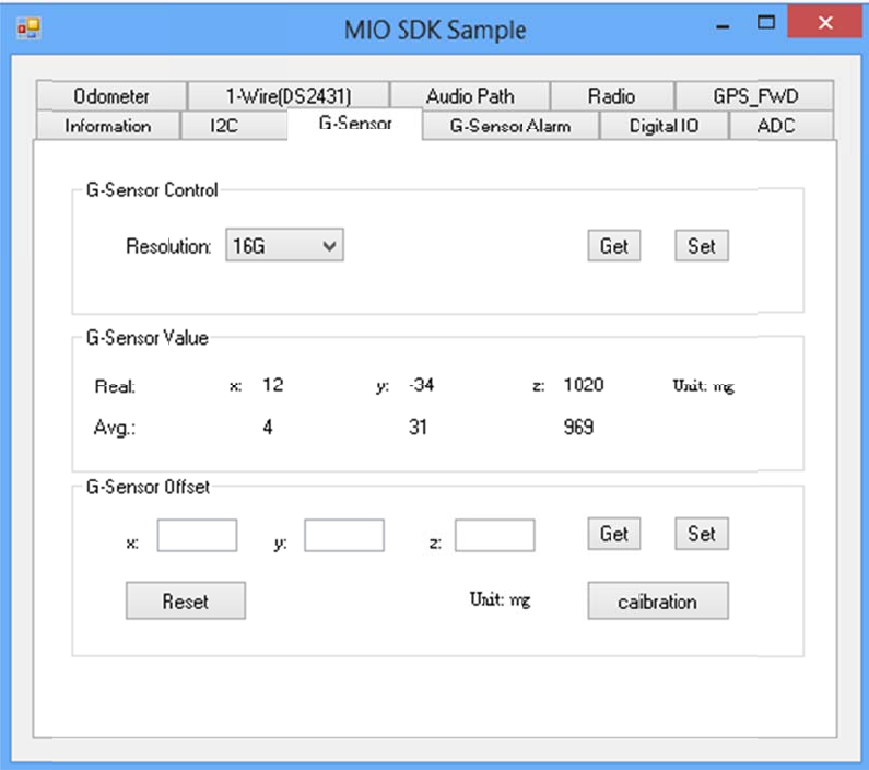
4.5.
Inthi
s
sens
o
whe
n
4 G-Sen
s
s
page,you
c
o
ralarm(20
0
n
thetarget
m
s
or Alar
m
c
anenable/
d
0
0mgto160
m
achinerec
e
m
d
isablethe
G
00mg).Wh
e
e
ivesgreate
r
G
‐sensorAla
r
e
nyouenabl
e
r
thanalarm
r
mfunction
a
e
thealarm
f
threshold.
a
ndsetthe
t
f
unction,yo
u
t
hresholdto
u
canseeth
e
triggerG‐
e
alarmvalu
e
e
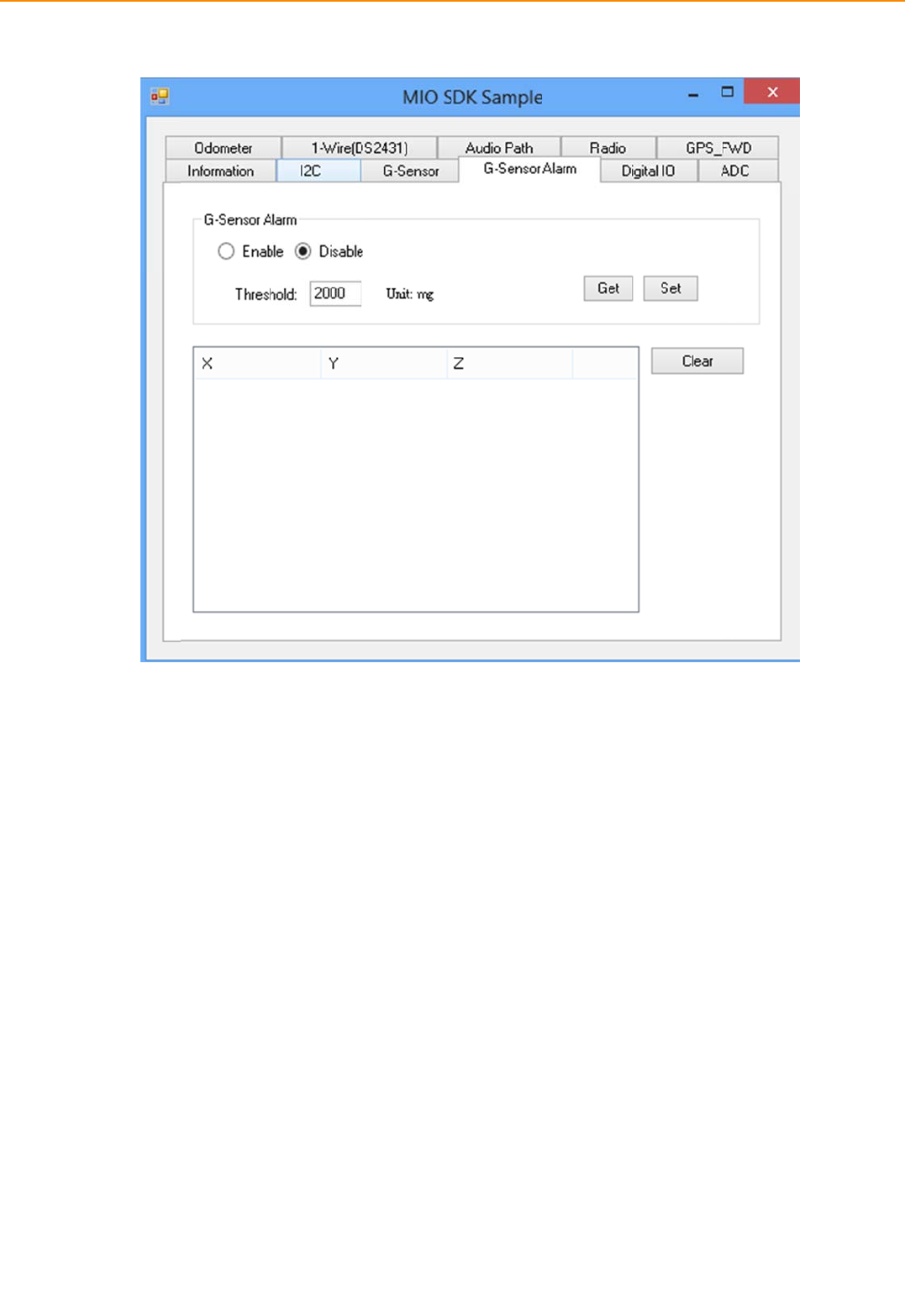
IVU-
4
4.5.
Inthi
s
DI1d
4
000 User
M
5 Digital
s
page,you
c
efaultisnor
M
anual
IO
c
anmonitor
maldigitali
n
thedigitali
n
n
putandca
n
5
n
putstatus
a
n
besetasd
e
5
4
a
ndenable/
d
e
dicatedrev
d
isabledigit
a
e
rsesignali
n
a
loutput.
n
put.
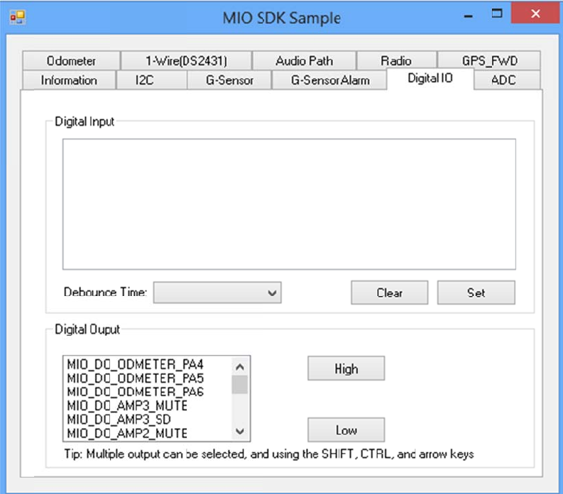
4.5.
Inthi
s
6 ADC
s
page,you
c
c
anreadthe
s
pecificanal
o
o
gtodigitalsi
g
g
nalvalueof
i
nternalMIC
o
o
rExternalM
I
I
C..
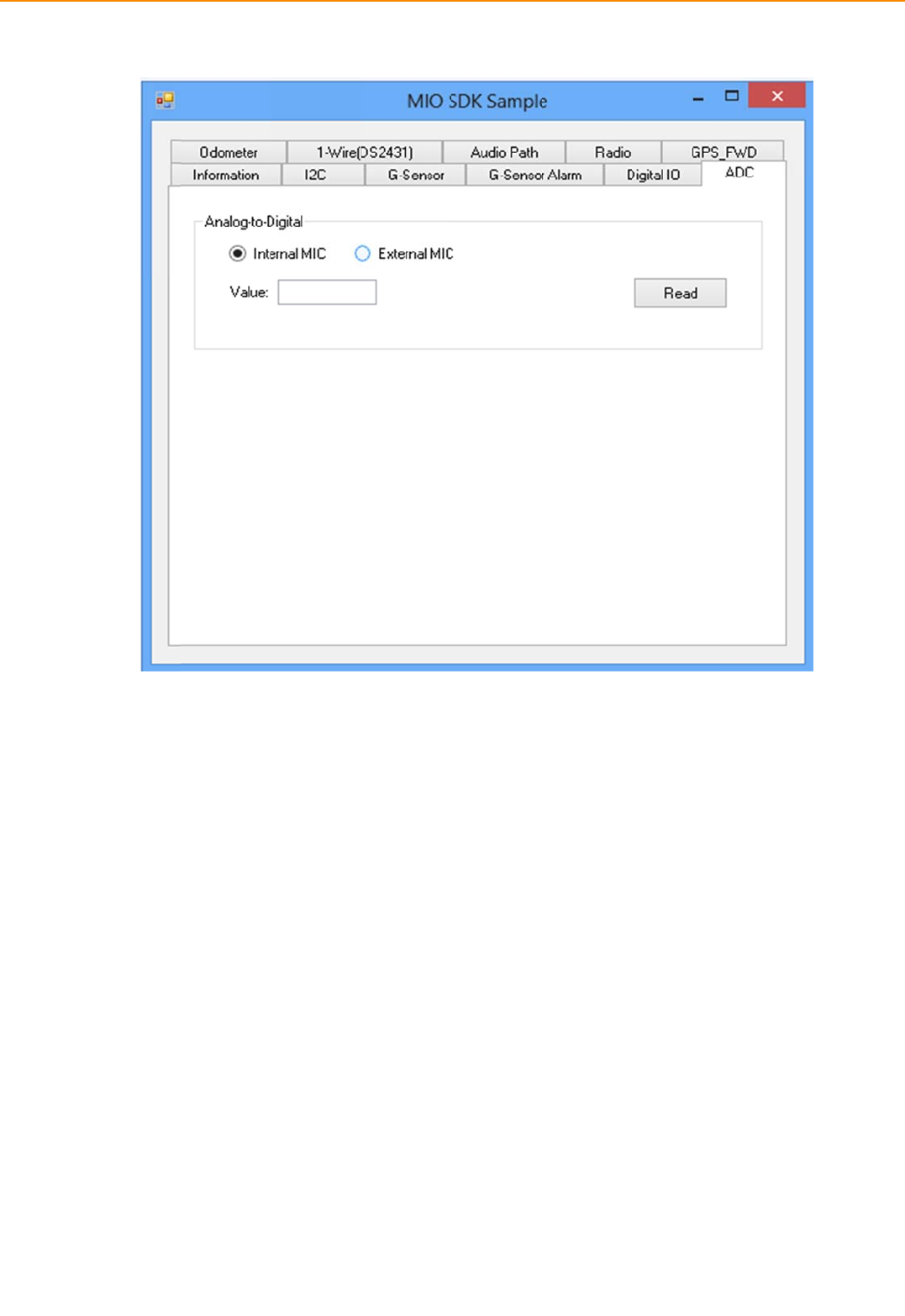
IVU-
4
4.5.
Inthi
s
value
4
000 User
M
7 Odom
e
s
page,you
c
forcontrollin
M
anual
e
ter
c
anreadand
gvehiclestat
cleartheod
o
u
s.
5
o
metervalue.
5
6
Inaddition,
y
oualsocans
e
e
ttheodome
ter’sthreshold
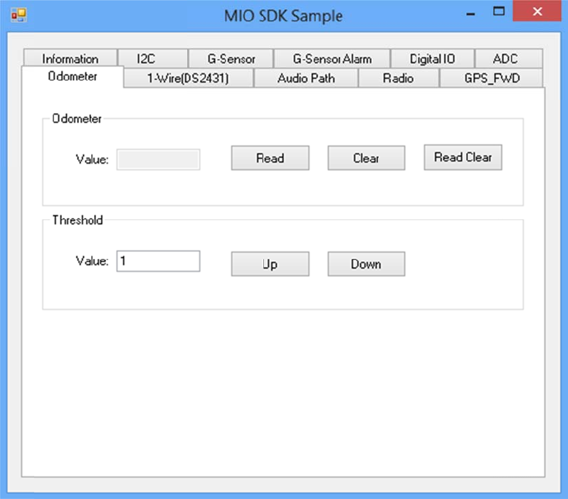
4.5.
Inthi
s
8 1-Wir
e
s
page,you
c
e
(DS243
1
c
anread/wr
1
)
i
te1_wireE
E
E
PROM(DS
2
2
431)IDandEEPROMda
ta.
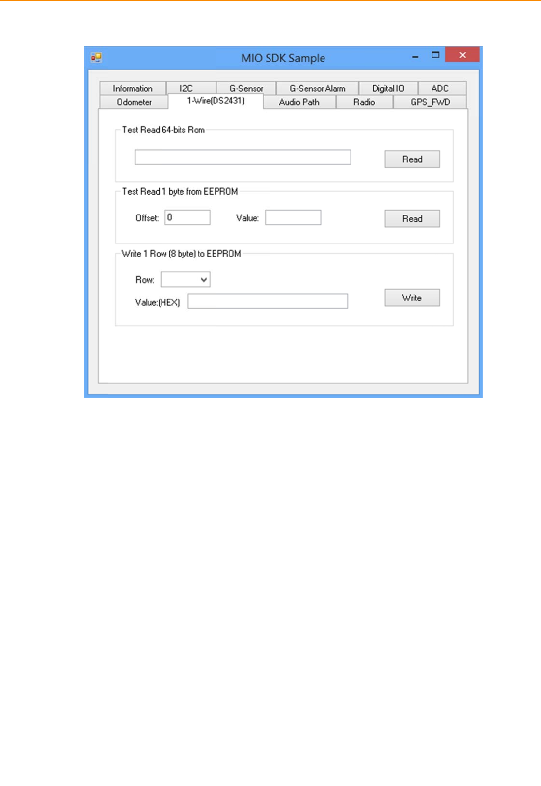
IVU-
4
4.5.
Inthi
s
4
000 User
M
9 Audio
s
page,you
c
M
anual
Path
c
ansetthe
a
a
udiovaluef
5
f
oreachaud
i
5
8
i
opath,andchecktheb
e
e
haviorfor
e
e
achsetting.
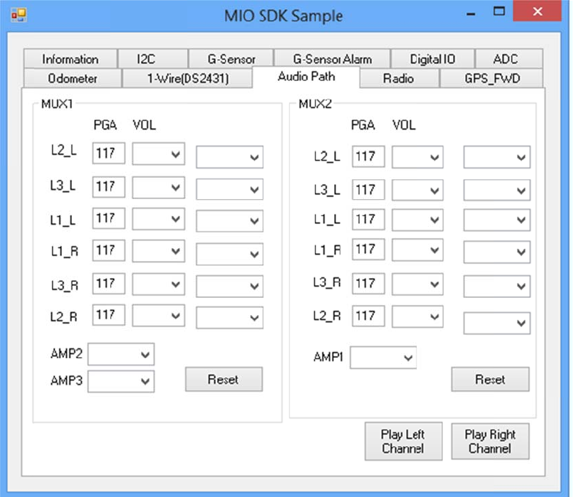
4.5.
Inthi
s
10 Radi
o
s
page,you
c
o
c
anread/se
t
t
theradioI/
/
OandGPS
F
F
WDfunctio
n
n
s.
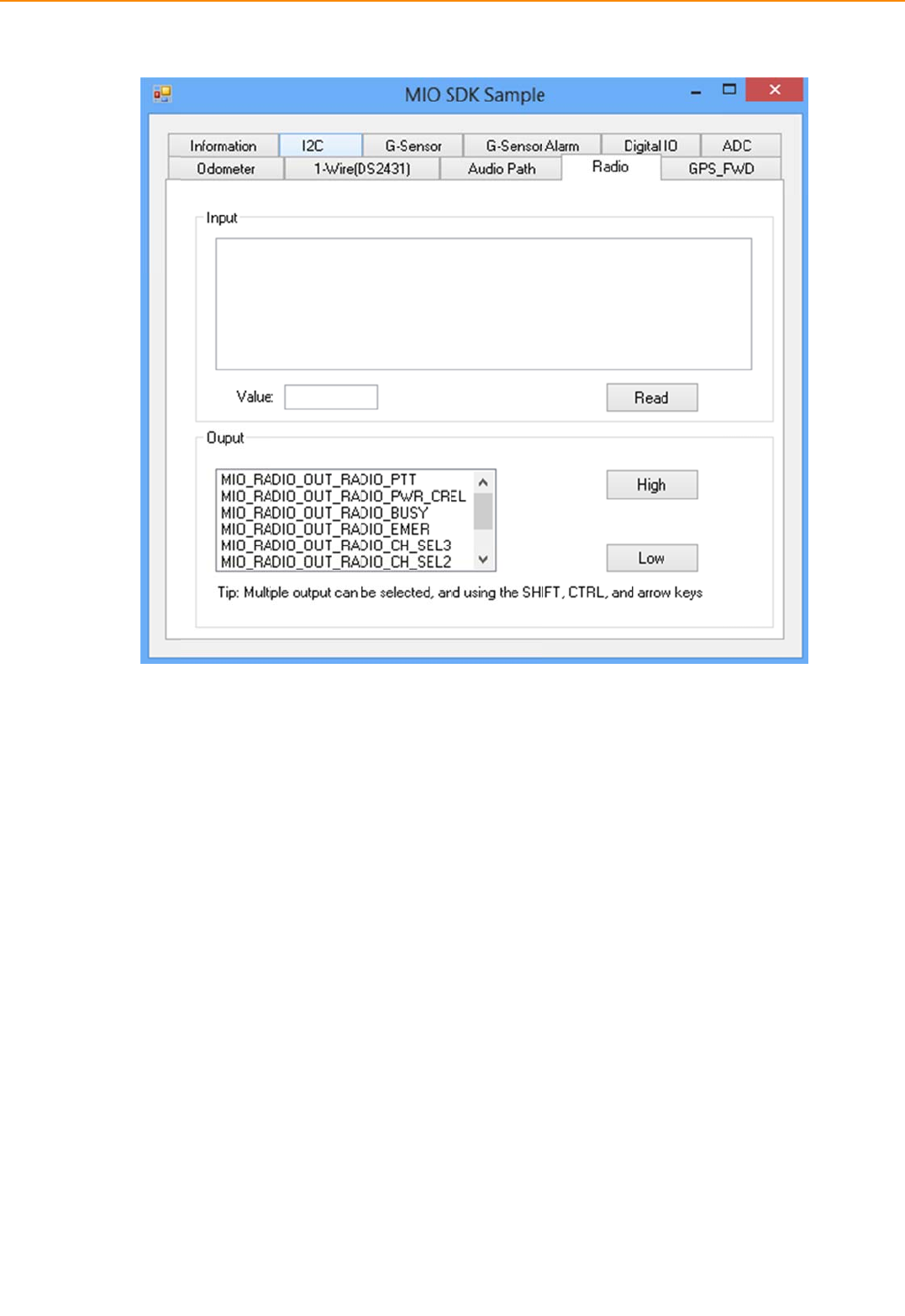
IVU-
4
4.5.
Inthi
s
vehic
4
000 User
M
11 GPS
_
s
page,you
c
lebythats
p
M
anual
_
FWD
c
ansetthe
s
p
ecificDIpin
.
pecificDIpi
n
.
6
n
mappingt
o
6
0
o
GPSFWD,
t
hiswilllink
GPSFWDsi
g
g
nalto
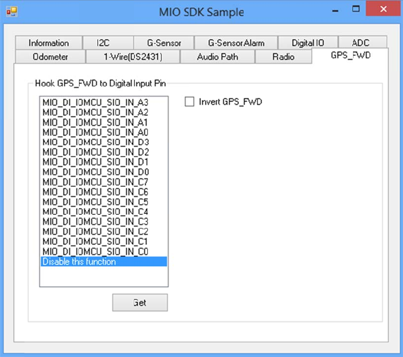

IVU-4000 User Manual 62
Appendix A
A MDT
This appendix explains the MDT
detailed information.

63 TREK-688 User Manual
A.1MDT Specifications
MDT Specifications
Display
Model MDT
Design Compatible Models Paired with IVU 4000
Resolution 1024*768
Brightness (cd/m2)1000 (typical) without touchscreen
Viewing Angle -80° ~80° (H) / -80° ~80° (V)
Lamp Life (hrs) 10,000hrs (TYP. @IF=120mA, Ta=25℃)
Lamp type LED
Touchscreen Touchscreen Resistive, 5-Wire, Anti-glare
Front
plane
Speaker 2 watts
Hotkeys Supports 5 hotkeys (user defined)
Brightness Control Light sensing (default), manually controlled
by button (optional)
Back plane
USB Port X2
MDT Port (DVI-I) X1
Mic in X1
Rest Button X1
Power DC input 15V± 5%
Power Consumption(Max.) 16W
Mechanical
Mounting Design compatible with RAM mount
Material PC+ABS
Weight 4.3 lbs
Dimension 9.53” x 11.1”x 1.85" inch
IP Rating IP55
Environment
Operating Temperature -30 to 65°C
Storage Temperature -40 to 85°C
Vibration MIL-STD-810G
Note:TheBrightnesscontrolisadjustedbytheautolightsensorinthefrontpanelasdefault;itisalso
definedbybuttononthefrontpanelbymanual.
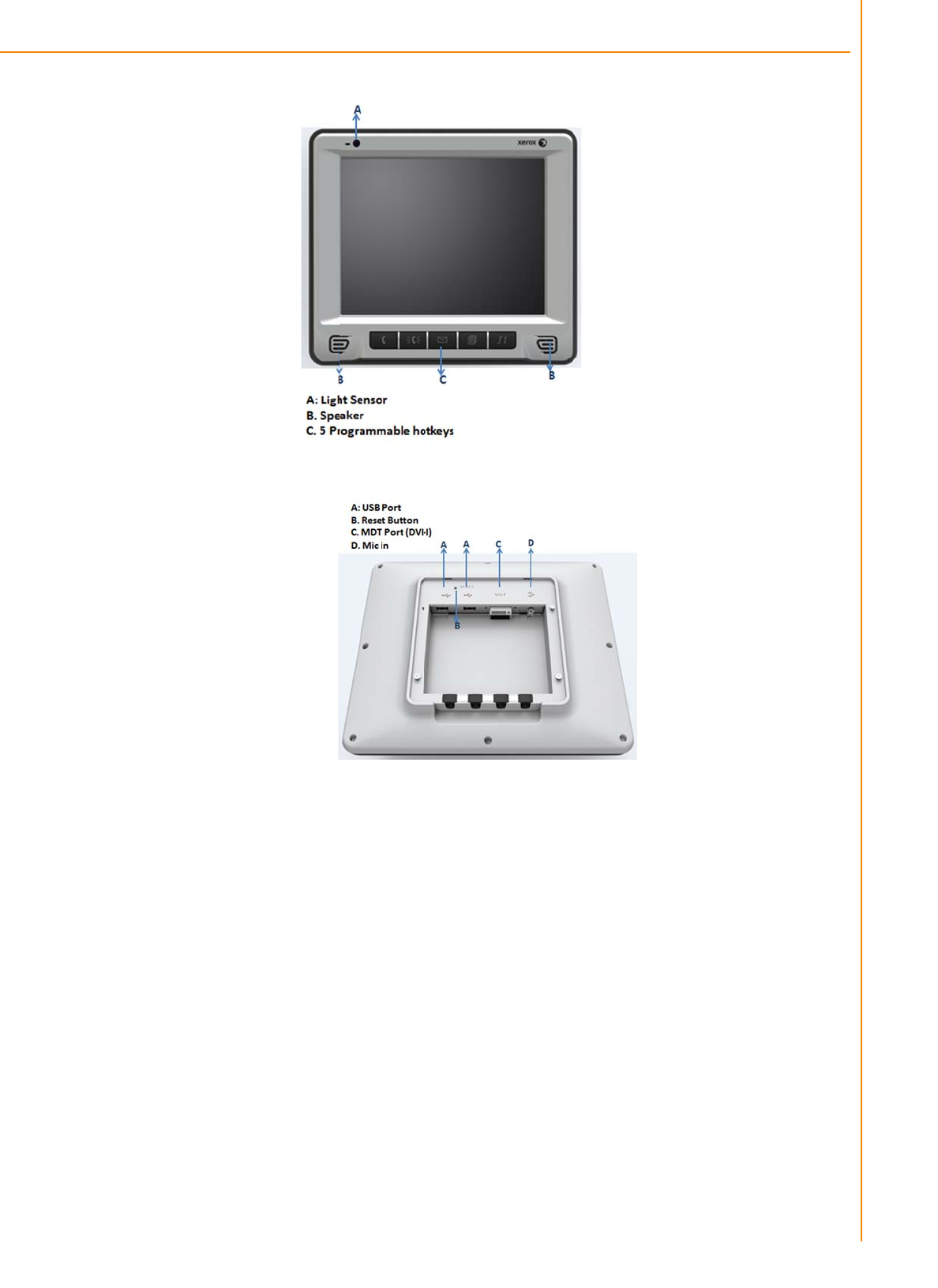
TRE
K
K
-688 User
M
M
anual
Figure A
Figure A
.
1 MDT Fron
t
.
2 MDT Rear
6
t
View
View
6
4
Appendix A MDT-1000

65 TREK-688 User Manual
www.Xerox.com
Please verify specifications before quoting. This guide is intended for reference
purposes only.
All product specifications are subject to change without notice.
No part of this publication may be reproduced in any form or by any means,
electronic, photocopying, recording or otherwise, without prior written permis-
sion of the publisher.
All brand and product names are trademarks or registered trademarks of their
respective companies.
© Xerox Co., Ltd. 2010