Advantech Co MARS-3070 Tablet PC User Manual Verdict D7
Advantech Co Ltd Tablet PC Verdict D7
User manual

MARS-3070
Tablet PC

Copyright
The documentation and the software included with this product are copyrighted 2007 by Advantech
Co., Ltd. All rights are reserved. Advantech Co., Ltd. reserves the right to make improvements in the
products described in this manual at any time without notice. No part of this manual may be
reproduced, copied, translated or transmitted in any form or by any means without the prior written
permission of Advantech Co., Ltd. Information provided in this manual is intended to be accurate and
reliable. However, Advantech Co., Ltd. assumes no responsibility for its use, nor for any infringements
of the rights of third parties, which may result from its use.
Acknowledgements
Intel and Pentium are trademarks of Intel Corporation.
Microsoft Windows and MS-DOS are registered trademarks of Microsoft Corp.
All other product names or trademarks are properties of their respective owners.
Product Warranty (2 years)
Advantech warrants to you, the original purchaser, that each of its products will be free from defects in
materials and workmanship for two years from the date of purchase.
This warranty does not apply to any products which have been repaired or altered by persons other
than repair personnel authorized by Advantech, or which have been subject to misuse, abuse,
accident or improper installation. Advantech assumes no liability under the terms of this warranty as a
consequence of such events.
Because of Advantech‘s high quality-control standards and rigorous testing, most of our customers
never need to use our repair service. If an Advantech product is defective, it will be repaired or
replaced at no charge during the warranty period. For out-of-warranty repairs, you will be billed
according to the cost of replacement materials, service time and freight. Please consult your dealer
for more details.
If you think you have a defective product, follow these steps:
1 Collect all the information about the problem encountered. (For example, CPU speed, Advantech
products used, other hardware and software used, etc.) Note anything abnormal and list any onscreen
messages you get when the problem occurs.
2 Call your dealer and describe the problem. Please have your manual, product, and any helpful
information readily available.
3 If your product is diagnosed as defective, obtain an RMA (return merchandise authorization) number
from your dealer. This allows us to process your return more quickly.
4 Carefully pack the defective product, a fully-completed Repair and Replacement Order Card and a
photocopy proof of purchase date (such as your sales receipt) in a shippable container. A product returned
without proof of the purchase date is not eligible for warranty service.
5 Write the RMA number visibly on the outside of the package and ship it prepaid to your dealer.
Part No. 2006310002 Edition 3 Printed in Taiwan April 2008
Declaration of Conformity
CE
This product has passed the CE test for environmental specifications when shielded cables are used for
external wiring. We recommend the use of shielded cables. This kind of cable is available from Advantech.
Please contact your local supplier for ordering information.
CE
This product has passed the CE test for environmental specifications. Test conditions for passing included the
equipment being operated within an industrial enclosure. In order to protect the product from being damaged
by ESD (Electrostatic Discharge) and EMI leakage, we strongly recommend the use of CE-compliant industrial
enclosure products.
FCC Class B
Note: This equipment has been tested and found to comply with the limits for a Class B digital device,
pursuant to part 15 of the FCC Rules. These limits are designed to provide reasonable protection against
harmful interference in a residential installation. This equipment generates, uses and can radiate radio
frequency energy and, if not installed and used in accordance with the instructions, may cause harmful
interference to radio communications. However, there is no guarantee that interference will not occur in a
particular installation. If this equipment does cause harmful interference to radio or television reception, which
can be determined by turning the equipment off and on, the user is encouraged to try to correct the
interference by one or more of the following measures:
¢ Reorient or relocate the receiving antenna.
¢ Increase the separation between the equipment and receiver.
¢ Connect the equipment into an outlet on a circuit different from that to which
the
receiver is connected.
¢ Consult the dealer or an experienced radio/TV technician for help.
Europe œ EU Declaration of Conformity
This device complies with the essential requirements of the R&TTE Directive 1999/5/EC. The
following test methods have been applied in order to prove presumption of conformity with the
essential requirements of the R&TTE Directive 1999/5/EC:
EN 60950-1: 2001
Safety of information technology equipment
IEEE Std. 1528: 2003
Recommended practice for determining the peak spatial-average specific absorption rate
(SAR) in the human head from wireless communications devices: Measurement Techniques.
ANSI/IEEE C95.3: 2002
IEEE recommended practice for the measurement and computations of radio frequency
electromagnetic fields with respect to human exposure to such fields, 100kHz-300GHz.
EN 300 328 V1.7.1 (2006-10)
Electromagnetic compatibility and Radio spectrum Matters (ERM); Wideband transmission systems;
Data transmission equipment operating in the 2,4 GHz ISM band and using wide band modulation
techniques; Harmonized EN covering essential requirements under article 3.2 of the R&TTE Directive
EN 301 893 V1.2.3 (2003-08)
Broadband Radio Access Networks (BRAN); 5 GHz high performance RLAN; Harmonized EN
covering essential requirements of article 3.2 of the R&TTE Directive
2005/513/EC, Commission Decision of 11 July 2005 on the harmonised use
of radio spectrum in the 5 GHz frequency band for the implementation of wireless access systems
including radio local area networks (WAS/RLANs)
EN 301 489-17 V1.2.1 (2002-08) and EN 301 489-1 V1.4.1 (2002-08)
Electromagnetic compatibility and Radio spectrum Matters (ERM); ElectroMagnetic
Compatibility (EMC) standard for radio equipment and services; Part 17: Specific conditions
for 2,4 GHz wideband transmission systems and 5 GHz high performance RLAN equipment
This device is a 2.4 GHz wideband transmission system (transceiver), intended for use in all EU
member states and EFTA countries under the following conditions and/or with the following
restrictions:
In Italy the end-user should apply for a license at the national spectrum authorities in order to
obtain authorization to use the device for setting up outdoor radio links and/or for supplying
public access to telecommunications and/or network services.
This device may not be used for setting up outdoor radio links in France and in some areas the RF
output power may be limited to 10 mW EIRP in the frequency range of 2454 œ 2483.5 MHz. For
detailed information the end-user should contact the national spectrum authority in France.

Cesky [Czech] [Advantech] tímto prohlaáuje, _e tento [MARS-3070] je ve shodì se základními po_adavky a daláími pøísluánðmi
ustanoveními smìrnice 1999/5/ES.
Dansk [Danish] Undertegnede [Advantech] erklærer herved, at følgende udstyr [MARS-3070] overholder de væsentlige krav og
øvrige relevante krav i direktiv 1999/5/EF.
Deutsch [German] Hiermit erklärt [Advantech], dass sich das Gerät [MARS-3070] in Übereinstimmung mit den grundlegenden
Anforderungen und den übrigen einschlägigen Bestimmungen der Richtlinie 1999/5/EG befindet.
Eesti [Estonian] Käesolevaga kinnitab [Advantech] seadme [MARS-3070] vastavust direktiivi1999/5/EÜ põhinõuetele ja
nimetatud direktiivist tulenevatele teistele asjakohastele sätetele.
English Hereby, [Advantech], declares that this [MARS-3070] is in compliance with the essential requirements and
other relevant provisions of Directive 1999/5/ EC.
Español [Spanish] Por medio de la presente [Advantech] declara que el [MARS-3070] cumple con los requisitos esenciales y
cualesquiera otras disposiciones aplicables o exigibles de la Directiva 1999/5/CE.
ǼȜȜȘȞȚțȒ [Greek] ȂǼ ȉǾȃ ȆǹȇȅȊȈǹ [Advantech] ?Ǿȁ?ȃǼǿ ȅȉǿ [MARS-3070] ȈȊȂȂȅȇĭ?ȃǼȉǹǿ ȆȇȅȈ ȉǿȈ
ȅȊȈǿ??ǼǿȈ ǹȆǹǿȉǾȈǼǿȈ Ȁǹǿ ȉǿȈ ȁȅǿȆǼȈȈȋǼȉǿȀǼȈ ?ǿǹȉǹȄǼǿȈ ȉǾȈ ȅ?ǾīǿǹȈ 1999/5/ǼȀ.
Français [French] Par la présente [Advantech] déclare que l'appareil [MARS-3070] est con-forme aux exigences essentielles et
aux autres dispositions pertinentes de la directive 1999/5/CE.
Italiano [Italian] Con la presente [Advantech] dichiara che questo [MARS-3070] è conforme ai requisiti essenziali ed alle altre
disposizioni pertinenti stabilite dalla direttiva 1999/5/CE.
Latviski Ar ¦o [Advantech] deklarç, ka [MARS-3070] atbilst Direktîvas 1999/5/EK bûtiskajâm prasîbâm
[Latvian] un citiem ar to saistîtajiem noteikumiem.
Lietuviǐ [Lithuanian] àiuo [Advantech] deklaruoja, kad áis [MARS-3070] atitinka esminius reikalavimus ir kitas 1999/5/EB
Direktyvos nuostatas.
Nederlands [Dutch] Hierbij verklaart [Advantech] dat het toestel [MARS-3070] in overeenstemming is met de essentiële eisen en
de andere relevante bepalingen van richtlijn 1999/5/EG.
Malti [Maltese] Hawnhekk, [Advantech], jiddikjara li dan [MARS-3070] jikkonforma malhtigijiet essenzjali u ma
provvedimenti ohrajn relevanti li hemm fid-Dirrettiva 1999/5/EC.
Magyar [Hungarian] Alulírott, [Advantech] nyilatkozom, hogy a [MARS-3070] megfelel a vonatkozó alapvetõ követelményeknek és
az 1999/5/EC irányelv egyéb elõírásainak.
Polski [Polish] Niniejszym [Advantech] oŒwiadcza, ¿e [MARS-3070] jest zgodny z zasadniczymi wymogami oraz
pozosta¹ymi stosownymi postanowieniami Dyrektywy 1999/5/EC.
Português [Portuguese] [Advantech] declara que este [MARS-3070] está conforme com os requisitos essenciais e outras disposições
da Directiva 1999/5/CE.
Slovensko [Slovenian] [Advantech] izjavlja, da je ta [tip opreme] v skladu z bistvenimi zahtevami in ostalimi relevantnimi doloèili
direktive 1999/5/ES.
Slovensky [Slovak] [Advantech] tðmto vyhlasuje, _e [tip opreme] spåòa základné po_iadavky a váetky prísluáné ustanovenia
Smernice 1999/5/ES.
Suomi [Finnish] [Advantech] vakuuttaa täten että [tip opreme] tyyppinen laite on direktiivin 1999/5/EY oleellisten
vaatimusten ja sitä koskevien direktiivin muiden ehtojen mukainen.
Svenska [Swedish] Härmed intygar [Advantech] att denna [tip opreme] står I överensstämmelse med de väsentliga
egenskapskrav och övriga relevanta bestämmelser som framgår av direktiv 1999/5/EG.

Technical Support and Assistance
1 Visit the Advantech web site at www.advantech.com/support where you can find the latest
information about the product.
2 Contact your distributor, sales representative, or Advantech's customer service center for technical
support if you need additional assistance. Please have the following information ready before you call:
œ Product name and serial number
œ Description of your peripheral attachments
œ Description of your software (operating system, version, application software,
etc.)
œ A complete description of the problem
œ The exact wording of any error messages
Warnings, Cautions and Notes
Warning! Warnings indicate conditions, which if not observed, can cause personal injury!
Caution! Cautions are included to help you avoid damaging hardware or losing data. e.g. There is a danger
of a new battery exploding if it is incorrectly installed. Do not attempt to recharge, force open, or
heat the battery. Replace the battery only with the same or equivalent type recommended by the
manufacturer. Discard used batteries according to the manufacturer's instructions.
Note! Notes provide optional additional information.
Document Feedback
To assist us in making improvements to this manual, we would welcome comments and constructive
criticism. Please send all such - in writing to: support@advantech.com
Safety Instructions
1 Read these safety instructions carefully.
2 Keep this User Manual for later reference.
3 Disconnect this equipment from any AC outlet before cleaning. Use a damp cloth. Do not use liquid or
spray detergents for cleaning.
4 For plug-in equipment, the power outlet socket must be located near the equipment and must be easily
accessible.
5 Keep this equipment away from humidity.
6 Put this equipment on a reliable surface during installation. Dropping it or letting it fall may cause
damage.
7 The openings on the enclosure are for air convection. Protect the equipment from overheating. DO
NOT COVER THE OPENINGS.
8 Make sure the voltage of the power source is correct before connecting the equipment to the power
outlet.
9 Position the power cord so that people cannot step on it. Do not place anything over the power cord.
10 All cautions and warnings on the equipment should be noted.
11 If the equipment is not used for a long time, disconnect it from the power source to avoid damage by
transient over-voltage.
12 Never pour any liquid into an opening. This may cause fire or electrical shock.
13 Never open the equipment. For safety reasons, the equipment should be opened only by qualified
service personnel.
14 If one of the following situations arises, get the equipment checked by service personnel:
15 The power cord or plug is damaged.
16 Liquid has penetrated into the equipment.
17 The equipment has been exposed to moisture.
18 The equipment does not work well, or you cannot get it to work according to the user's manual.
19 The equipment has been dropped and damaged.
20 The equipment has obvious signs of breakage.
21 DO NOT LEAVE THIS EQUIPMENT IN AN ENVIRONMENT WHERE THE STORAGE
TEMPERATURE MAY GO BELOW -10° C (-4° F) OR ABOVE 55° C (140° F). THIS COULD DAMAGE THE
EQUIPMENT. THE EQUIPMENT SHOULD BE IN A CONTROLLED ENVIRONMENT.
22 CAUTION: DANGER OF EXPLOSION IF BATTERY IS INCORRECTLY REPLACED. REPLACE ONLY
WITH THE SAME OR EQUIVALENT TYPE RECOMMENDED BY THE MANUFACTURER, DISCARD USED
BATTERIES ACCORDING TO THE MANUFACTURER'S INSTRUCTIONS.
23 The sound pressure level at the operator's position according to IEC 704-1:1982
is no more than 70 dB (A). DISCLAIMER: This set of instructions is given according to IEC 704-1.
Advantech disclaims all responsibility for the accuracy of any statements contained herein.
Wichtige Sicherheishinweise
1 Bitte lesen sie Sich diese Hinweise sorgfältig durch.
2 Heben Sie diese Anleitung für den späteren Gebrauch auf.
3 Vor jedem Reinigen ist das Gerät vom Stromnetz zu trennen. Verwenden Sie Keine Flüssig-oder
Aerosolreiniger. Am besten dient ein angefeuchtetes Tuch zur Reinigung.
4 Die NetzanschluBsteckdose soll nahe dem Gerät angebracht und leicht zugänglich sein.
5 Das Gerät ist vor Feuchtigkeit zu schützen.
6 Bei der Aufstellung des Gerätes ist auf sicheren Stand zu achten. Ein Kippen oder Fallen könnte
Verletzungen hervorrufen.
7 Die Belüftungsöffnungen dienen zur Luftzirkulation die das Gerät vor überhitzung schützt. Sorgen Sie
dafür, daB diese Öffnungen nicht abgedeckt werden.
8 Beachten Sie beim. AnschluB an das Stromnetz die AnschluBwerte.
9 Verlegen Sie die NetzanschluBleitung so, daB niemand darüber fallen kann. Es sollte auch nichts auf
der Leitung abgestellt werden.
10 Alle Hinweise und Warnungen die sich am Geräten befinden sind zu beachten.
11 Wird das Gerät über einen längeren Zeitraum nicht benutzt, sollten Sie es vom Stromnetz trennen.
Somit wird im Falle einer Überspannung eine Beschädigung vermieden.
12 Durch die Lüftungsöffnungen dürfen niemals Gegenstände oder Flüssigkeiten in das Gerät gelangen.
Dies könnte einen Brand bzw. elektrischen Schlag auslösen.
13 Öffnen Sie niemals das Gerät. Das Gerät darf aus Gründen der elektrischen Sicherheit nur von
authorisiertem Servicepersonal geöffnet werden.
14 Wenn folgende Situationen auftreten ist das Gerät vom Stromnetz zu trennen und von einer
qualifizierten Servicestelle zu überprüfen:
15 Netzkabel oder Netzstecker sind beschädigt.
16 Flüssigkeit ist in das Gerät eingedrungen.
17 Das Gerät war Feuchtigkeit ausgesetzt.

18 Wenn das Gerät nicht der Bedienungsanleitung entsprechend funktioniert oder Sie mit Hilfe dieser
Anleitung keine Verbesserung erzielen.
19 Das Gerät ist gefallen und/oder das Gehäuse ist beschädigt.
20 Wenn das Gerät deutliche Anzeichen eines Defektes aufweist.
21 VOSICHT: Explisionsgefahr bei unsachgemaben Austausch der Batterie.Ersatz nur durch densellben
order einem vom Hersteller empfohlene-mahnlichen Typ. Entsorgung gebrauchter Batterien navh Angaben
des Herstellers.
22 ACHTUNG: Es besteht die Explosionsgefahr, falls die Batterie auf nicht fachmännische Weise
gewechselt wird. Verfangen Sie die Batterie nur gleicher oder entsprechender Type, wie vom Hersteller
empfohlen. Entsorgen Sie Batterien nach Anweisung des Herstellers.
23 Der arbeitsplatzbezogene Schalldruckpegel nach DIN 45 635 Teil 1000 beträgt 70dB(A) oder weiger.
Haftungsausschluss: Die Bedienungsanleitungen wurden entsprechend der IEC704-1 erstellt. Advantech lehnt
jegliche Verantwortung für die Richtigkeit der in diesem Zusammenhang getätigten Aussagen ab.
Safety Precaution - Static Electricity
Follow these simple precautions to protect yourself from harm and the products from damage.
¢ To avoid electrical shock, always disconnect the power from your PC chassis before you work
on it. Don't touch any components on the CPU card or other cards while the PC is on.
¢ Disconnect power before making any configuration changes. The sudden rush of power as you
connect a jumper or install a card may damage sensitive electronic components.
˙˖˖ʳˣ˴̅̇ʳ˄ˈˁ˅˄ʳ˼́˹̂̅̀˴̇˼̂́ʳ˹̂̅ʳ̈̆˸̅
ˬ̂̈ʳ˴̅˸ʳ˶˴̈̇˼̂́˸˷ʳ̇˻˴̇ʳ˶˻˴́˺˸̆ʳ̂̅ʳ̀̂˷˼˹˼˶˴̇˼̂́̆ʳ́̂̇ʳ˸̋̃̅˸̆̆˿̌ʳ˴̃̃̅̂̉˸˷ʳ˵̌ʳ̇˻˸ʳ̃˴̅̇̌ʳ̅˸̆̃̂́̆˼˵˿˸ʳ˹̂̅
˶̂̀̃˿˼˴́˶˸ʳ˶̂̈˿˷ʳ̉̂˼˷ʳ̌̂̈̅ʳ˴̈̇˻̂̅˼̇̌ʳ̇̂ʳ̂̃˸̅˴̇˸ʳ̇˻˸ʳ˸̄̈˼̃̀˸́̇ˁ
˙˖˖ʳ˥˙ʳ˥˴˷˼˴̇˼̂́ʳ˘̋̃̂̆̈̅˸ʳ˦̇˴̇˸̀˸́̇ˍ
˄ˁʳ˧˻˼̆ʳ˧̅˴́̆̀˼̇̇˸̅ʳhas been demonstrated ˶̂ˀ˿̂˶˴̇˸˷ʳcompliace requirements with Bluetooth and WALN.
˅ˁʳ˧˻˼̆ʳ˸̄̈˼̃̀˸́̇ʳ˶̂̀̃˿˼˸̆ʳ̊˼̇˻ʳ˙˖˖ʳ˥˙ʳ̅˴˷˼˴̇˼̂́ʳ˸̋̃̂̆̈̅˸ʳ˿˼̀˼̇̆ʳ̆˸̇ʳ˹̂̅̇˻ʳ˹̂̅ʳ˴́ʳ̈́˶̂́̇̅̂˿˿˸˷
˸́̉˼̅̂́̀˸́̇ˁʳ˧˻˼̆ʳ˷˸̉˼˶˸ʳ̊˴̆ʳ̇˸̆̇˸˷ʳ˹̂̅ʳ̇̌̃˼˶˴˿ʳ˿˴̃ʳ˻˸˿˷ʳ̂̃˸̅˴̇˼̂́̆ʳ̊˼̇˻ʳ̇˻˸ʳ˷˸̉˼˶˸ʳ˶̂́̇˴˶̇˸˷ʳ˷˼̅˸˶̇˿̌ʳʳ̇̂ʳ̇˻˸
˻̈̀˴́ʳ˵̂˷̌ʳ̇̂ʳ̇˻˸ʳ˵˴˶˾ʳ̆˼˷˸ʳ̂˹ʳ̇˻˸ʳtable PCˁʳ˧̂ʳ̀˴˼́̇˴˼́ʳ˶̂̀̃˿˼˴́˶˸ʳ̊˼̇˻ʳ˙˖˖ʳ˥˙ʳ˸̋̃̂̆̈̅˸
˶̂̀̃˿˼˴́˶˸ʳ̅˸̄̈˼̅˸̀˸́̇̆ʿʳ˴̉̂˼˷ʳ˷˼̅˸˶̇ʳ˶̂́̇˴˶̇ʳ̇̂ʳ̇˻˸ʳ̇̅˴́̆̀˼̇̇˼́˺ʳ˴́̇˸́́˴ʳ˷̈̅˼́˺ʳ̇̅˴́̆̀˼̇̇˼́˺ˁ

v
Contents
Safety Information ..................................................................................................................... iii
Contents ...................................................................................................................................... v
Chapter 1: Using This Manual ................................................................................................... 1
Conventions.................................................................................................................................. 1
Bold Text ................................................................................................................................ 1
Symbols ................................................................................................................................. 1
Terminology ........................................................................................................................... 2
Notes and Important Messages ............................................................................................. 2
Procedures............................................................................................................................. 2
Chapter 2: Introduction.............................................................................................................. 3
Functional Description .................................................................................................................. 3
Technical Specifications ............................................................................................................... 5
Navigation, Controls, and Features ..............................................................................................6
Control Buttons ...................................................................................................................... 6
LEDs ...................................................................................................................................... 7
The Stand ............................................................................................................................. 7
Power Sources ............................................................................................................................. 7
Internal Battery Pack.............................................................................................................. 7
AC/DC Power Supply............................................................................................................. 7
Charging Station (Optional) ................................................................................................... 8
Chapter 3: Getting Started......................................................................................................... 9
Powering Up ................................................................................................................................. 9
Module Buttons .................................................................................................................... 10
Verdict Toolbar..................................................................................................................... 11
Windows Toolbar .................................................................................................................11
Powering Down .......................................................................................................................... 12
Emergency Shutdown .......................................................................................................... 12
Chapter 4: Operations.............................................................................................................. 13
Vehicle ID ................................................................................................................................... 13
Vehicle ID Toolbar ............................................................................................................... 14
Vehicle ID Main Body........................................................................................................... 17
Help ............................................................................................................................................ 17
Data Manager............................................................................................................................. 19
Chapter 5: Maintenance ........................................................................................................... 21
Cleaning the Touch Screen ........................................................................................................ 21
Cleaning and Inspecting the Unit................................................................................................21
Battery Service ........................................................................................................................... 21
Battery Safety Guidelines .................................................................................................... 22
Replacing the Battery Pack.................................................................................................. 22
DRAFT


1
Chapter 1 Using This Manual
This manual contains tool usage instructions.
Some of the illustrations shown in this manual may contain modules and optional equipment that
are not included on your system. Contact your sales representative for availability of other
modules and optional equipment.
1.1 Conventions
The following conventions are used.
1.1.1 Bold Text
Bold emphasis is used in procedures to highlight selectable items such as buttons and menu
options.
Example:
•Press the Y/a button.
1.1.2 Symbols
Different types of arrows are used.
The “greater than” arrow (>) indicates an abbreviated set of selection instructions.
Example:
•Select Utilities > Tool Setup > Date.
The example statement abbreviates the following procedure:
1. Navigate to the Utilities button.
2. Use the Thumb Pad to navigate to and highlight the Tool Setup submenu.
3. Use the Thumb Pad to navigate to and highlight the Date option from the submenu.
4. Press Y/a to confirm the selection.
The solid arrows (e, c, d, b) are navigational instructions referring to the four directions of the
Thumb Pad.
Example:
•Press the down d arrow.
DRAFT

2
Using This Manual Conventions
1.1.3 Terminology
The term “select” means highlighting a button or menu item using the Thumb Pad and pressing
the Y/a button to confirm the selection.
Example:
•Select Reset.
The above statement abbreviates the following procedure:
1. Navigate to and highlight the Reset button.
2. Press the Y/a button.
1.1.4 Notes and Important Messages
The following messages are used.
Notes
A NOTE provides helpful information such as additional explanations, tips, and comments.
Example:
NOTE:
iFor additional information refer to...
Important
IMPORTANT indicates a situation which, if not avoided, may result in damage to the test
equipment or vehicle.
Example:
IMPORTANT:
Do not force the CompactFlash® card into the slot.
1.1.5 Procedures
An arrow icon indicates a procedure.
Example:
zTo change screen views:
1. Select the View button.
The drop-down menu displays.
2. Select an option from the menu.
The screen layout changes to the format you selected.
DRAFT
3
Chapter 2 Introduction
The VERDICT™ Diagnostic Platform is a specialized personal automotive diagnostic solution that
combines information with test instrumentation to help you diagnose symptoms, codes, and
complaints quickly and efficiently, test vehicle systems and components, access service records
and recorded data, and verify repairs. There are three main components to the VERDICT system:
•Display Device—the processor and monitor
•Data Acquisition Module—the wireless transmitter and receiver
•Vehicle Interface—the connection for accessing vehicle data
This manual describes the construction and operation of the D7 Display device, which works in
conjunction with other system components. A variety of main components, accessories, and
optional equipment allows you to custom build a VERDICT system to your personal specifications.
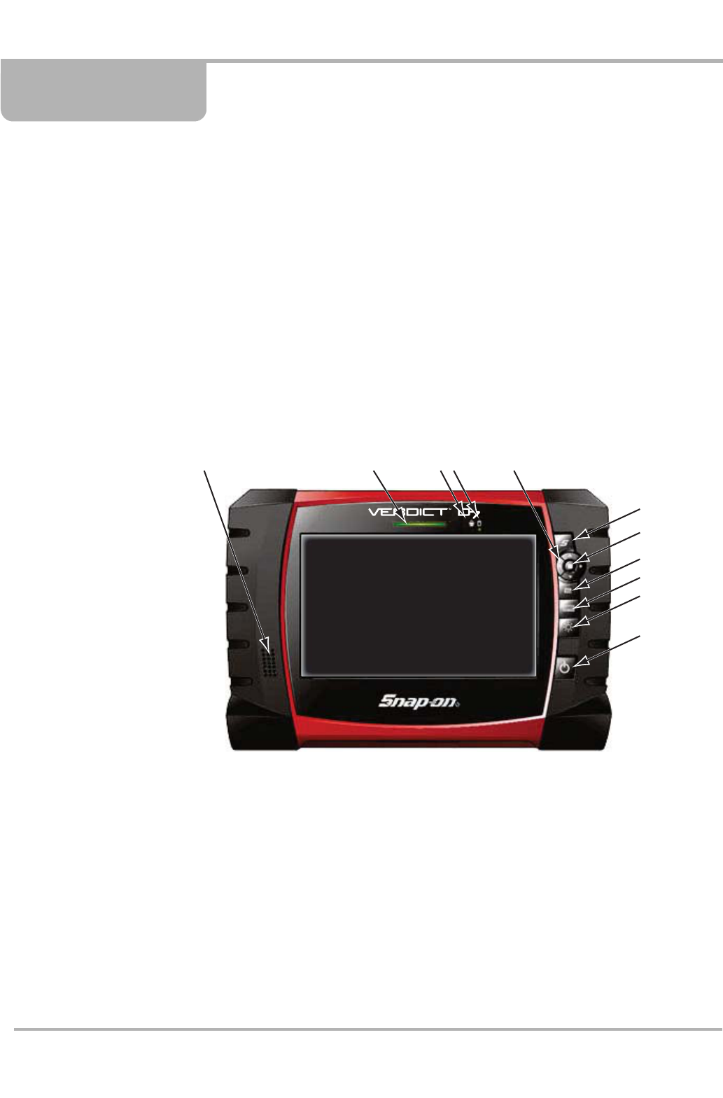
2.1 Functional Description
Figure 2-1 Model D7 front view
1— Audio Speaker
2— Power Indicator LED
3— Microphone
4— Hard Drive Activity LED
5— Directional Buttons; left (e), right (c), up (d), down (b)
6— S Button (special functions)
7— Enter(back) Button
8— Camera (shutter) Button
9— Virtual Keyboard Button
10—Brightness Button
11—Power Button
12345
6
7
8
9
10
11
DRAFT
4
Introduction Functional Description
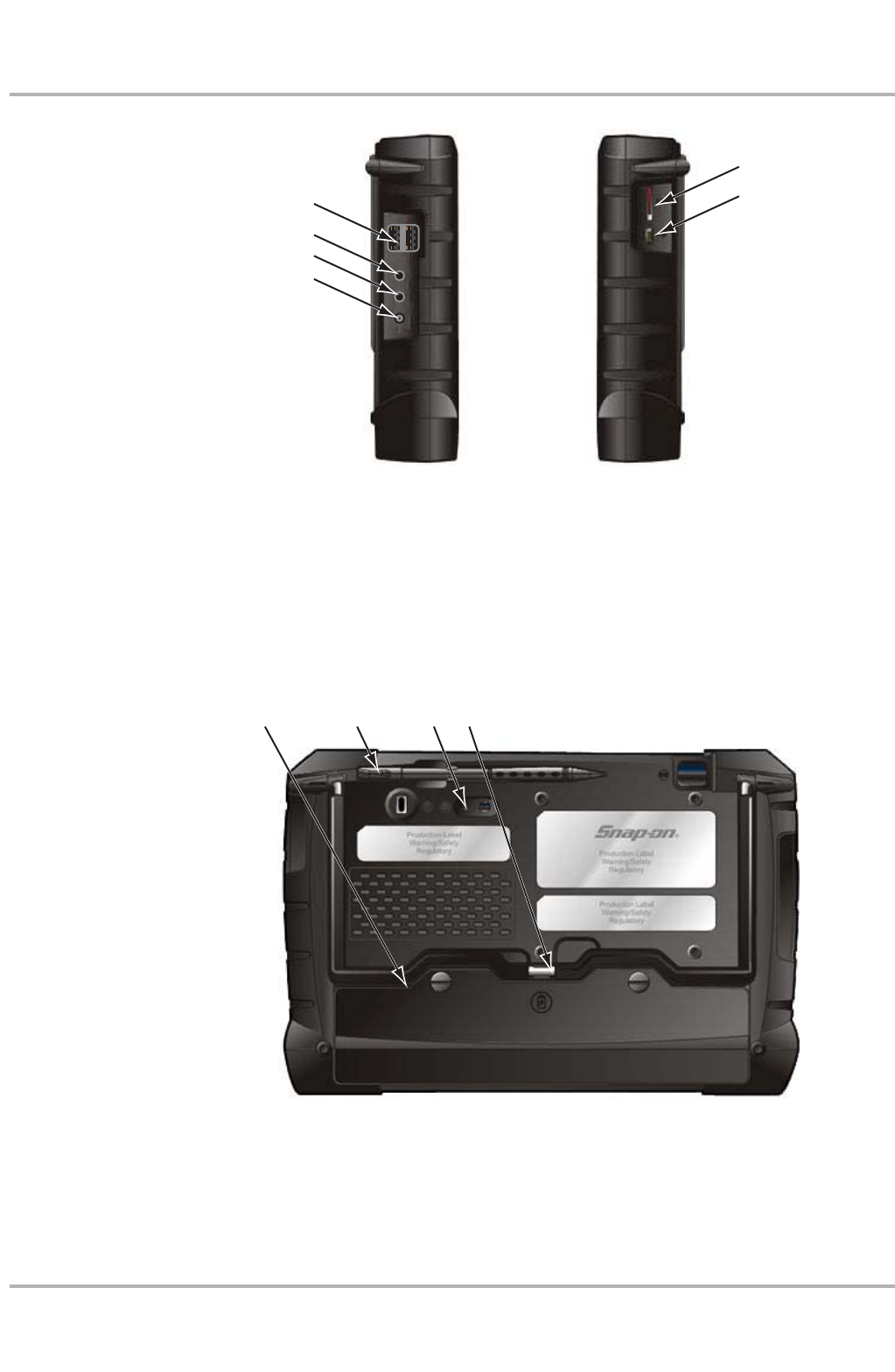
Figure 2-2 Model D7 side views
1— USB (universal serial bus) Ports (2)
2— Microphone Port
3— Audio (head phone) Port
4— DC Power Supply Input Port
5— SD (secure digital) Card Port
6— Mini USB Port
Figure 2-3 Model D7 back view
1— Battery Compartment Cover
2— Stylus
3— Camera Lens
4— Colapsable Stand (closed)
1
2
3
4
5
6
Left Side Right Side
12 43
DRAFT

5
Introduction Technical Specifications
2.2 Technical Specifications
Processor:
Intel Atom Z510
Operating System
Microsoft Windows XP Embedded SP2
Touch Screen
4-wire Resistive Touch Panel
Display:
7 inch diagonal, LCD TFT
1024 x 600 resolution
16 bit color
Battery:
Lithium Ion Smart Battery Pack
Approximately 3.5 hour run time
Approximately 4 hour charge time, unit not operating
Approximately 8 hour charge time, unit operating
Communications:
802.11 b/g/n Wireless
Bluetooth 2.0 Class 1
Dimensions:
Width:
9.9 inches
252 mm
Height:
6.8 inches
173 mm
Depth:
1.8 inches
46 mm
Weight (including battery):
2.7 lbs.
1.22 kg
Operating Temperature Range (ambient):
At 0 to 90% relative humidity (non-condensing)
32 to 113°F
0 to 45°C
DRAFT
6
Introduction Navigation, Controls, and Features
Storage Temperature (ambient):
At 0 to 70% relative humidity (non-condensing)
–4 to 140°F
–20 to 60°C
Environmental Conditions:
This product is intended for indoor use only
This product is rated for Pollution Degree 2 (normal conditions)
Power Supply:
Supply Rating; 19 VDC. 3.42A
2.3 Navigation, Controls, and Features
The external controls on the display device are simple because most operations are controlled
through the touch screen. Touch screen navigation is menu driven, which allows you to quickly
locate the test, procedure, or data that you need through a series of choices and questions.
Detailed descriptions of the menu structures are found in the sections for the various modules.
The following sections describe the external controls and features of the display device.
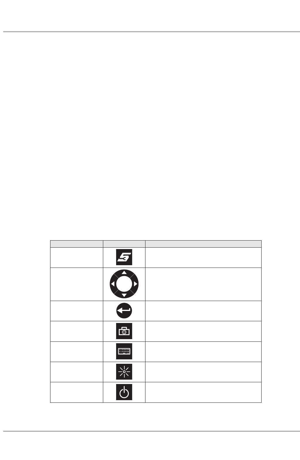
2.3.1 Control Buttons
Name and location of control buttons:
All other tool operations are controlled through the touch screen.
Name Button Description
S Button A function button that provides a shortcut for
performing routine tasks.
Directional Buttons Moves the cursor or highlight on the display
screen up, down, right, or left.
Enter Button Selects a highlighted item or returns the display
to the previous screen.
Camera Button Acts as a shutter for the built-in camera.
Keyboard Button Opens or closes the virtual keyboard.
Brightness Button Increases the screen backlighting in seven
ncremental steps.
Power Button Turns the unit on and off.
DRAFT

7
Introduction Power Sources
2.3.2 LEDs
There are two light-emitting diodes (LEDs) on the front face of the device:
•Power Indicator LED—this device uses three colors to show the batteryand power status as
follows:
–Green indicates a either a battery with a full, or nearly full, charge or DC power
–Orange indicates a battery that is charging. An orange LED that fades on and off at three
second intervals indicates the unit is in standby mode.
–Red indicates a low battery (15% of capacity or less).
•Hard Drive Activity LED—illuminates when the central processing unit (CPU) is reading or
writing to the hard disk drive (HDD).
2.3.3 The Stand
The built-in stand extends from the back of the unit to allow hands-free viewing. The stand clips
into the unit for storage and pivots out so the display is at a 35 degree angle when in use.
2.4 Power Sources
Your Display Device can receive power from any of the following sources:
•Internal Battery Pack
•AC/DC Power Supply
•Charging Station (Optional)
2.4.1 Internal Battery Pack
The display unit can be powered from the internal rechargeable battery. A fully charged standard
battery provides sufficient power for about 3.5 hours of continuous operation. An optional
high-capacity battery that provides 5.5 hours of operation is available. An LED on the front of the
unit indicates the battery state of charge.
2.4.2 AC/DC Power Supply
The unit can be powered from a wall socket using the AC/DC power supply and power cord. The
AC/DC power supply also powers the internal battery pack charging process.
2.4.3 Charging Station (Optional)
DRAFT

8
Introduction Power Sources
The unit can be powered and operated when installed on the optional charging, or docking station.
The docking station also powers the internal battery pack charging process and allows USB
connectivity for attaching peripherals. Contact your sale representative for additional details.
DRAFT
9
Chapter 3 Getting Started
Make sure the VERDICT D7 has a charged battery or is connected to an AC power supply (see
“Power Sources” on page 7). It is highly recommended to back up personal and saved data to a
USB mass storage device on a regular basis to prevent loss in the event of system corruption or
hard disk drive failure.
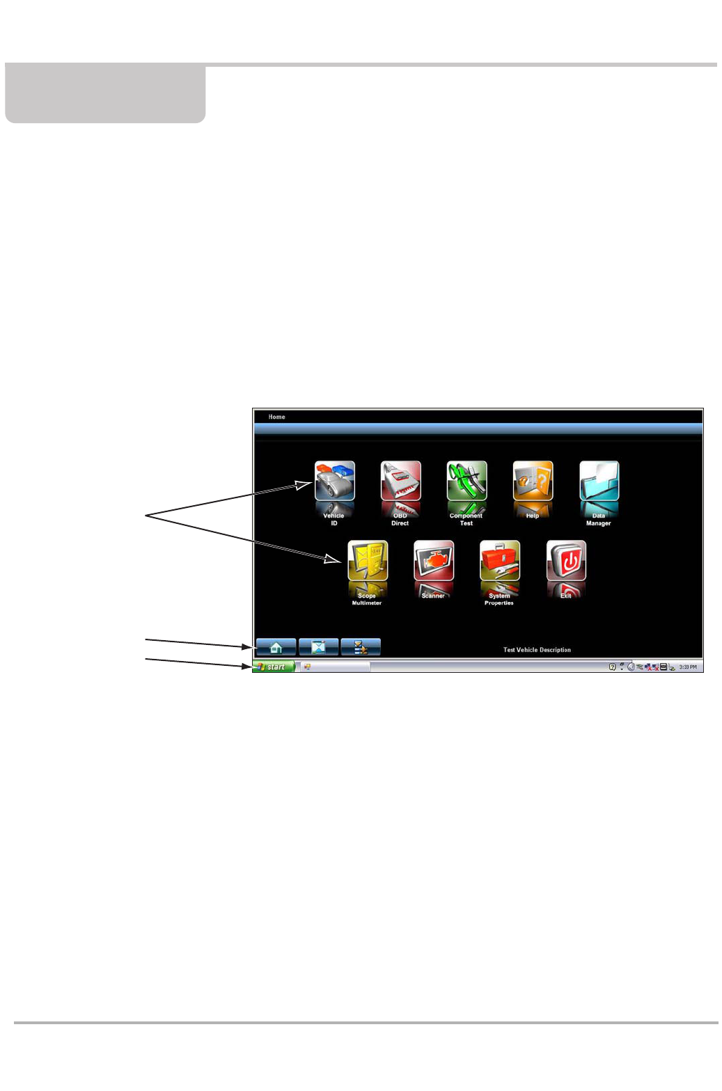
3.1 Powering Up
Press the Power button to switch the unit on. The system boots up, then opens the VERDICT
Home screen (Figure 3-1).
1— Module Buttons
2— VERDICT Toolbar
3— Windows Toolbar
Figure 3-1 Sample VERDICT Home screen
1
2
3
DRAFT
10
Getting Started Powering Up
3.1.1 Module Buttons
The Module buttons configure the VERDICT for the type of test to be performed. The table below
gives brief descriptions of the available Module buttons, which operations are available depends
upon the individual configuration of your VERDICT system.
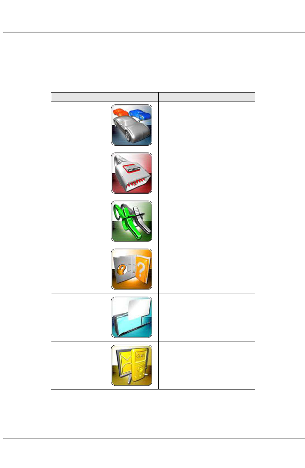
Table 3-1 Module buttons (sheet 1 of 2)
Name Button Description
Vehicle ID
Identifies the test vehicle and
organizes and manages work in
progress.
OBD Direct
Allows you to perform generic OBD-II
system tests without identifying the
specific vehicle.
Component Test Opens a diagnostic database of
specific tests for the identified vehicle.
Help Opens the on-line help for the system.
Data Manager Opens the organization system for
saved data files.
Scope Multimeter
Configures the unit to operate as a lab
scope, graphing multimeter, or digital
multimeter.
DRAFT
11
Getting Started Powering Up
Use the stylus or your finger tip to select from the Module buttons.
3.1.2 Verdict Toolbar
Operation of the toolbar buttons located on the lower-left corner of the screen are described in the
table below:
3.1.3 Windows Toolbar
This is the standard Windows XPe toolbar. Your VERUS unit is a fully functional personal
computer based on the Windows XPe operating system. Refer to Microsoft documentation for
additional information.
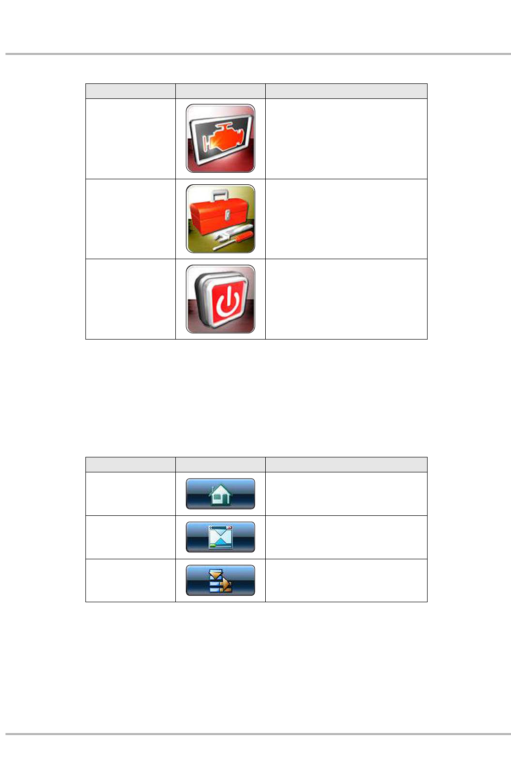
Scanner Configures the unit to operate as a
scan tool.
System Properties
Opens a window that contains details
about the configuration of your
VERDICT system.
Exit
Closes the VERDICT diagnostic
Platform software and returns to the
Windows desktop.
Table 3-1 Module buttons (sheet 2 of 2)
Name Button Description
Table 3-2 Module buttons
Name Button Description
Home Touching this button returns you to the
VERDICT Home screen from any test.
Windows Toolbar
Touching this button opens and closes
the standard Windows toolbars at the
top and bottom of the screen.
Menu
Touching this button opens a menu that
provides information on the screen
being viewed.
DRAFT

12
Getting Started Powering Down
3.2 Powering Down
All vehicle communication must be terminated before shutting down the VERDICT unit. Failure to
do so may lead to ECM problems on some vehicles. Exit the Scanner module before powering
down the VERDICT unit.
zTo power down the VERDICT unit:
1. Navigate to the VERDICT Home screen.
2. Select the Exit button.
3. From the Windows desktop, open the Windows Start menu.
4. Select Turn Off Computer.
5. Select Turn Off in the dialog box.
The open programs close and the power switches off.
3.2.1 Emergency Shutdown
In case of emergency, press and hold the Power button to force a shutdown.
DRAFT
13
Chapter 4 Operations
This section explains tests and operations that pertan to the display device only, or apply to all of
the available modules. Included here are discussions of:
•Vehicle ID
•Help
•Data Manager
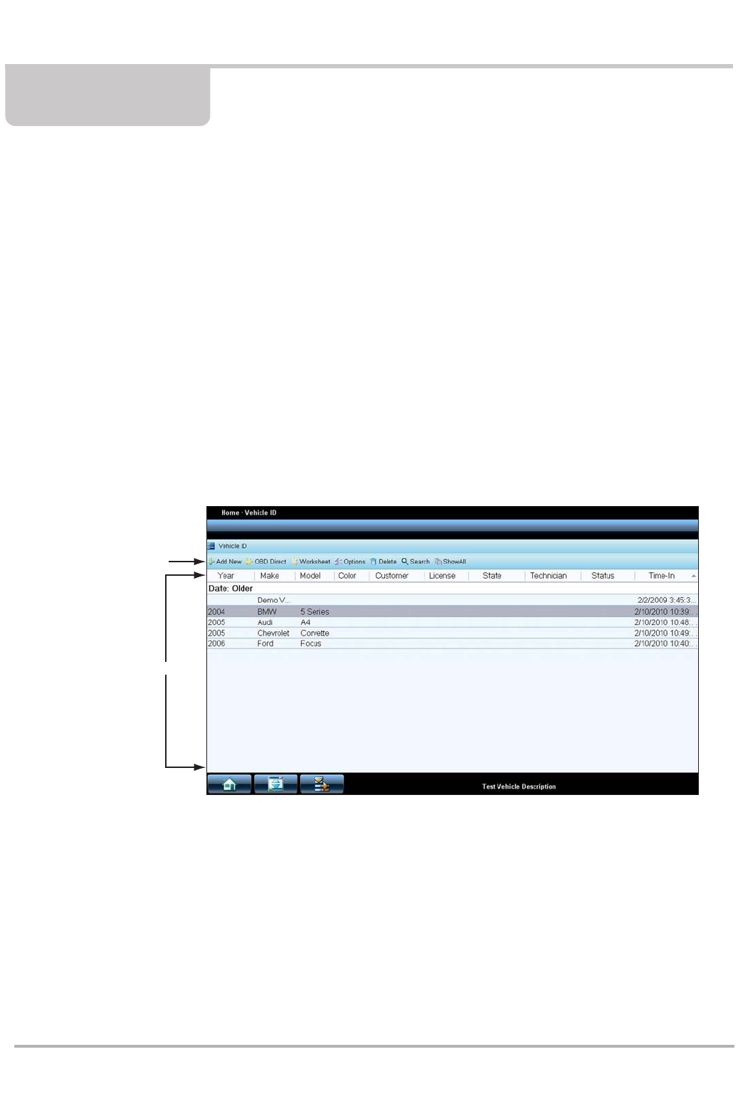
4.1 Vehicle ID
The Vehicle ID refers to any work in progress, such as a repair order, estimate or invoice, that has
customer, vehicle, and repair information for a vehicle in your shop. The Vehicle ID is the starting
point for using the VERDICT system. The Scanner and Component Test software get vehicle
information from the Vehicle ID, and can only start after a Vehicle ID is opened.
There are two main parts to the Vehicle ID screen:
1— Vehicle ID Toolbar—lets you manage the vehicle data
2— Main Body—lists all open Vehicle IDs
Figure 4-1 Sample Vehicle ID screen
1
2
DRAFT
14
Operations Vehicle ID
4.1.1 Vehicle ID Toolbar
The table below gives brief descriptions of the control buttons on the toolbar:
Add New
Use this button to generate a new service record.
zTo create a new Vehicle ID:
1. Select Add New from the toolbar.
The add Vehicle ID dialog box and the virtual keyboard open (Figure 4-2).
Figure 4-2 Sample add Vehicle ID dialog box
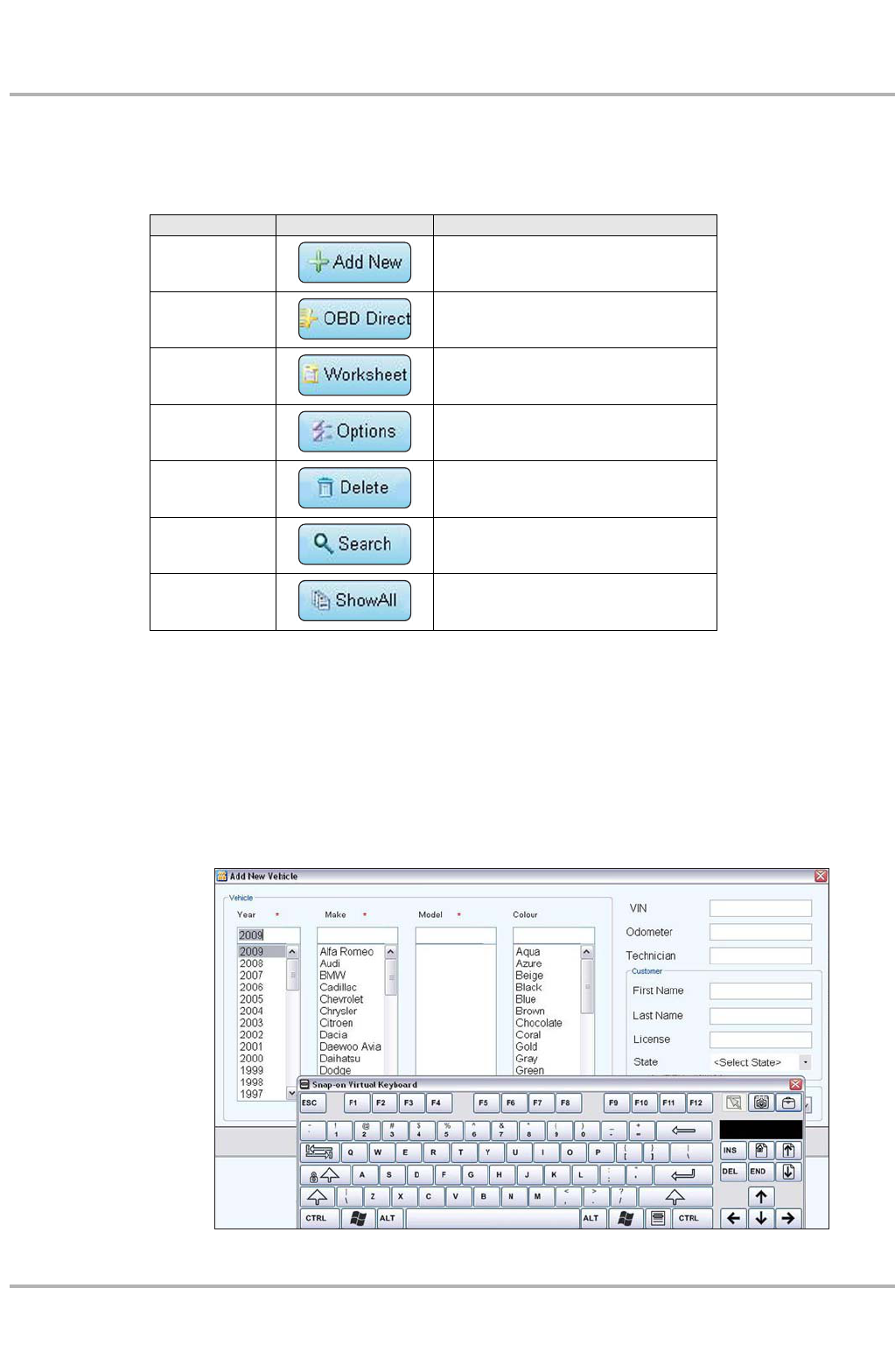
Table 4-1 Toolbar buttons
Name Button Description
Add New Use to create a new Vehicle ID
OBD Direct Use to quickly access generic OBD-II
data without a Vehicle ID
Worksheet Use to modify and add notes to a
Vehicle ID
Options Use to configure which fields display on
the main screen
Delete Removes a Vehicle ID from the list
Search Use to locate a specific Vehicle ID
Show All Available only after a search, use to
return to a complete Vehicle ID list
DRAFT

15
Operations Vehicle ID
2. Enter the year, make, and model of the test vehicle using either the dropdown menus or the
virtual keyboard.
NOTE:
iYear, make, and model are required fields, all other information on the dialog box is optional.
3. Fill in the other information as desired using the menus and keyboard.
4. Select OK to close the dialog box and return to the main Vehicle ID screen.
The new item now appears on the list and is highlighted.
OBD Direct
This is a shortcut that allows you to select generic Scanner tests from the Module Toolbar without
completing a Vehicle ID. This selection is designed for service writers and other personnel that
need to quickly access vehicle systems to determine what repairs are needed before a formal
work order or estimate is created.
Worksheet
Use this selection to edit, add notes, and print an existing Vehicle ID.
zTo modify an existing Vehicle ID:
1. Highlight the item to be modified, then select Worksheet.
The worksheet opens along with the virtual keyboard, and new buttons are available on the
toolbar.
2. Use the keyboard to enter information in the notes field, or to add an odometer reading.
3. Select Edit from the toolbar to make any other changes.
The Edit Vehicle ID dialog box opens. Use the menus and keyboard to make changes.
4. Select OK to return to the worksheet.
5. Select Save from the toolbar to save the changes you made.
6. Select Print from the toolbar to print a copy of the worksheet.
7. Select Close from the toolbar to exit the worksheet.
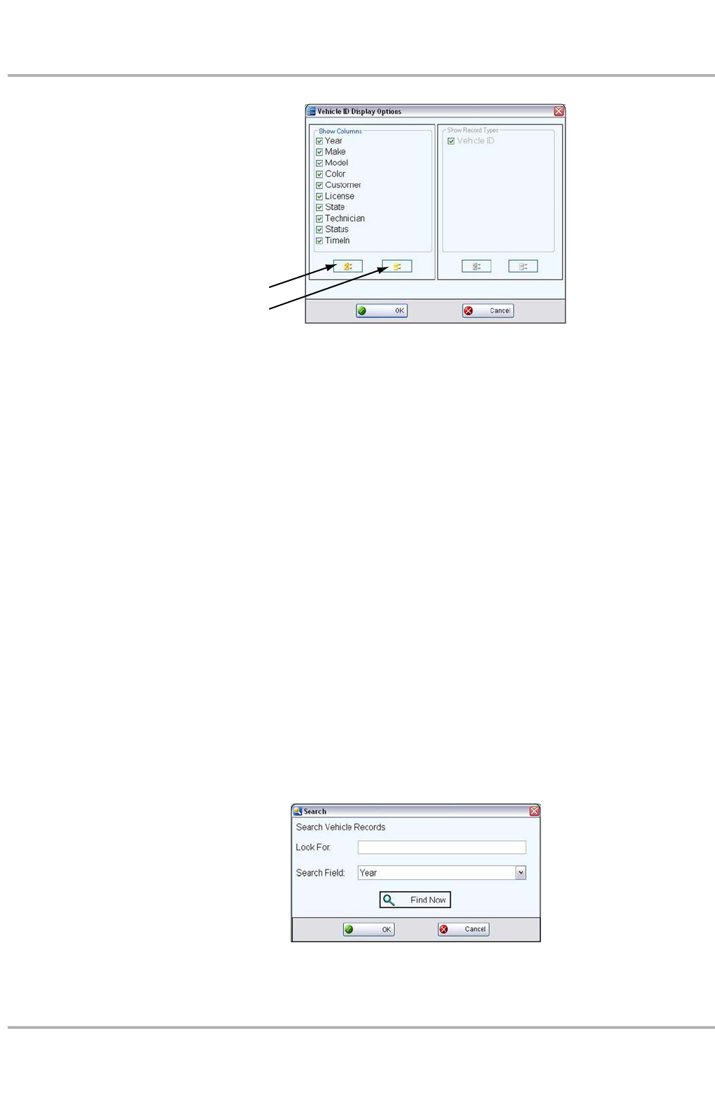
Options
Use Options to determine which categories of information display in the main body of the Vehicle
ID screen. Selecting the button opens the Display Options dialog box, shortcut buttons let you
select all or deselect all of the items in the list (Figure 4-3).
DRAFT
16
Operations Vehicle ID
Figure 4-3 Sample Display Options dialog box.
1— Select All Button
2— Deselect All Button
Individual selections must be made one at a time.
zTo change a display option:
1. Highlight the item to change with the stylus.
–items with a checked box display on the screen
–items with an unchecked box do not display on the screen
2. Select OK.
The dialog box closes and the screen updates.
Delete
Use the Delete button to remove unwanted items from the Vehicle ID list. Simply highlight the item
to remove, then select Delete.
Search
Selecting Search opens a dialog box that allows you to search Vehicle ID items by category
(Figure 4-4).
Figure 4-4 Sample Search dialog box
1
2
DRAFT

17
Operations Help
zTo search:
1. Use the virtual keyboard to enter search criteria.
2. Use the dropdown menu to select the field to search.
3. Select Find Now to start the search.
4. Select OK to close the Search window.
After a search, the Select All button becomes available on the toolbar.
5. Tap Select All to restore the complete Vehicle ID list.
4.1.2 Vehicle ID Main Body
The main body of the screen lists all of the available Vehicle ID items. By default, items are shown
in the order in which they are entered. However, you can resort them by any of the categories
shown as column headings. You can also resize the individual columns.
zTo sort Vehicle ID items:
1. Select a category heading.
The listed items resort according to the selected category. A triangle appears alongside the
name of the column that was used for the sort.
2. Select the triangle in the heading to reverse the sort order.
zTo resize a Vehicle ID column:
1. Touch the line separating two columns with the stylus.
A line with arrowheads appears to show the column is ready for resizing.
2. Drag the stylus to increase or decrease the column width.
4.2 Help
Selecting Help from the Home screen opens this manual. Two buttons at the top of the screen
allow you to select which format to view the files in:
•Help—displays in the web browser, use for screen viewing.
•PDF—displays in Acrobat Reader, use for printing
Figure 4-5 Help format selection buttons
Help is the default setting, so when the Help module is selected from the Home screen a hypertext
markup language (HTML) file opens in the browser.
DRAFT
18
Operations Help
A tool bar just below the options buttons is used to navigate the HTML file. Toolbar operations are
explained in the table below:
The three tabs below the toolbar control what displays in the left panel of the display:
•Contents—displays the table of contents for the manual, this is the defaut setting.
•Index—displays the index for the manual.
•Search—opens the search dialog box, which is the same as if selecting from the toolbar.
The scroll bars at the right side and bottom of each panel are used to move up and down and left
and right within the field. Touch and drag the divider bar between the two panels to resize the
panel widths.
When the PDF option is selected, use standard Acrobat navigation and operating procedures.
Refer to Adobe help for additional information.
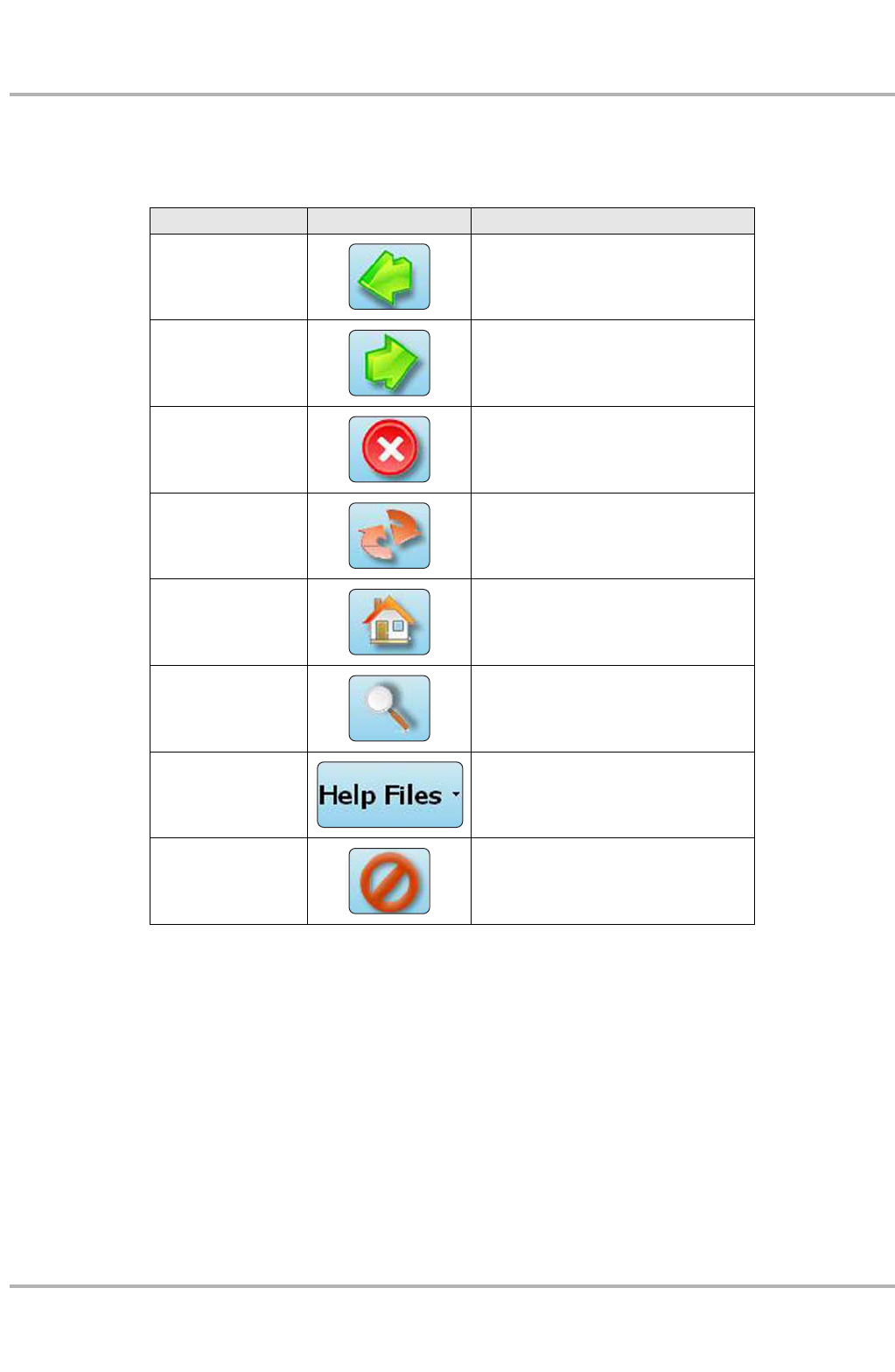
Table 4-2 Help toolbar buttons
Name Button Description
Back Returns to the previously viewed page
Next Advances to the next page
Stop Cancels the last command
Refresh Resamples and refreshes the current
page.
Home Returns to the first page of the
document
Search Opens a dialog box that allows you
enter and search for specific topics
Help Files
Opens a dropdown menu of all the help
files available for your VERDICT
components
Close Closes the help file
DRAFT
19
Operations Data Manager
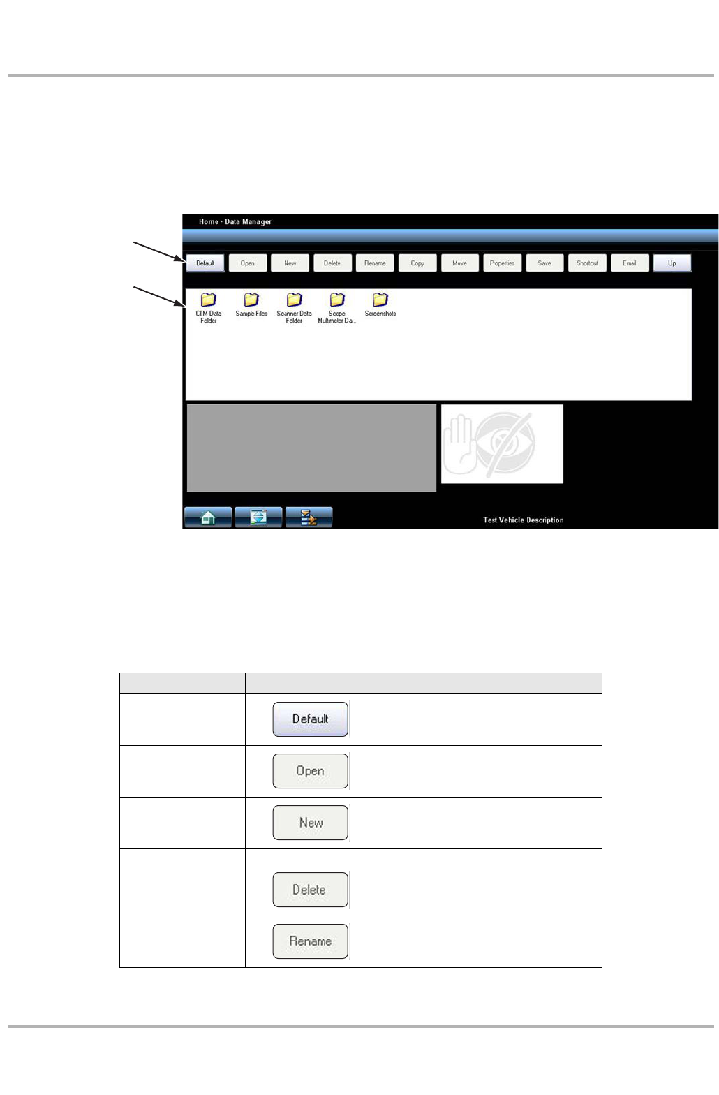
4.3 Data Manager
Select Data Manager on the Module toolbar to open the file system. Use the toolbar at the top of
the screen to navigate through the data. The folders panel below the toolbar displays the contents
of the Windows “My Documents” folder.
1— Data Manager Toolbar
2— Folders Panel
Figure 4-6 Sample Data Manager screen
The Data Manager module is used to store, sort, and review saved files. Most operations are
controlled through the toolbar. Toolbar functions are explained in the table below:
Table 4-3 Help toolbar buttons (sheet 1 of 2)
Name Button Description
Default Returns the folders view to the the
original (My Documents) view.
Open Opens the highlighted folder or file.
New Creates a new folder.
Delete
Deletes the highlighted file or folder. A
confirmation message that requires a
resopnse displays before the file is
permanently errased.
Rename
Opens a dialog box and the virtual
keyboard for renaming the selected file
or folder.
1
2
DRAFT
20
Operations Data Manager
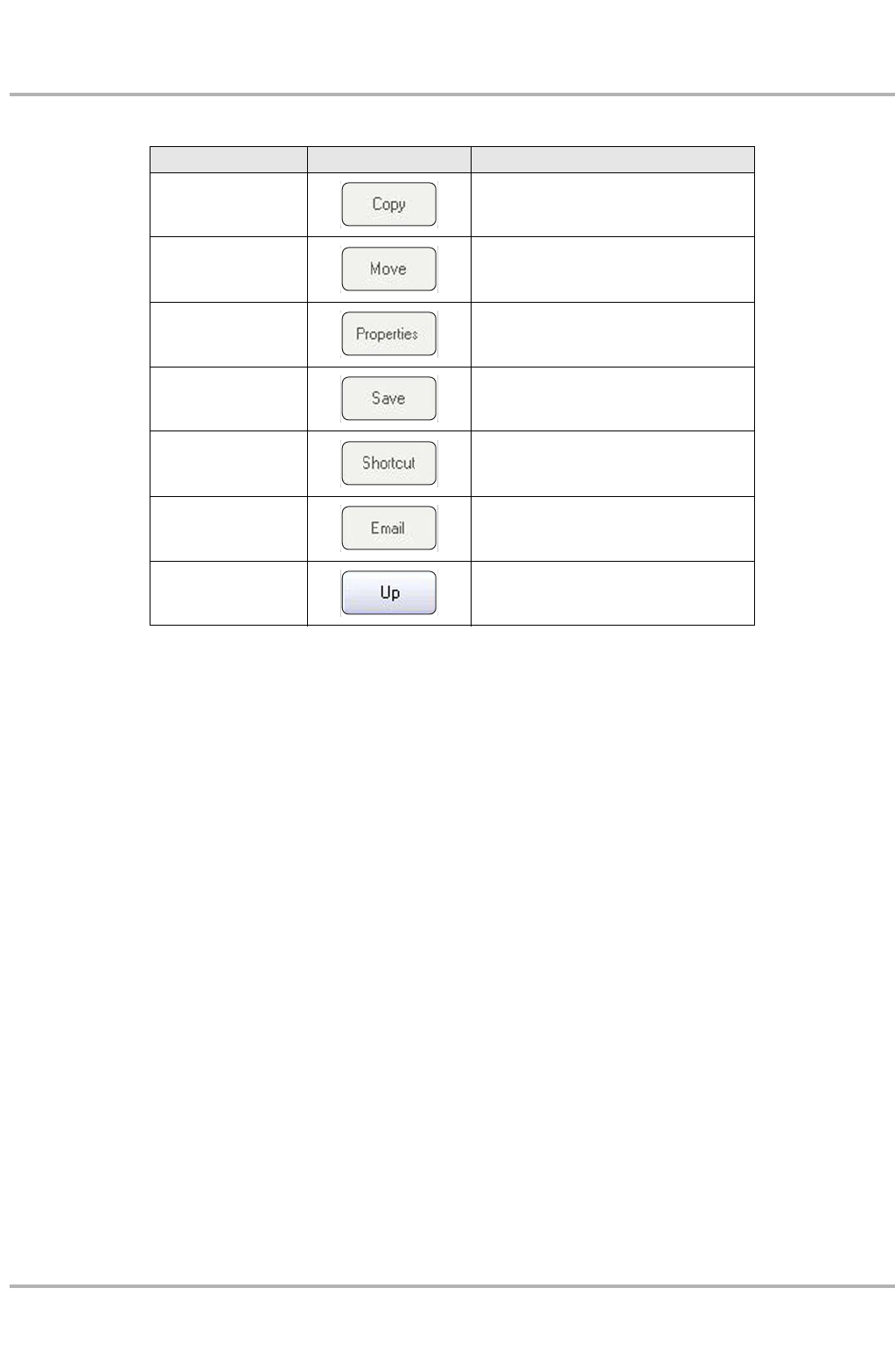
Copy Copies the selected file or folder.
Move Relocates the selected file or folder.
Properties Displays information about the selected
file or folder.
Save Saves the selected file.
Shortcut Creates a shortcut for the selected file
or folder.
Email
Attaches the selected file to a blank
e-mail form. An internet connection is
required.
Up Moves what is displayed in the folders
panel up one level.
Table 4-3 Help toolbar buttons (sheet 2 of 2)
Name Button Description
DRAFT

21
Chapter 5 Maintenance
This section covers how to care for your VERDICT Display Device.
5.1 Cleaning the Touch Screen
The touch screen can be cleaned with a soft cloth and alcohol or a mild window cleaner.
IMPORTANT:
Do not use any abrasive cleansers or automotive chemicals on the touch screen.
5.2 Cleaning and Inspecting the Unit
When using the VERDICT unit, make sure to do the following:
•Check the housing, wiring, and connectors for dirt and damage before and after each use.
•At the end of each working day, clean the housing, wiring, and connectors with a clean damp
cloth.
IMPORTANT:
Do not use any abrasive cleansers or automotive chemicals on the VERDICT Display Device.
5.3 Battery Service
Follow all safety guidelines when handling the battery pack.
!WARNING
Risk of electric shock.
• Prior to recycling the battery pack, protect exposed terminals with heavy insulating tape
to prevent shorting.
• Disconnect all test leads and turn diagnostic tools off before removing the battery pack.
• Do not attempt to disassemble the battery or remove any component projecting from or
protecting the battery terminals.
• Do not expose the unit or battery pack to rain, snow, or wet conditions.
• Do not short circuit the battery terminals.
Electric shock can cause injury.
DRAFT

22
Maintenance Battery Service
!WARNING
Risk of explosion.
• The Lithium battery is factory replaceable only, incorrect replacement or tampering with
the battery pack may cause an explosion.
Explosion can cause death or serious injury.
5.3.1 Battery Safety Guidelines
IMPORTANT:
The battery pack contains no user serviceable components. Tampering with the battery pack
terminals or housing will void the product warranty.
Keep the following in mind when using and handling the VERUS battery pack:
•Do not short circuit battery pack terminals.
•Do not immerse the VERDICT Display Device or battery pack in water, or allow water to enter
the unit or battery pack.
•Do not crush, disassemble, or tamper with the battery pack.
•Do not heat the battery pack to over 100°C (212°F), or dispose of it in a fire.
•Do not expose the battery pack to excessive physical shock or vibration.
•Keep the battery pack out of reach of children.
•Do not use a battery pack that appears to have suffered abuse or damage.
•Charge the battery pack in the appropriate charger only.
•Do not use a battery charger that has been modified or damaged.
•Use the battery pack for the specified product only.
•Store the battery pack in a cool, dry, well ventilated area.
NOTE:
iThe battery pack should be used within a short period of time (about 30 days) after charging to
prevent loss of capacity due to self-discharging.
If long-term storage of the battery pack is necessary, it should be stored in a in cool, dry, well
ventilated place with a 30 to 75 percent state of charge to prevent loss of characteristics.
To prolong the life of your battery, power off the unit or place it into hibernation mode when not in
use. The VERDICT unit has a built in charger that recharges the battery on demand whenever it
is connected to a power source.
5.3.2 Replacing the Battery Pack
If the battery pack no longer hold a charge, contact your sales representative to order a new one.
IMPORTANT:
Replace the battery pack with original Snap-on replacement parts only.
DRAFT
23
Maintenance Battery Service
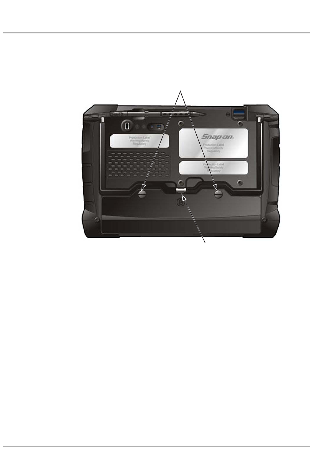
zTo replace the battery pack:
1. Remove the two captive screws the secure the battery pack to the back of the unit.
2. Insert a fingernail into the recess at the mid point of the top of the battery pack, then gently
raise the battery pack up to release the electrical connector.
1— Captive Screws
2— Lifting Recess
Figure 5-1 Battery pack replacement
3. Lift the battery pack clear of the unit.
4. Fit the three tabs on the bottom of the new battery pack into the slots, then rotate the assembly
into position.
5. Make sure the battery pack is fully seated.
6. Tighten the two captive screws.
5.3.3 Disposing of the Battery Pack
Always dispose of a lithium-ion battery pack according to local regulations, which vary for different
countries and regions. The battery pack, while non-hazardous waste, does contain recyclable
materials. If shipping is required, ship the battery pack to a recyling facility in accordance with
local, national, and international regulations. For additional information contact:
•North America—Rechargeable Battery Recycling Corporation (RBRC) at http://www.rbrc.org
or http://www.call2recycle.org, or call 1(800) 822-8837 (USA)
•United Kingdom—Electrical Waste Recycling Company at http://www.electricalwaste.com
Products bearing the WEEE logo (Figure 5-2) are subject to European Union regulations.
1
2
DRAFT

24
Maintenance Battery Service
Figure 5-2 sample WEEE logo
NOTE:
iAlways dispose of materials according to local regulations.
Contact your sales representative for details.
DRAFT

25
Index
A
AC/DC power supply 7
B
battery pack 7
disposing of 23
handling 22
replacing 22
specifications 5
C
charging station 8
cleaning the unit 21
D
Data Manager 19
dimensions, unit 5
display, specifications 5
E
Emergengy shutdown 12
H
help 17–18
M
maintenance
battery pack 21
manual conventions
description 1
notes 2
Modules 10
O
operating temperature 5
P
Power off 12
Power on 9
power sources 7–8
AC/DC power supply 7
S
Safety iii–iv
safety
information iii
message conventions iii
safety messages iii–iv
stand, the 7
storage temperature 6
T
temperature
operating 5
storage 6
V
vehicle identification 13–17
W
weight, unit 5
DRAFT