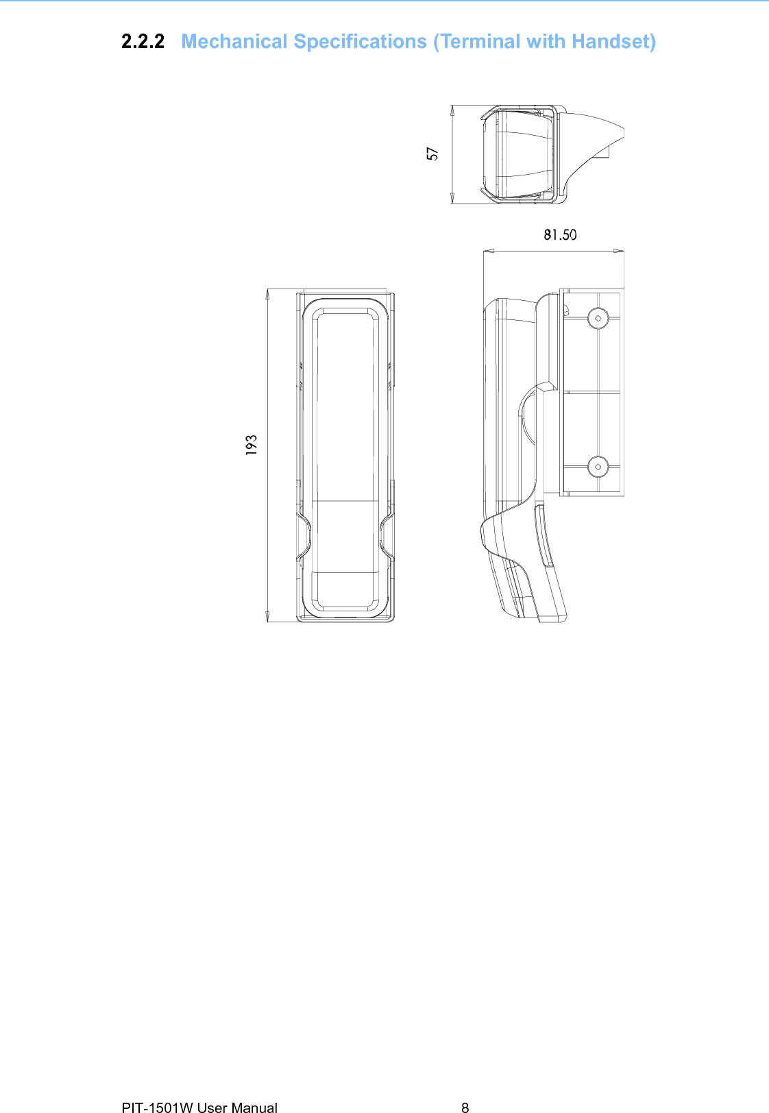
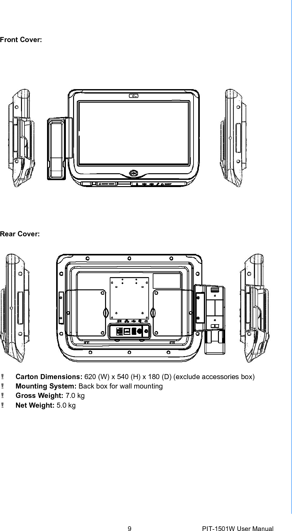
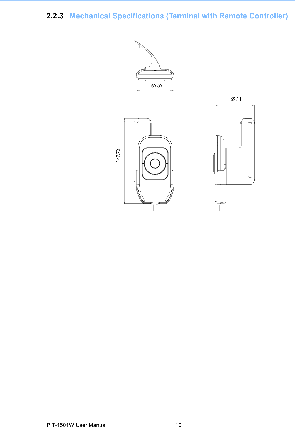
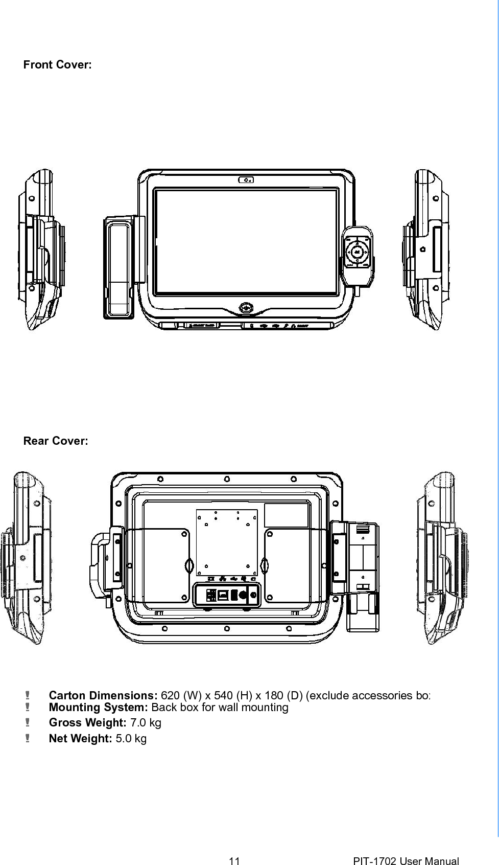
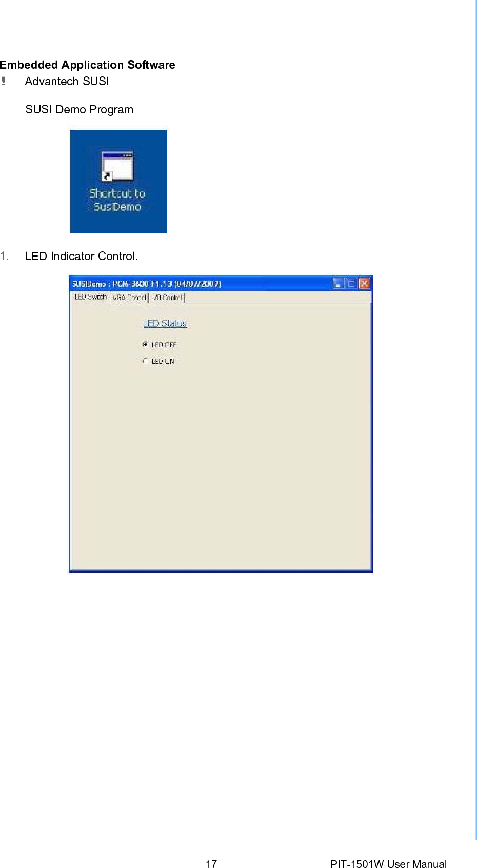
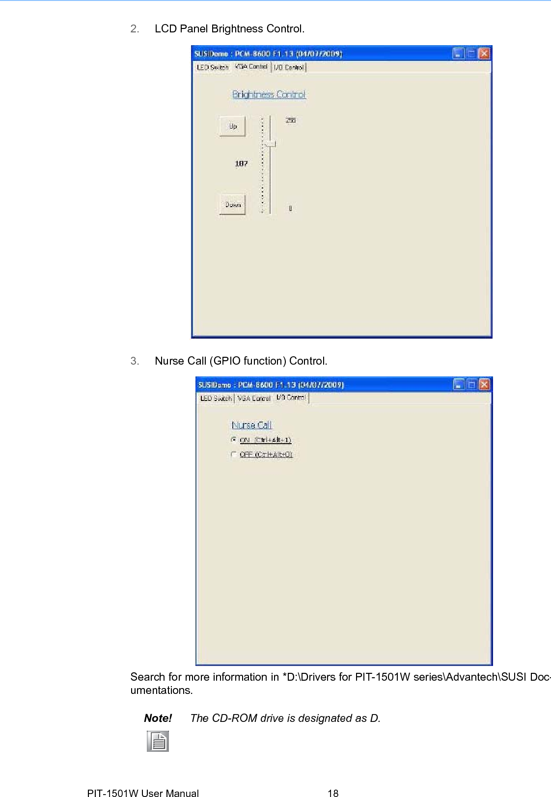
Advantech Co PIT-1501 Patient Infotainment Terminal/Computer User Manual PIT 1501W User Manual Ed1

Advantech Co Ltd Patient Infotainment Terminal/Computer PIT 1501W User Manual Ed1

Contents

User manual

User ManualPIT-1501WPatient Infotainment Terminal/Computer
Copyright  The documentation and the software included with this product are copyrighted 2009by Advantech Co., Ltd. All rights are reserved. Advantech Co., Ltd. reserves the rightto make improvements in the products described in this manual at any time without notice. No part of this manual may be reproduced, copied, translated or transmittedin any form or by any means without the prior written permission of Advantech Co.,Ltd. Information provided in this manual is intended to be accurate and reliable. How-ever, Advantech Co., Ltd. assumes no responsibility for its use, nor for any infringe-ments of the rights of third parties, which may result from its use. Acknowledgements Intel and Pentium are trademarks of Intel Corporation. Microsoft Windows and MS-DOS are registered trademarks of Microsoft Corp. All other product names or trademarks are properties of their respective owners.Declaration of ConformityFCC Class B Note: This equipment has been tested and found to comply with the limits foraClassB digital device, pursuant to part 15 of the FCC Rules. These limits are designed toprovide  reasonable  protection  against  harmful  interference  in  a  residentialinstalla- tion. This equipment generates, uses and can radiate radio frequency energyand, if not installed and used in accordance with the instructions, may cause harmfulinter- ference  to  radio  communications.  However,  there  is  no  guarantee  thatinterference will not occur in a particular installation. If this equipment does causeharmful interfer- ence to radio or television reception, which can be determined byturning the equip- ment off and on, the user is encouraged to try to correct theinterference by one or more of the following measures: ! Reorient or relocate the receiving antenna. ! Increase the separation between the equipment and receiver. ! Connect the equipment into an outlet on a circuit different from that to which the receiver is connected. ! Consult the dealer or an experienced radio/TV technician for help. Warning!  Any changes ormodifications madetothe equipment which are notexpressly approved by the relevant standards authority could void your authority to operate the equipment. Caution!  Danger of explosion ifbatteryis incorrectlyreplaced. Replace onlywiththe same or equivalent type recommended by the manufacturer. Dis- pose of used batteries according to the manufacturerís instructions. Part No. 2008170200 Edition 1 Printed in Taiwan April 2009 PIT-1501W User Manual ii
Technical Support andAssistance 1. Visit the Advantech web site at www.advantech.com/support where you can find thlatest information about the product. 2. Contact your distributor, sales representative, or Advantech's customer servicecenter for technical support if you need additional assistance. Please have thefollowing information ready before you call: ñ   Product name and serial number ñ   Description of your peripheral attachments ñ   Description of your software (operating system, version, application software,etc) ñ   A complete description of the problem ñ   The exact wording of any error messages  Warning!   1. Input voltage is rated 19 VDC, 2.63A (DCMode).2. Packing: Please carry the unit with both hands; handle with care. 3.  Maintenance: to properly maintain and clean the surfaces, use only approved products oclean with a dry applicator.  iii PIT-1501W User Manual
Safety Instructions 1. Read these safety instructions carefully. 2. Keep this User Manual for later reference. 3. Disconnect this equipment from any AC outlet before cleaning. Use a damp cloth. Do not use liquid or spray detergents for cleaning. 4. For plug-in equipment, the power outlet socket must be located near the equip- ment and must be easily accessible. 5. Keep this equipment away from humidity. 6. Put this equipment on a reliable surface during installation. Dropping it or lettingit fall may cause damage. 7. The openings on the enclosure are for air convection. Protect the equipment from overheating. DO NOT COVER THE OPENINGS. 8. Make sure the voltage of the power source is correct before connecting the equipment to the power outlet. 9. Position the power cord so that people cannot step on it. Do not place anything over the power cord. 10.   All cautions and warnings on the equipment should be noted. 11. If the equipment is not used for a long time, disconnect it from the power sourceto avoid damage by transient overvoltage. 12.   Never pour any liquid into an opening. This may cause fire or electrical shock.13.   Never open the equipment. For safety reasons, the equipment should be opened only by qualified service personnel. 14.   If one of the following situations arises, get the equipment checked by service personnel: a.  The power cord or plug is damaged. b.  Liquid has penetrated the equipment. c.  The equipment has been exposed to moisture. d.  The equipment does not work well, or you cannot get it to work according to the user's manual. e.  The equipment has been dropped and damaged. f.   The equipment has obvious signs of breakage. 15.   DO NOT LEAVE THIS EQUIPMENT IN AN ENVIRONMENT WHERE THE STORAGE TEMPERATURE MAY GO BELOW -20° C (-4° F) OR ABOVE 60° C(140° F). THIS COULD DAMAGE THE EQUIPMENT. THE EQUIPMENT SHOULD BE IN A CONTROLLED ENVIRONMENT. 16.   If your computer clock loses a significant amount of time or the BIOS configura-tion resets to default, the batteryhas no power.Caution!  1. Do not replacepoweradaptoryourself. Please contact a qualifiedtechnician or your retail. 2. The computer is provided with a battery-powered real-time clock circuit. There is a danger of explosion if battery is incorrectly replaced. Replace only with same or equivalent type recom- mended by the manufacture. Discard used batteries according to the manufacturerís instructions PIT-1501W User Manual iv
17.   CLASSIFICATION: ñ   Supplied by Class I adapter ñ   No applied parts ñ   Continuous operation ñ   No AP or APG category 18.   Follow national requirements to dispose of unit. 19.   Maintenance: To properly maintain and clean the surfaces, use only approvedproducts or clean with a dry cloth. 20.   Contact information: No.1, Alley 20, Lane 26, Rueiguang Road Neihu District, Ta i p e i , Ta i w a n 114, R.O.C TEL: (02) 2792-7818 21. 22.   This equipment is not to be used as alife support system.23.   Accessory equipment connected to the analog and digital interfaces must be incompliance with the respective nationally harmonized IEC standards (i.e. IEC 60950 for data processing equipment, IEC 60065 for video equipment, IEC 61010-1 for laboratory equipment, and IEC 60601-1 for medical equipment.) Furthermore all configurations must comply with the system standard IEC 60601-1-1. Anyone who connects additional equipment to the signal input part or signal output part is configuring a medical system, and is therefore, responsi- bthat the system complies with the requirements of the system standard IEC 60601-1-1. The unit is for exclusive interconnection with IEC 60601-1 certified equipment in the patient environment and IEC 60XXX certified equipment out- side of the patient environment. If in doubt, consult the technical services department or your local representative. 24.   A user must not allow SIP/SOPs and the patient to come into contact with one another at the same time. 25.   The sound pressure level at the operator's position according to IEC 704-1:1982is no more than 70dB (A). DISCLAIMER:  This  set  of  instructions  is  given  according  to  IEC  704-1.  Advantech disclaims all responsibility for the accuracy of any statements contained Note! Attention, please thoroughlyconsultthe accompanyingdocumentation.vPIT-1501W User Manual
PIT-1501W User Manual vi
Contents Chapter 1 Introduction..........................................11.1 Overview ................................................................................................... 21.2 System Configuration................................................................................ 4Chapter 2 Hardware Description .........................52.1 General Specifications .............................................................................. 62.1.1 Standard PC Functions ................................................................. 62.1.2 Flat Panel Interface ....................................................................... 62.1.3 Module Features ........................................................................... 62.1.4 Power Environment....................................................................... 62.2 Mechanical Specifications ......................................................................... 72.2.1 Mechanical Specifications (Terminal) ........................................... 72.2.2 Mechanical Specifications (Terminal with Handset) ..................... 82.2.3 Mechanical Specifications (Terminal with Remote Controller).... 102.2.4 Mechanical Drawing for Button I/O ............................................. 122.2.5 Mechanical Drawing for Rear I/O ................................................ 122.3 External View .......................................................................................... 132.3.1 Front View ................................................................................... 132.3.2 Side View .................................................................................... 142.3.3 Rear View ................................................................................... 14Chapter 3 Software Description.........................153.1 Windows XP Embedded Software Specifications ................................... 16Chapter 4 Design Requirements........................194.1 Environmental Specifications .................................................................. 204.2 Reliability ................................................................................................. 20Chapter 5 Installation..........................................215.1 Installation for Terminal........................................................................... 225.2 Installation for Handset ........................................................................... 235.3 Installation for Remote Controller............................................................ 245.4 Installation for Arm .................................................................................. 25vii PIT-1501W User Manual
PIT-1501W User Manual viii
Chapter 1 1    Introduction  This Chapter briefly introduces the PIT-1501W product. ! Overview ! System Configuration
1.1 Overview  The PIT-1501W Patient Infotainment Terminal is Advantechís standard product witha built-in Windows XP Embedded OS. In addition to providing hospital bedside patientinformation,  remote  monitoring,  and  care  functions,  the  CPU  and  the  LAN-enabled architecture of the PIT-1501W terminal also serves as an integrated hospitalgateway device.  The  PIT-1501W  equipped  with  an  Intel  Atom 1.6GHzprocessor,  15.6W touch screen,  onboard  Ethernet,  and  audio,  plays  a  keyrole  as  a  hospital  bedside care and monitoring solution. It connects the servicecalls and LED light signals of a hospital room through the LAN to the hospitalPIT-1501W User Manual 2
3PIT-1501W User Manual   1. Light Indicators  2. WIFI    3. Built-in 1.3 Mega-pixel CMOS Camera (optional) 4. Phone handset (optional)    5. Wired Remote Controller (optional) 6. RFID reader    7. Touch Screen    8. Nurse call with hard wire 9. Bottom I/O Arrangement (Mic-in, Line out, USB port ,Smart Card Reader) 10. Vesa Mounting /heat sink (75/100 compatible)    11. Access Door for CF card   12. Access Door for Hard drive and TV tuner Module.    1  1 2  234 6 78  91011 1314  14125
1.2 System Configuration The  block  diagram  of  a  PIT-1501W  Patient  Infotainment  Terminal  based  onHospital bedside environment is shown in the following diagram: Silverthorne XL 437 FCBGA8 1.6GHZ / FBS=533MHzCRT Conn. Analog RGBFSB 533/400200pin DDR2-SO-DIMM X 1 LVDS Connector Chrontel CH7308B LVDS TFT 18 x2 bit Intel 945GME(Calistoga)  SDVO DDR2 533/667 MT/STO I/O PCM-093 USB x 3 LVDSTFT 24 x2 bit DMI USB Portx1 (180D) PCI BUS 3.3V 33MHZ IDSEL:AD27 (PIRQC/A#, GNT#1, REQ#1) WIFI module ICH7-MUSB 2.0     AzaliaSmart Card Reader & SIM Card  USB Camera  USB TOUCH ELO USB Reserve x 1S-ATA HDD SATAX1LPCpage 17-19Codec   ALC888 IDE     P-ATA HDD Master Audio AMP TO I/O PCM-093Line-Out x1 Line-In x1 Mic In x1 SIO 3114 BIOSRS-232For RFIDPIT-1501W User Manual 4
Chapter 2 2    Hardware Description This Chapter describes the hard- ware features of the PIT-1501W. ! Main Specifications ! General Specifications ! Mechanical Specifications ! External View
2.1 General Specifications2.1.1 Standard PC Functions ! CPU: Silverthorne XL 1.6GHz ! BIOS: Award 1024K x 8 (8 Mbit) Flash BIOS ! Chipset: Intel 945GME + ICH7M ! Front side bus: Supports 400/533 MHz ! Memory: DDR2 SODIMM 400/533 MHz up to 2 GB ! Audio: HD audio codec ALC888 + 2 x 2.2 W amplifier ! LAN: Marvell Yukon 88E8071 PCI-E Gigabit Ethernet controller, ! SDVO/LVDS: Chrontel CH7307C SDVO to LVDS 18/24-bit transmitter ! Universal serial bus (USB) port: Supports up to 8 USB ports, 5 port for internal I/O ,3 ports for external I/O ! Mini PCIE bus expansion slot: Accepts one mini PCIE bus Card ! Disk drive housing: Space for one 2.5" SATA HDD/CF Card ! LED indicator: left and right side(orange)2.1.2 Flat Panel Interface! Power button: With LED indicator ! Audio: Mic-in, Line-out ! USB: USB x 3 ! LAN: Gigabit LAN ! SPK+MIC: build-in 2 x 2 W SPK + EM147 MIC ! Button: GPIO Programmable function ! Smart card reader: ISO7816 for IC card standard, PC/SC 1.0 for Windows, smart card standard, Microsoft WHQL, EMV for Europay MasterCard Visa stan- dard and USB-IF CCID standard 2.1.3 Module Features Features Interface Description Wi-Fi Wireless Mini PCIE 802.11b&g&n RFID Kit Internal UART 13.56 MHz,ISO-15693/14443 Camera module Internal USB 1.3 M pixels CMOS camera LED module GPIO Programmable, orange light Handset module RJ12 Build-in SPK & MIC Remote controller RJ12 Micro controller, up to 9 keys 2.1.4 Power Environment! Power adaptor: AC/DC ñ   Input voltage: 100 Vac ~ 240 Vacñ   Output voltage: 19 V @ 3.79 A! Medical adaptor: AC/DC ñ   Input voltage: 100 Vac ~ 240 Vacñ   Output voltage: 19 V@2.63APIT-1501W User Manual 6
2.2 Mechanical Specifications2.2.1 Mechanical Specifications (Terminal)! System Dimensions: 418 (W) x 308.4 (H) x65 (D) mm Front Cover: Rear Cover: ! Carton Dimensions: 620 (W) x540 (H) x180 (D) (excludes accessories box)! Mounting System: Back box for wall mounting ! Gross Weight: 7.0 kg ! Net Weight: 5.0 kg 7PIT-1501W User Manual
2.2.2 Mechanical Specifications (Terminal with Handset)  PIT-1501W User Manual 8
Front Cover: Rear Cover: ! Carton Dimensions: 620 (W) x540 (H) x180 (D) (exclude accessories box) ! Mounting System: Back box for wall mounting ! Gross Weight: 7.0 kg ! Net Weight: 5.0 kg 9PIT-1501W User Manual
2.2.3 Mechanical Specifications (Terminal with Remote Controller) PIT-1501W User Manual 10
Front Cover: Rear Cover: ! Carton Dimensions: 620 (W) x540 (H) x180 (D) (exclude accessories box! Mounting System: Back box for wall mounting ! Gross Weight: 7.0 kg ! Net Weight: 5.0 kg 11 PIT-1702 User Manual
2.2.4 Mechanical Drawingfor Button I/O2.2.5 Mechanical Drawingfor Rear I/O*External Switch Controller: Controlport forLCD on/off switch on front panel.PIT-1501W User Manual 12 Smart Card MICUSB USBLine OutMic InLine OutHand-Set Conn  Remote controller Conn Reserved portExternal Switch Controller USBDC inLAN
2.3 External View 2.3.1 Front View Front View (Terminal) Front View (Terminal with Remote Controller)Front View (Terminal with Remote Controller&Handset)13 PIT-1501W User Manual
2.3.2 Side View 2.3.3 Rear View Rear View (Terminal) PIT-1501W User Manual 14
Chapter 3 3    Software Description  This Chapter describes the soft- ware features of the PIT-1501W. ! Windows XP Embedded Soft- ware Specifications
3.1 Windows XP Embedded Software Specifications Real-Time OS Kernel ! Windows XPE 7 Language Version Driver List ! Chipset Intel US15W Rev:  ! Graphics Intel GMA500 Rev:  ! Audio Realtek Audio ALC880 Rev: 5.10.0.5512! LAN Marvell Yukon Ethernet Controller Rev: 8.61.7.3 ! Camera D-Max UVC 1.3M Webcam Rev: 6.11.200.4 ! Smartcard reader   ALCOR micro USB smartcard reader Rev: 5.11.9520.7! Touch Elo TtouchSys. 2216 AccuTouch@USB  Rev: 4.4.0.0 ! WLAN Qcom WIFI module Rev:1.2.3.0 PIT-1501W User Manual 16
Embedded Application Software! Advantech SUSI SUSI Demo Program 1. LED Indicator Control. 17 PIT-1501W User Manual
2. LCD Panel Brightness Control.3. Nurse Call (GPIO function)Control.Search formore information in *D:\Drivers forPIT-1501W series\Advantech\SUSI Doc-umentations. Note! The CD-ROMdrive is designated as D.PIT-1501W User Manual 18
Chapter 4 4    Design Requirements This Chapter describes the designrequirements of the PIT-1501W. ! Environmental Specifications ! Reliability
4.1 Environmental Specifications Temperature & Humidity ! Operating Temperature: 0 ~ 40° C ! Storage Temperature: 0 ~ 60° C ! Relative Humidity: 0 ~ 95% RH (Non-condensed)Case / Panel Temperature! Less than 40° C @ 25° C ambient temperature (front bezel) Safety ! CE EMI ! FCC class B approvedVibration:! 10 ~ 18 Hz, 1.5 mm peak-to-peak displacement! 18 ~ 500 Hz, 1 G acceleration 4.2 Reliability  MTBF ! 20,000 hours Touchscreen ! 1 million touch actuation times on a single point with a 5/8" diameter silicon fin- gunder a 350 g load at 2 Hz ! Power Requirements ! DC Input Voltage: 19 V ! Power Consumption: less than 60 W PIT-1501W User Manual 20
Chapter 5 5    Installation  This Chapter describes the instal-lation of the PIT-1702. ! Installation for Terminal ! Installation for Handset ! Installation for Remote Control- ler ! Installation for Arm
5.1 Installation forTerminal Step 1. Fix Hook. Step 2. FixARM + Handset Bracket +Remote Control Bracket. PIT-1501W User Manual 22
5.2 Installation for Handset Step 1. Fix Hook. Step 2. Fix ARM + Handset Bracket +Handset.23 PIT-1501W User Manual
5.3 Installation for Remote Controller Step 1. Fix Hook. Step 2. FixARM + Handset Bracket +Remote Control Bracket. PIT-1501W User Manual 24
5.4 Installation for Arm Step 1. Fix Hook. Step 2. Fix ARM + Handset Bracket +Handset.25 PIT-1501W User Manual
www.advantech.comPlease verify specifications before quoting. This guide is intended for referencepurposes only. All product specifications are subject to change without notice. No  part  of  this  publication  may  be  reproduced  in  any  form  or  by  any  means, electronic, photocopying, recording or otherwise, without prior written permis- sion of the publisher. All brand and product names are trademarks or registered trademarks of theirrespective companies.

Navigation menu