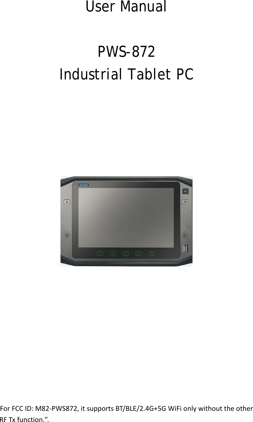
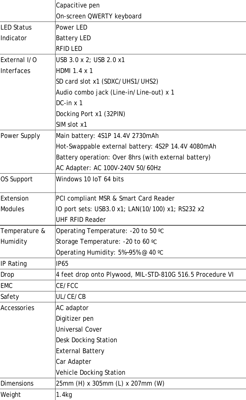
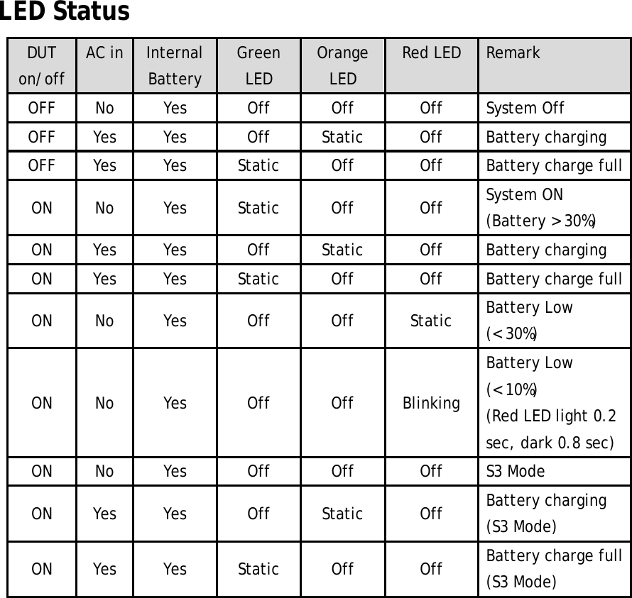
Advantech Co PWS872 Computer User Manual

Advantech Co Ltd Computer
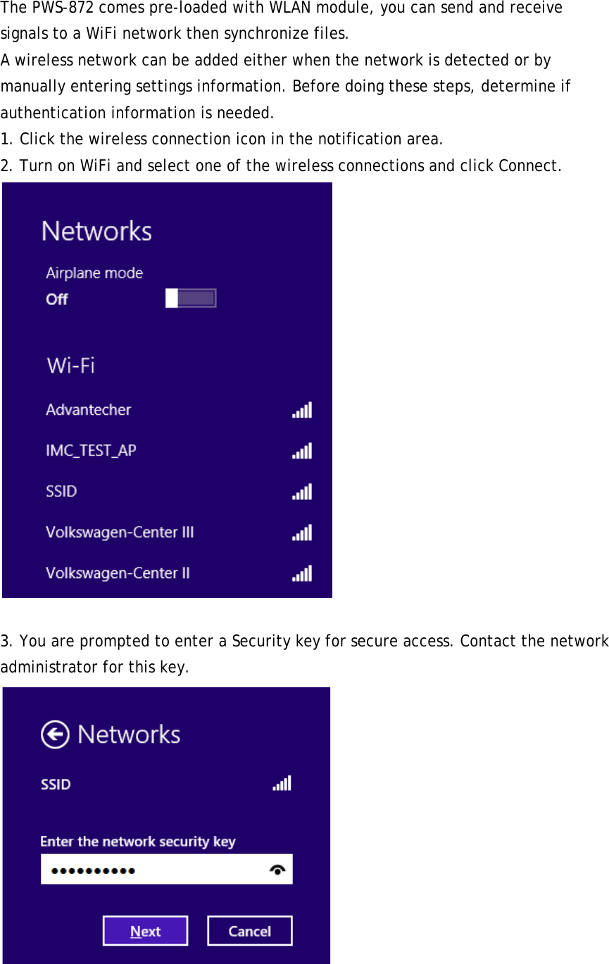
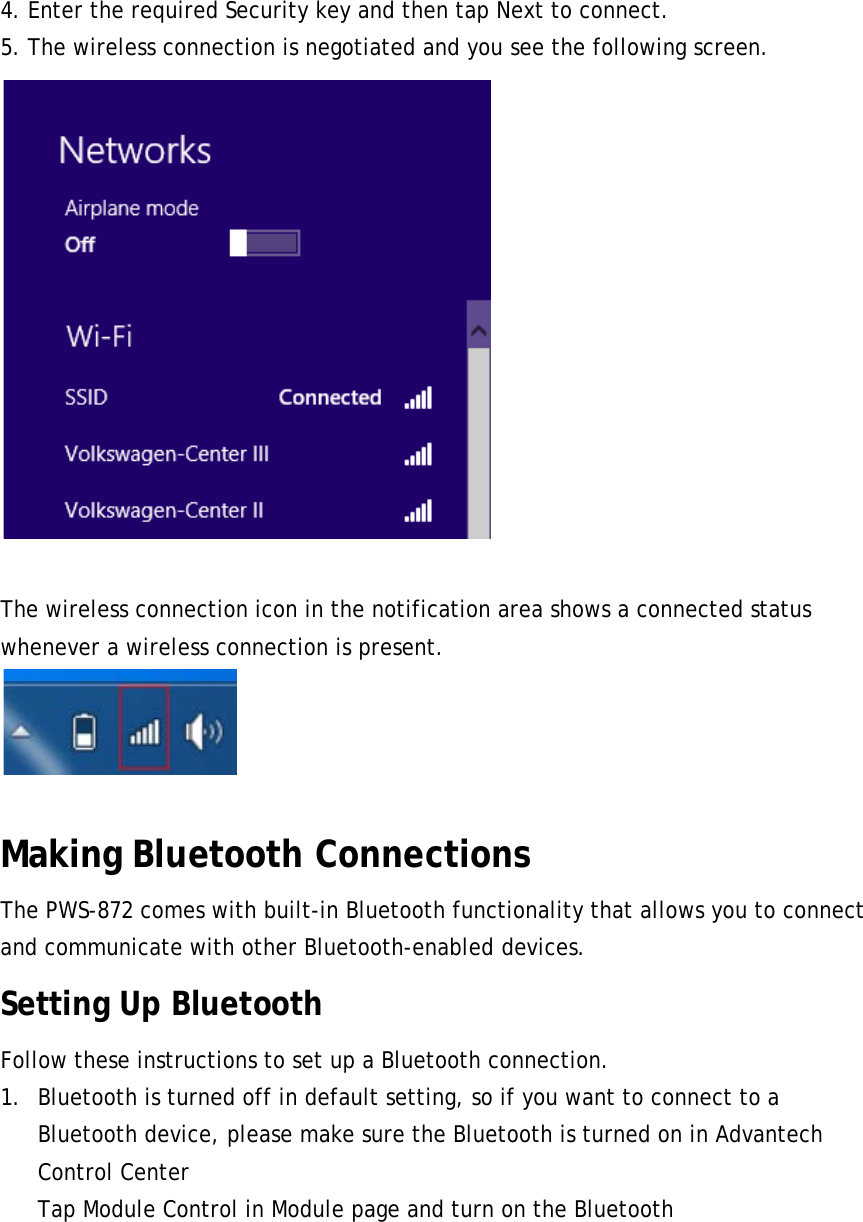
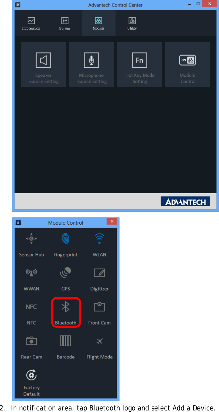
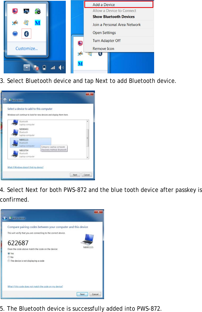
User Manual

User Manual  PWS-872 Industrial Tablet PC                  For FCC ID: M82-PWS872, it supports BT/BLE/2.4G+5G WiFi only without the other    RF Tx function.”.
Copyright The documentation and the software included with this product are copyrighted 2012 by Advantech Co., Ltd. All rights are reserved. Advantech Co., Ltd. reserves the right to make improvements in the products described in this manual at any time without notice. No part of this manual may be reproduced, copied, translated or transmitted in any form or by any means without the prior written permission of Advantech Co., Ltd. Information provided in this manual is intended to be accurate and reliable. However, Advantech Co., Ltd. assumes no responsibility for its use, nor for any infringements of the rights of third parties, which may result from its use. Acknowledgements All other product names or trademarks are properties of their respective owners.
Declaration of Conformity CE Conformity Statement Radio products with the CE alert marking comply with the R&TTE Directive (1999/5/ EC) issued by the Commission of the European Community. Compliance with this directive implies conformity to the following European Norms (in brackets are the equivalent international standards)   EN 60950-1 (IEC60950-1) - Product Safety Products that contain the radio transmitter are labeled with CE alert marking and may also carry the CE logo.  FCC Compliance Statement This device complies with part 15 of the FCC Rules. Operation is subject to the following two conditions: 1. This device may not cause harmful interference; 2. This device must accept any interference received, including interference that may cause undesired operation.  Any changes or modifications not expressly approved by the party responsible for compliance could void the user's authority to operate this equipment.  RF Exposure Information (SAR) This device meets the government’s requirements for exposure to radio waves. This device is designed and manufactured not to exceed the emission limits for exposure to radio frequency (RF) energy set by the Federal Communications Commission of the U.S. Government. The exposure standard employs a unit of measurement known as the Specific Absorption Rate, or SAR. The SAR limit set by the FCC is 1.6 W/kg. Tests for SAR are conducted using standard operating positions accepted by the FCC with the EUT transmitting at the specified power level in different channels. The FCC has granted an Equipment Authorization for this device with all reported SAR levels evaluated as in compliance with the FCC RF exposure guidelines. SAR information on this device is on file with the FCC and can be found under the Display Grant section of www.fcc.gov/oet/ea/fccid . To ensure that RF exposure levels remain at or below the tested levels, use a beltclip, holster, or similar accessory that have no metallic component in the assembly.
 This equipment has been tested and found to comply with the limits for a Class B digital device, pursuant to part 15 of the FCC Rules. These limits are designed to provide reasonable protection against harmful interference in a residential installation. This equipment generates, uses and can radiate radio frequency energy. If this equipment does cause harmful interference to radio or television reception, which can be determined by turning the equipment off and on, the user is encouraged to try and correct the interference by one or more of the following measures: However, there is no guarantee that interference will not occur in a particular installation. If this equipment does cause harmful interference to radio or television reception, which can be determined by turning the equipment off and on, the user is encouraged to try to correct the interference by one or more of the following measures:   Reorient or relocate the receiving antenna   Increase the separation between the equipment and receiver  Connect the equipment into an outlet on a circuit different from that to which the receiver is connected   Consult the dealer or an experienced computer technician for help Technical Support and Assistance 1. Visit the Advantech website at http://support.advantech.com where you can find the latest information about the product. 2. Contact your distributor, sales representative, or Advantech's customer service center for technical support if you need additional assistance. Please have the following information ready before you call: –  Product name and serial number –  Description of your peripheral attachments –  Description of your software (operating system, version, application software, etc.) –  A complete description of the problem –  The exact wording of any error messages Safety Instructions Use the following safety guidelines to help protect yourself and PWS-872  Do not attempt to service the PWS-872 yourself. Always follow installation instructions closely.
 Be sure that nothing rests on the AC adapter's power cable and that the cable is not located where it can be tripped over or stepped on.  Do not cover the AC adaptor with papers or other items that will reduce cooling; also, do not use the AC adapter while it is inside a carrying case.  Use only the AC adapter, power cord, and batteries that are approved for use with this PWS-872. Use of another type of battery or AC adapter may cause risk of fire or explosion.  If you use an extension cable with the AC adapter, ensure that the total ampere rating of the products plugged in to the extension cable does not exceed the ampere rating of the extension cable.  When you move the PWS-872 between environments with very different temperature and/ore humidity ranges, condensation may form on or within the PWS-872. To avoid damaging the PWS-872, allow sufficient time for the moisture to evaporate before using the PWS-872.  When you disconnect a cable, pull on its connector or on its strain relief loop, not on the cable itself. As you pull out the connector, keep it evenly aligned to avoid bending any connector pins. Also, before you connect a cable make sure both connectors are correctly oriented and aligned.  This Transmitter must not be co-located or operating in conjunction with any other antenna or transmitter.  This EUT is compliance with SAR for general population/uncontrolled exposure limits in ANSI/IEEE C95.1-1999 and had been tested in accordance with the measurement methods and procedures specified in OET Bulletin 65 Supplement C. This equipment should be installed and operated with minimum distance 1.3cm between the radiator & your body.  RF Exposure Information (SAR)  This device meets the government’s requirements for exposure to radio waves. This device is designed and manufactured not to exceed the emission limits for exposure to radio frequency (RF) energy set by the Federal Communications Commission of the U.S. Government.  The exposure standard employs a unit of measurement known as the Specific Absorption Rate, or SAR. The SAR limit set by the FCC is 1.6 W/kg. Tests for SAR are conducted using standard operating positions accepted by the FCC with the EUT transmitting at the specified power level in different channels. The FCC has granted an Equipment Authorization for this device with all reported SAR levels evaluated as in compliance with the FCC RF exposure guidelines. SAR information on this device is on file with the FCC and can be found under the
Display Grant section of www.fcc.gov/oet/ea/fccid .To ensure that RF exposure levels remain at or below the tested levels, use a beltclip, holster, or similar accessory that have no metallic component in the assembly.
Battery Safety RTC Battery Caution RISK OF EXPLOSION IF BATTERY IS REPLACED BY AN INCORRECT TYPE. DISPOSE OF USED BATTERIES ACCORDING TO THE INSTRUCTIONS.  Do not place the battery incorrectly as this may cause danger of explosion.  Dispose of used batteries according to the manufacturer's instructions.  Do not dispose of batteries in a fire. They may explode. Check with local authorities for disposal instructions.  Battery Pack Caution  The battery used in this device may present a risk of fire or chemical burn if mistreated. Do not disassemble, heat above 50°C, or incinerate. Replace internal battery with Li-ion 14.4V 2370mAh and Cell SANYO only. Use of another battery may present a risk of fire or explosion.  Dispose of used batteries according to local disposal regulations. Keep away from children. Do not disassemble and do not dispose of in a fire.  Battery Charge Notice It is important to consider the environment temperature whenever you are charging the Lithium-Ion battery pack. The process is more efficient at normal room temperature or slightly cooler. It is essential that you charge batteries within the stated range of 0°C to 40°C. Charging batteries outside of the specified range could damage the batteries and shorten their charging life cycle.  Storage and Safety Notice Although charge Lithium-Ion batteries may be left unused for several months, their capacity may be depleted due to the build up of internal resistance. If this happens they will require recharging prior to use. Lithium-Ion batteries may be stored at temperatures between -20°C to 60°C, however they may be depleted more rapidly at the high end of this range. It is recommended to store batteries within normal room temperature ranges.
Chapter 1 Industrial and Ready to Go
Congratulations on your purchase of the PWS-872 Industrial Tablet PC. This product combines industrial design with reliable performance and powerful functionality to best suit all your needs, in a wide range of working conditions. This user manual outlines all you need to know to set up and use your PWS-872. If you have any further questions or queries, contact our technical support team via our website: http://www.advantech.com.tw/  Symbols Used in this Manual  Denotes information that must be observed. Failure to do so may result in personal harm or damage to the product.   Denotes information that must be observed. Failure to do so may result in personal harm or damage to the product.  Product Features • Industrial design • High-performance Intel® Kaby Lake core i processor • Built-in WLAN/Bluetooth/GPS/WWAN/NFC functions • Durable, shock-resistant magnesium alloy housing • IP65 sealing & built to withstand a 4 ft drop • 10.1” Sunlight option / WXGA(1200x800) LCD • I/O ports for expansion • Long battery life  Package Contents Ensure all the following items are present when you receive your PWS-872. If any of these items are missing, contact your vendor immediately.  Screens used in this manual are for illustrative purposes only. Actual screens may vary depending on your product version.
• PWS-872 Tablet PC • AC power adaptor • Capacitive pen • Tether  Optional Accessories • Desk docking station • Vehicle docking station • External battery • External battery charger • Universal cover  • I/O Extension, MSR and Smart Card Reader Extension, UHF RFID Extension • Car adapter • Vesa mount •Screen Protection Film  Optional Modules • 1D / 2D barcode scanner • NFC Reader • LTE WWAN • GPS module • Fingerprint
Exploring the PWS-872 Front View   No. Component 1  2M Front Camera 2  Home Key (Programmable) 3  Function Key (Programmable) 4  Speakers 5  Fingerprint (Optional) 6  Capacity Hot Key(Programmable)     5 4 4 2  3 1 6
Rear View   No. Component 6  8M AF Camera with Flash Light 7  FAN 8  NFC RFID Reader (Optional) 9  Capacitive Pen 10 Latch (For External Battery & SIM Card Slot) 11 SIM Card Slot 12 Connector for External Battery     6 9 7 8 10 11 12
Side Views    No. Component 1  Kensington Lock 2  Power Button 3  Audio Combo Jack 4  HDMI Connector (1.4) 5  USB Connector (USB 3.0) 6  DC-in 7  Screw Holes for Extension Module 8  USB Connector (USB 3.0) 9  USB Connector (USB 2.0) 10 SD Card Slot (SDXC)       1 2 3 4 5 6 8 9 10 7 7
Top View    No. Component 1  D-Ring for Shoulder Belt  2  Vent of Fan 3  1D or 2D Barcode Scanner (Optional)  Bottom View   No. Component 1  Docking connector l    1 2 3 1 1
Chapter 2 Getting Started & Making Connections
Inserting a Memory Card   You can insert an SD card to store data, which needs to be later transferred to another machine, or to simply expand the storage capacity of the PWS-872.    1. Open the SD card compartment cover. 2. Insert the SD card with the metal contacts facing upwards, until it clicks into place. 3. Close the memory card compartment cover.  Removing a Memory Card 1. Open the SD card compartment cover. 2. Press the SD card inwards to eject it from the slot. 3. Remove the card and close the SD card compartment cover.  Installing a SIM  1. Make sure the system is turned off. Unlock the batter latch and remove the cover 2. Push and Open the SIM card cover. 3. Put the SIM card into the slot, with the metallic part facing down until it clicks into place. 4. Close the SIM card cover and push back the SIM card cover. 5. Lock the battery cover.
 Using the Tether 1. Insert one of the tether’s loop end through the hole of the capacitive pen.   2. Insert the other end through the first loop and pull it tight. 3. Insert the other loop end to either D-ring of PWS-872. Insert the capacitive pen through the loop and pull it tight  Connecting the Power Before you can use your PWS-872, you must fully charge the battery. Connect the power adapter as shown and leave to charge for: • A minimum of 2 hours when using the internal battery • A minimum of 5 hours when a second battery is installed   Connecting to a Monitor You can connect the PWS-872 to an external monitor for enhanced viewing. Connect one end of an HDMI cable to the HDMI port on the left side of the PWS-872. Connect the other end to the HDMI port on the monitor.   Connecting USB Devices
You can connect peripheral devices, such as a USB keyboard and mouse, as well as other wireless devices using the USB ports on the PWS-872. PWS-872 has one USB 3.0 port on the both sides and one USB 2.0 port on the left side.   Connecting Headphones/ Microphone You can connect a pair of headphones or microphone using the audio combo jack on the left side of the PWS-872.    PWS-872 uses audio combo jack therefore for microphone, PWS-872 only supports TRRS type. For headphones, both TRRS and TRS types can be supported.
Chapter 3 Turning on & Controlling the PWS-872
Turning On  1. Press and hold the power button to turn on the PWS-872.   24 Controlling the PWS-872 Using the Touch Screen The PWS-872 is equipped with touch screen technology, for ease of use when you are on the go. Simply tap the screen with your finger to select icons and run applications.  Using the Tap Function When you tap on the screen with the a pen or stylus, it emulates click functions of a regular mouse. • To emulate a left click single tap the screen once. • To emulate a right click tap and hold the screen. • To emulate a double click, tap the screen twice.  Using the Buttons There are two buttons on the front upper side of PWS-872. The button in the left side of panel is Home key. The other button in the right side of panel is for Barcode key (only suitable for the models equipped with barcode options)  There are 5 capacity hot key on the front lower side of PWS-872.
The buttons can be configured as shortcuts to access your favorite or frequently used programs. Please refer to chapter for more detail settings. Button Name Function  Home Press to return Home  Barcode Press to trigger barcode.  Capacity Hot Key
Using the On-Screen Keyboard Tap keyboard icon to bring up the on-screen keyboard.    Use your finger to tap and enter letters, numbers and symbols as you would with a regular keyboard.  Making WiFi Connection  WiFi access requires a separate purchase of a service contract with a wireless service provider. Contact a wireless service provider for more information.
 The PWS-872 comes pre-loaded with WLAN module, you can send and receive signals to a WiFi network then synchronize files. A wireless network can be added either when the network is detected or by manually entering settings information. Before doing these steps, determine if authentication information is needed. 1. Click the wireless connection icon in the notification area. 2. Turn on WiFi and select one of the wireless connections and click Connect.   3. You are prompted to enter a Security key for secure access. Contact the network administrator for this key.
4. Enter the required Security key and then tap Next to connect. 5. The wireless connection is negotiated and you see the following screen.   The wireless connection icon in the notification area shows a connected status whenever a wireless connection is present.   Making Bluetooth Connections The PWS-872 comes with built-in Bluetooth functionality that allows you to connect and communicate with other Bluetooth-enabled devices. Setting Up Bluetooth Follow these instructions to set up a Bluetooth connection. 1. Bluetooth is turned off in default setting, so if you want to connect to a Bluetooth device, please make sure the Bluetooth is turned on in Advantech Control Center Tap Module Control in Module page and turn on the Bluetooth
  2. In notification area, tap Bluetooth logo and select Add a Device.
     3. Select Bluetooth device and tap Next to add Bluetooth device.  4. Select Next for both PWS-872 and the blue tooth device after passkey is confirmed.  5. The Bluetooth device is successfully added into PWS-872.
 6. To view Bluetooth device added, tap Show Bluetooth Devices.     It is recommended that you use a passkey to prevent unauthorized access to your PWS-872.
Chapter 4 Using Advantech Control Center
Advantech Control Center for PWS-872 Advantech Control Center is a useful tool for user to get PWS-872 basic system information and control PWS-872 easily  System Information Tap “Information” of Advantech Control Center to get the basic information of the system which includes followings:  Batteries capacity information  CPU temperature  Fan speed  Version of CPU, EC, PCB, and BIOS  Product serial number  Advantech Control Center version
System Control Tap “System” of Advantech Control Center to configurate basic control setting.  Brightness: Tap Brightness in System page and the screen brightness control bar will show up. User can scroll the bar to adjust the screen brightness. Check “Auto Brightness” to enable auto brightness feature.
 Volume: Tap Volume in System page to configurate the speaker volume.  Microphone: Tap Microphone in System page to configurate microphone volume.
Resolution: Tap Resolution in System page to adjust screen resolution and orientation mode. Check “Allow the screen to auto-rotate” if user wants to enable screen auto rotation.    Text Size: Tap Text Size in System page to change text size.
Calibration Tap Calibration in System page to re-calibrate touch screen.  The accuracy of capacitive touch screen might vary according to different environments; therefore it is suggested to re-calibrate touch screen once user feel the touch screen is not as accurate as usual. Please use mouse instead of finger for re-calibration. Use mouse to click Start and wait for the process of calibration. DO NOT touch the screen during the calibration process.  Once the calibration is done, user can see below message.  Power Management: Tap Power Management in System page to choose or customize power plan.
Module Control Tap “Module” of Advantech Control Center to configurate module setting.  Speaker Source Setting: Tap Speaker Source Setting in Module page to choose preferred speaker source (when PWS-872 is docked).
Microphone Source Setting: Tap Microphone Source Setting in Module page to choose preferred microphone source (when PWS-872 is docked).  Hot Key Mode Setting: Tap Hot Key Mode Setting in Module page to configurate hot key function. There are three pre-set modes, users can choose either one or customize their own setting.  (i) Brightness Adjustment.   Users can tap Brightness Adjustment to configurate hot key to control panel brightness. The default setting is the right key (barcode key) to increase panel brightness and the left key (home key) to reduce panel brightness. Users can click “Switch Key Control” to switch the function of the two buttons.    Once the “Switch Key Control” is clicked, this switch setting will apply to all hot key modes Users can click “Auto Brightness” to enable auto brightness/light sensor function. Once “Auto Brightness” is enabled, users cannot adjust panel brightness manually.
 (ii) Windows Home & Barcode Trigger This is the default hot key setting. The right button is for barcode trigger and the left button is for Windows Home. Users can click Switch Key Control to switch functions of left and right buttons.    Once the “Switch Key Control” is clicked, this switch setting will apply to all hot key modes
Once the hot keys are set to Windows Home & Barcode Trigger mode, the barcode will be turned on automatically. Users can press barcode trigger hot key to scan any barcode and the barcode information can show in the notepad or word file. (iii) Personalize Hot Key Function Users can user this to configure hot keys to their desired functions.  (iv) Volume Adjustment By choosing this setting, the hot keys can be use to increase or reduce speaker volume.
  Module Control: Tap Module Control in Module page to control the on/off of each function. Users can easily tap the icons to power on or power off of each single function in this page. User can tap Factory Default to reset module on/off control to default settings (WLAN and fingerprint on; other modules off) or tap Flight mode to turn off all RF related modules (WLAN, WWAN, GPS, NFC and Bluetooth)
Utility Tap “Utility” of Advantech Control Center to access demo utilities    Before you try these utilities, make sure the module related to the utility is set as “ON” in the Module Control page  Light Sensor: Tap Light Sensor in Utility page and the demo light sensor utility will pop up and will show the current lux information. The lux information will vary according to the light of the environment (if the light sensor is on)
 Camera: Make sure the camera module is turned on in the Module Control page. Tap Camera in Utility page and the camera utility will pop up. Users can tap icon  to select either front camera or rear camera and do photo shooting  or video recording . If flash light is needed (available for rear camera), tap  to enable flash light.  Users can tap on   to do camera setting as below.
 Sensor Hub: Make sure the sensor hub is turned on in the Module Control page. Tap Sensor Hub in Utility page, the Sensor Diagnostics Tool will pop up. This tool will provide the raw data of each sensor.   WWAN AirCard: Make sure the SIM card is installed before using this function. Tap WWAN AirCard in Utility page, the Skylight utility will pop up and search for carrier.
 Tap “Connect” to connect to carrier.   Once connection is made, you can connect to internet
 GPS Info: Make sure GPS is turned on in the Module Control page. Tap GPS Info in Utility page, the GPS Information utility will pop up. Set COM Port to COM1 and Baud Rate to 9600 and then click Start GPS. You will get GPS information.    Fingerprint Demo: Make sure fingerprint is turned on in the Module Control page. Tap Fingerprint Demo in Utility page, the Fingerprint Demo utility will pop up.
 Tap Grab and follow the instruction to swipe the finger to get the fingerprint data. Users can save or load the fingerprint data.
NFC : Make sure NFC is turned on in the Module Control page. Tap NFC in Utility page, users will be directed to Stollmann’s website for NFC utility download    Fill in the information to register. After registration, users will get an email notification with download link provided. Use that link to download Stollmann NFC utility. After download of Stollmann NFC, run the utility. Click Configure and set the Controller to ETSIHCI (PN544), Bus to Serial, Port to COM3 and then click Save
 Click Start NFC and the utility will try to detect if the device is equipped with NFC solution. The detection result will be shown in the lower left corner of the utility.  Click Start RW, and put the card near the scan area (on the back side of PWS-872). You can see the scanned data. The scanning distance is around 3-4 cm.
 If users want to change data with another device with NFC function, users can try the P2P feature. Click SNEP server and then Start P2P  Put together both device and user can see the other device will be detected.
 Ignition Setting: This setting is only for vehicle docking application. If users enable this ignition feature, when PWS-872 is docked in the vehicle docking station then it will turn on or off automatically when vehicle ignition on/off. Users can configurate the countdown period (0.5 to 30 minutes) for PWS-872 turn off. Tap Ignition Setting in Utility page, choose enable or disable. If choose enable, select the countdown time period.   When PWS-872 is docked and vehicle is turned to ignition off, the PWS-872 will pop up a countdown warning message as below. User can tap OK to turn off PWS-872 or tap Cancel to keep PWS-872 on. If not action is taken, PWS-872 will automatically shut down after countdown period.
Chapter 5 Maintenance
Maintaining the Battery • Do not expose heat or attempt to disassemble the battery, and do not place the battery in water or in a fire. • Do not subject the battery to strong impact, such as a blow from a hammer, or stepping on or dropping it. • Do not puncture or disassemble the battery. • Do not attempt to open or service the battery. • Replace only with batteries designed specifically for this product. • Keep the battery out of reach of children. • Dispose of used batteries according to local regulations. Maintaining the LCD Display • Do not scratch the surface of the screen with any hard objects. • Do not spray liquid directly on the screen or allow excess liquid to drip down inside the device. • Do not place anything, such as food and drink, on the screen at any time to prevent damage to the screen. • Clean the LCD display only with a soft cloth dampened with denatured alcohol or a proprietary LCD screen cleaner. Cleaning the PWS-872 1. Turn off the PWS-872 and unplug the power cord. 2. Wipe the screen and exterior with a soft, damp cloth moistened only with water. Do not use liquid or aerosol cleaners on the screen, as these will discolor the finish and damage the screen. PWS-872 User Manual
Chapter 6 Appendix
Specifications Feature Specifications CPU & Chipset Intel® Celeron Processor 2.2 GHz 3965U  Intel® Core™ i3 Processor 2.4 GHz 7100U  Intel® Core™ i5 Processor 2.6 GHz 7300U with Turbo Boost to 3.5GHz  Intel® Core™ i7 vPro™ Processor 2.8 GHz 7600U with Turbo Boost to 3.9 GHz  Memory SO-DIMM DDR4 2133MHz up to 8GB Storage Support mSATA SATAIII SSD 64GB~512GB Display 10.1" HD (1280x800) Low reflection LED Backlight LCD (350 nits) Touch Panel Capacitive multi touch  Sunlight readable feature Display with Corning® Gorilla® Glass Gen3 Sensor Ambient light, Accelerometer (G-sensor), E-compass , Gyroscope Sensor - Screen Rotation: 0°, 90°, 270° Wireless Communication Default WIFI 802.11 a/b/g/n/ac Default Bluetooth V4.1 (Class2) + EDR Optional integrated LTE mobile broadband Optional dedicated GPS Camera Front Camera: 2M pixel CMOS Sensor; support Video Streaming Rear Camera: 8M pixel CMOS Sensor; with LED flash light and auto focus control Data Collection Optional Built-in 1D barcode scanner Optional Built-in 2D barcode scanner  Optional Built-in NFC RFID reader Security 1. Optional Fingerprint scanner 2. TPM 1.2  3. Kensington cable lock slot Audio Output  Integrated speakers Integrated microphone Input Capacitive multi-touch Programmable button x2
Capacitive pen On-screen QWERTY keyboard LED Status Indicator Power LED Battery LED RFID LED External I/O Interfaces USB 3.0 x 2; USB 2.0 x1 HDMI 1.4 x 1 SD card slot x1 (SDXC/UHS1/UHS2) Audio combo jack (Line-in/Line-out) x 1 DC-in x 1 Docking Port x1 (32PIN) SIM slot x1  Power Supply Main battery: 4S1P 14.4V 2730mAh Hot-Swappable external battery: 4S2P 14.4V 4080mAh Battery operation: Over 8hrs (with external battery) AC Adapter: AC 100V-240V 50/60Hz OS Support Windows 10 IoT 64 bits Extension Modules PCI compliant MSR & Smart Card Reader IO port sets: USB3.0 x1; LAN(10/100) x1; RS232 x2 UHF RFID Reader Temperature & Humidity Operating Temperature: -20 to 50 ºC Storage Temperature: -20 to 60 ºC Operating Humidity: 5%~95% @ 40 ºC IP Rating IP65 Drop 4 feet drop onto Plywood, MIL-STD-810G 516.5 Procedure VI EMC CE/FCC Safety UL/CE/CB Accessories AC adaptor Digitizer pen Universal Cover Desk Docking Station External Battery Car Adapter Vehicle Docking Station Dimensions  25mm (H) x 305mm (L) x 207mm (W) Weight  1.4kg
LED Status DUT on/off AC in Internal Battery Green LED Orange LED Red LED Remark OFF No Yes  Off  Off Off System Off OFF Yes Yes  Off  Static  Off  Battery charging OFF Yes Yes Static  Off Off Battery charge full ON  No Yes Static  Off  Off  System ON  (Battery > 30%) ON  Yes Yes  Off  Static  Off  Battery charging ON  Yes Yes Static  Off  Off  Battery charge full ON  No Yes  Off  Off  Static Battery Low (< 30%) ON  No Yes  Off  Off  Blinking Battery Low (< 10%) (Red LED light 0.2 sec, dark 0.8 sec) ON  No Yes Off Off Off S3 Mode ON  Yes Yes Off Static Off Battery charging (S3 Mode) ON  Yes Yes Static Off Off Battery charge full (S3 Mode)

Navigation menu