Advantech Co TPC-61S 5.7” QVGA STN LCD Display Touch Panel Computer User Manual TPC 60S Manual ed 4
Advantech Co Ltd 5.7” QVGA STN LCD Display Touch Panel Computer TPC 60S Manual ed 4
UserManual.wiki
>
Advantech Co
>
TPC 61S User Manual
Users Manual
Navigation menu
Upload a User Manual
Namespaces
Wiki Guide
HTML
PDF
Info
Views
User Manual
Discussion / Help
Navigation
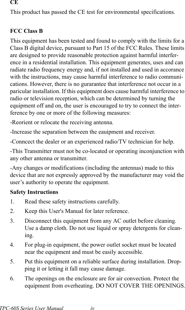

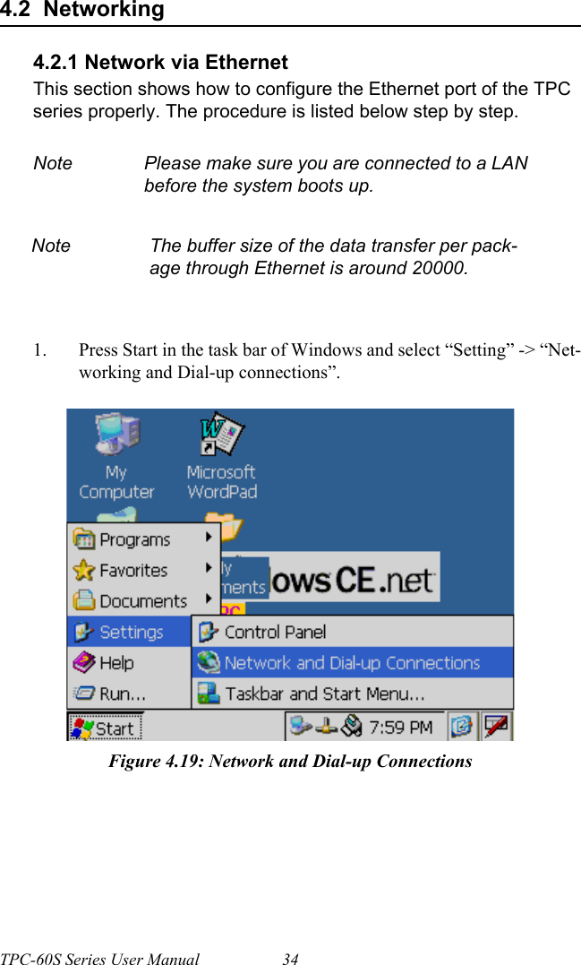
![33 Chapter 4 4.1.4 Other UtilitiesThere are other utilities provided in the panel computer. These utilities are command-line executed programs that do not have a graphical user interface. Please type the command names shown below in the command-line.Bright.exe [Level]:Sets the brightness level of the display. The parameter is from 1 to 10.Buzzer.exe [frequency] [duration]:Plays a beep. Use parameters to decide the frequency (Unit: Hz) and duration (Unit: ms). If you don’t use any parameters, the default fre-quency is 350 Hz and default duration is 30 ms.Contrast.exe [Level]:Sets the contrast of the display. The parameter is from 1 to 10.RegSave.exe [-s]:Saves registry settings. If you use “RegSave.exe –s”, no message box is displayed whether you are successful or fail. Reboot.exe:Saves the registry settings and reboots the panel computer.Screen.exe [on/off]:Turns the display on/off. Use “Screen.exe on” to turn on and “Screen.exe off” to turn off the display.Iesample.exe [-n] [-f] [ip address/ folder name]:Open the Internet Explorer. Use "Iesample.exe -n" to close the scroll bar. Use "Iesamples.exe -f" to active the full screen. The three parameters can be blank.](https://usermanual.wiki/Advantech-Co/TPC-61S/User-Guide-604814-Page-45.png)
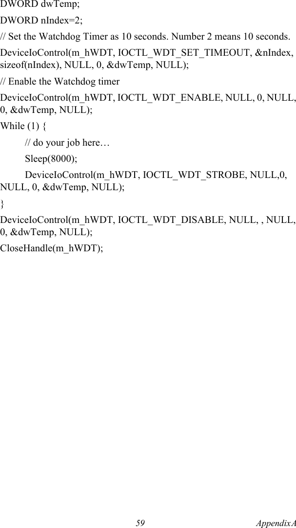
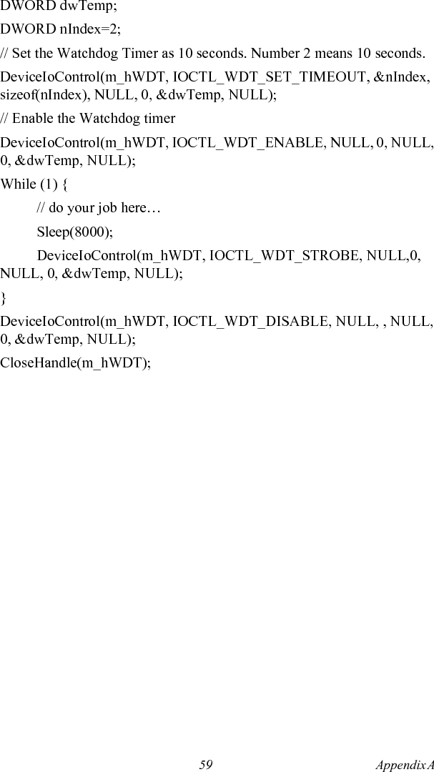
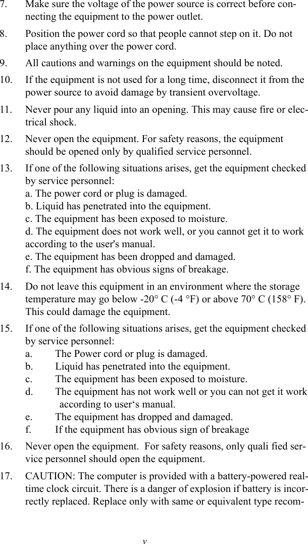
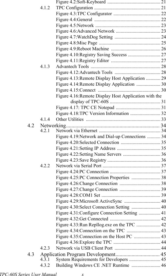
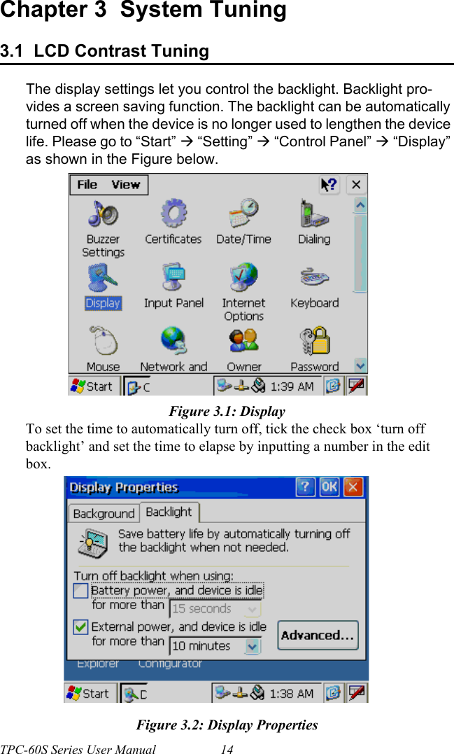
![TPC-60S Series User Manual 54Appendix A Watchdog Timer ProgrammingThere is a built-in watchdog timer in the TPC-60S series. You can access it through the WIN32 API. TPC-60S panel computers provide a WDT driver to allow users to enable/disable the Watchdog timer. The driver name is “WDT1:”. Programmers must open this driver before using the resources. Then programmers can use DeviceIOControl functions to enable/disable Watchdog timer. The introduction below includes the DeviceIOControl, the definition of the parameter and an example.A.1 DeviceIOControlThis function sends a control code directly to a specified device driver, causing the corresponding device to perform the specified operation.BOOL DeviceIoControl(HANDLE hDevice,DWORD dwIoControlCode,LPVOID lpInBuffer,DWORD nInBufferSize,LPVOID lpOutBuffer,DWORD nOutBufferSize,LPDWORD lpBytesReturned,LPOVERLAPPED lpOverlapped );Parameters:• hDevice[in] Handle to the device that is to perform the operation. Call the Cre-ateFile function to obtain a device handle.• dwIoControlCode[in] Specifies the control code for the operation. This value identifies the specific operation to be performed and the type of device on which the operation is to be performed. No specific values are defined for the dwIoControlCode parameter. However, the writer of a custom device driver can define IOCTL_XXXX control codes, per the CTL_CODE macro. These control codes can then be advertised, and an application can use these control codes with DeviceIoControl to perform driver-specific functions.](https://usermanual.wiki/Advantech-Co/TPC-61S/User-Guide-604814-Page-66.png)
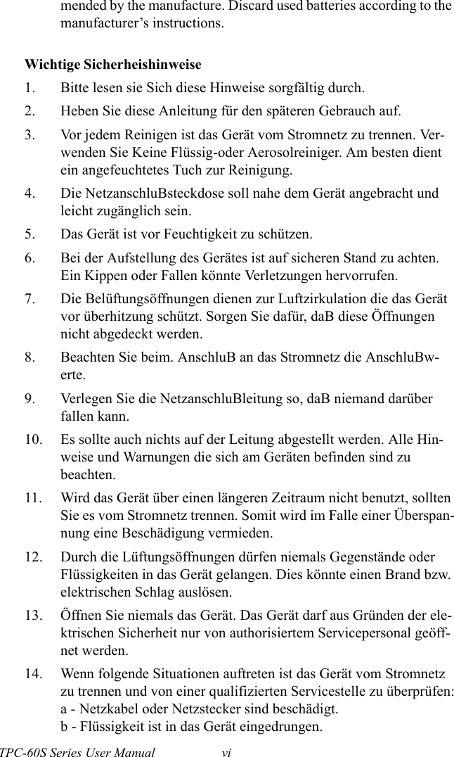
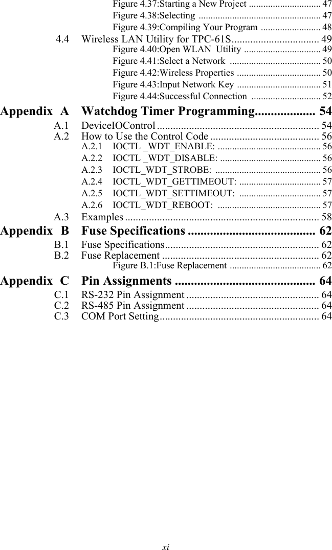
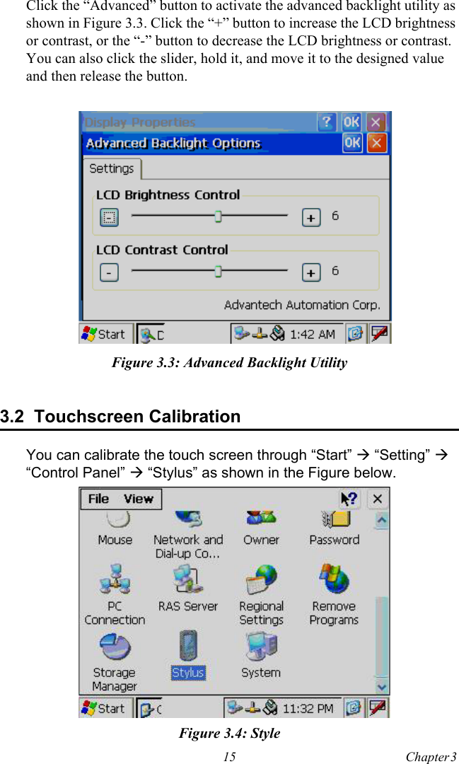
![55 Appendix A • lpInBuffer[in] Long pointer to a buffer that contains the data required to perform the operation. This parameter can be NULL if the dwIoControlCode parameter specifies an operation that does not require input data.• nInBufferSize[in] Size, in bytes, of the buffer pointed to by lpInBuffer.• lpOutBuffer[out] Long pointer to a buffer that receives the operation’s output data. This parameter can be NULL if the dwIoControlCode parameter speci-fies an operation that does not produce output data.• nOutBufferSize[in] Size, in bytes, of the buffer pointed to by lpOutBuffer.• lpBytesReturned[out] Long pointer to a variable that receives the size, in bytes, of the data stored into the buffer pointed to by lpOutBuffer. The lpBytesRe-turned parameter cannot be NULL. Even when an operation produces no output data, and lpOutBuffer can be NULL, the DeviceIoControl function makes use of the variable pointed to bylpBytesReturned. After such an operation, the value of the variable is without meaning.• lpOverlapped[in] Ignored; set to NULL.• Return ValuesNonzero indicates success. Zero indicates failure. To get extended error information, call GetLastError.](https://usermanual.wiki/Advantech-Co/TPC-61S/User-Guide-604814-Page-67.png)
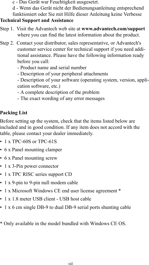
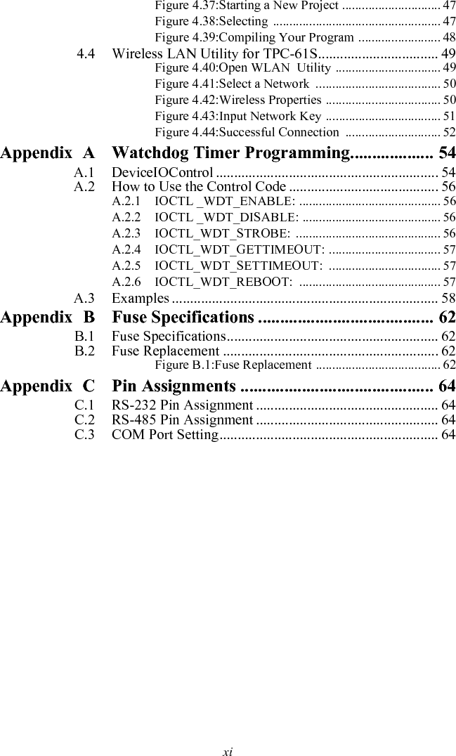
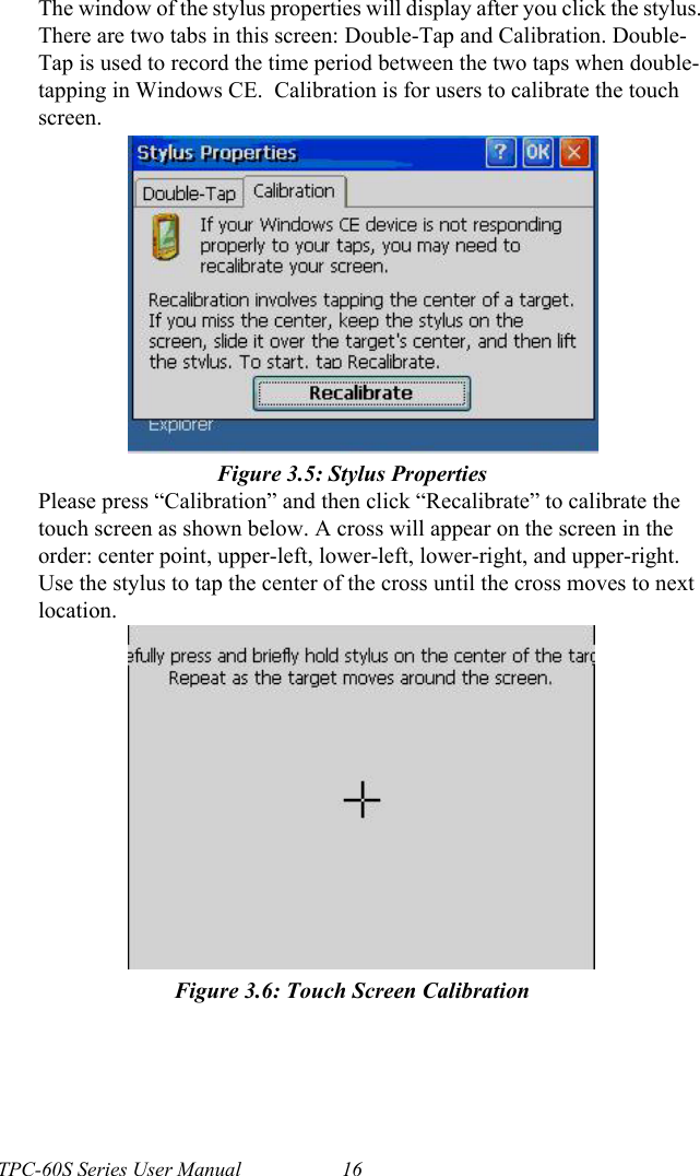
![TPC-60S Series User Manual 58A.3 Examples#define WDT_CODE(ID) CTL_CODE(FILE_DEVICE_UNKNOWN, ID, METHOD_BUFFERED, FILE_ANY_ACCESS)#define IOCTL_WDT_ENABLE WDT_CODE (0x900)#define IOCTL_WDT_DISABLE WDT_CODE(0x901)#define IOCTL_WDT_STROBE WDT_CODE(0x902)#define IOCTL_WDT_GET_TIMEOUT WDT_CODE(0x903)#define IOCTL_WDT_SET_TIMEOUT WDT_CODE(0x904)#define IOCTL_WDT_REBOOT WDT_CODE(0x905)// For compatibility reasons, you can define IOCTL as below:// #define IOCTL_WDT_ENABLE 0x1001// #define IOCTL_WDT_DISABLE 0x1002// #define IOCTL_WDT_STROBE 0x1003// #define IOCTL_WDT_GETTIMEOUT 0x1004// #define IOCTL_WDT_SETTIMEOUT 0x1005// #define IOCTL_WDT_REBOOT 0x1006HANDLE m_hWDT=NULL;TCHAR szClassName[60];// assign the WDT driver namewsprintf(szClassName, TEXT("WDT1:"));// Open the WDT driverm_hWDT = CreateFile(szClassName, GENERIC_READ GENERIC_WRITE, 0, NULL, OPEN_EXISTING, FILE_ATTRIBUTE_NORMAL, NULL);if ( m_hWDT == INVALID_HANDLE_VALUE ) {DebugMsg(CString("WDT driver fail"));return;}](https://usermanual.wiki/Advantech-Co/TPC-61S/User-Guide-604814-Page-70.png)