Advantech Co TREK-550 Computer User Manual
Advantech Co Ltd Computer
UserManual.wiki
>
Advantech Co
>
TREK 550 User Manual
Users Manual
Navigation menu
Upload a User Manual
Namespaces
Wiki Guide
HTML
PDF
Info
Views
User Manual
Discussion / Help
Navigation

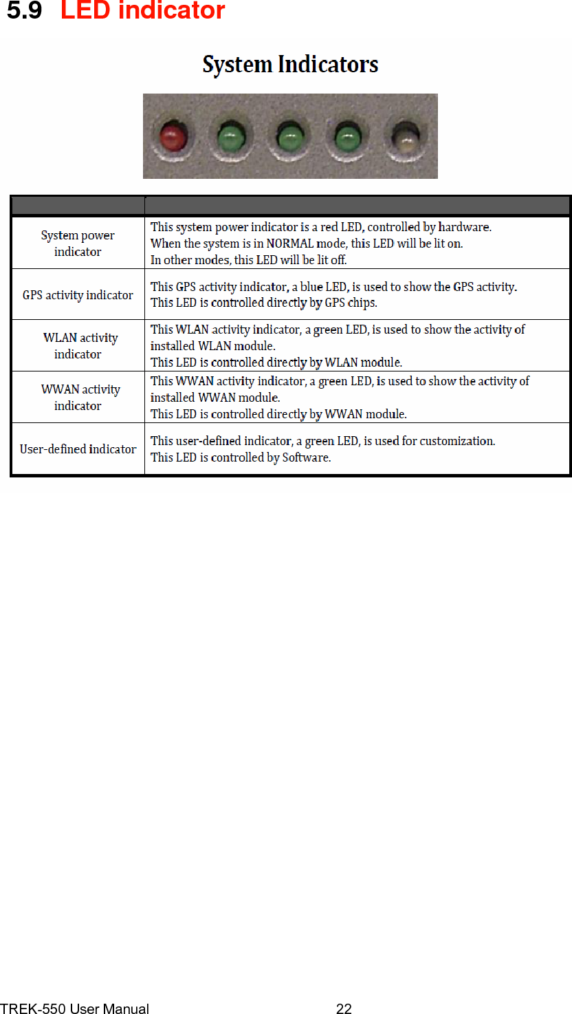
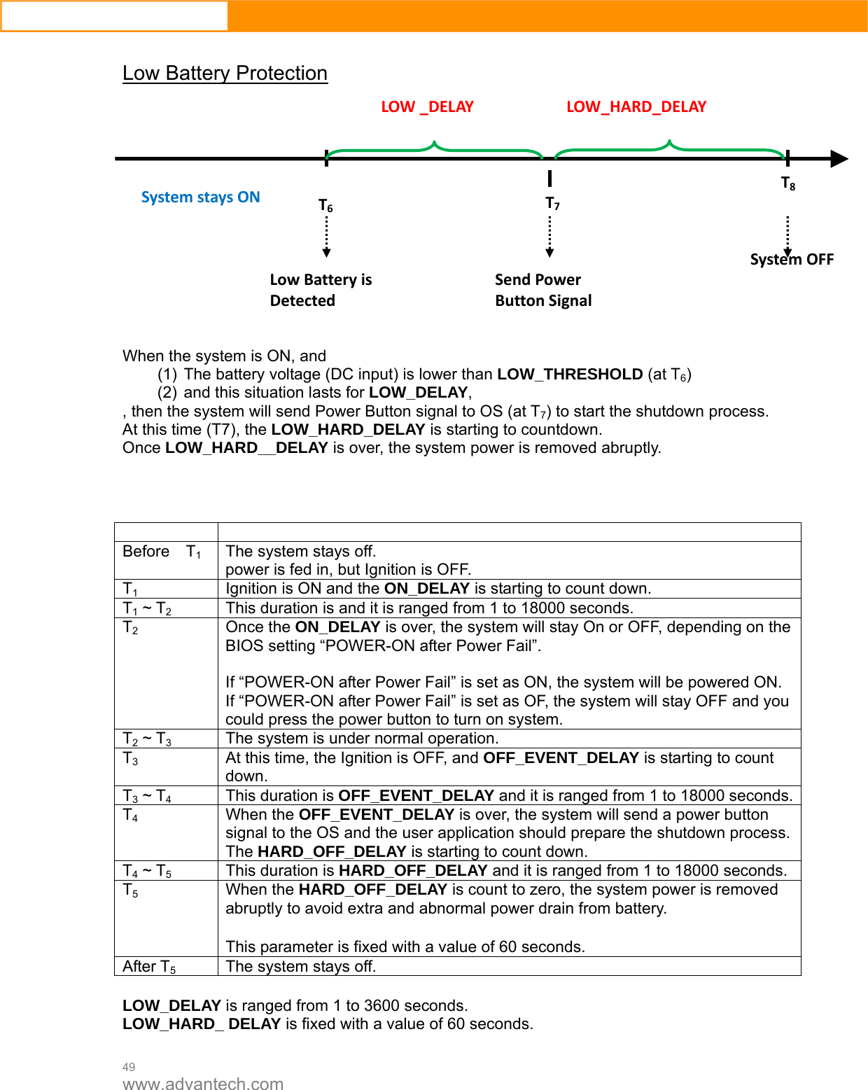
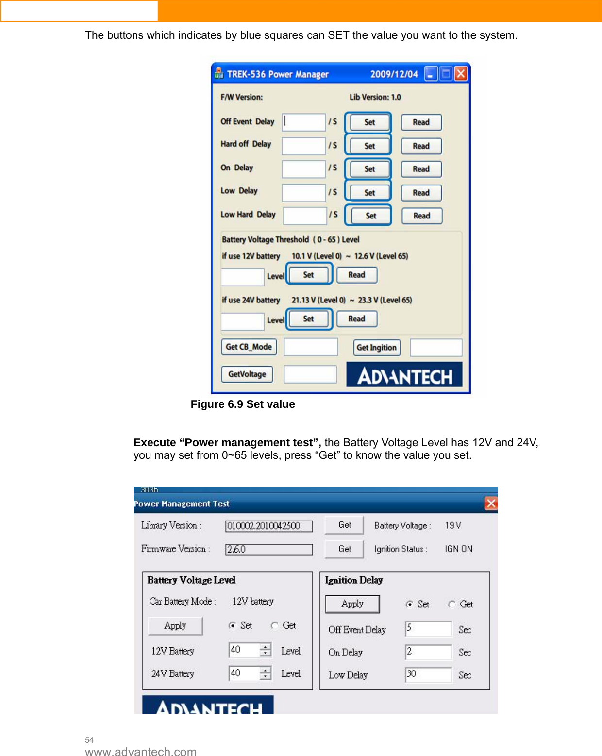
![43 www.advantech.com 6.1Introduction Tomake the hardware easiertoaccessfor programmers, Advantech has developedan demo program in order to let customer test the functions on TREK-550. This document describes detailed information for each Advantech demo program so thatapplication developers can becomemorefamiliar with using them. For technical support, contact Advantech application engineers worldwide.For news updates, visit our website:www.advantech.com 6.1.1Execute J1939 demo program Thissection explainshow to install theAdvantech demo program in Windows XP Pro / Embedded. 1. Execute the test program called “IMC_Demo” Figure 6. 1 2. Click J1939: customer may connect directly to the truck; we use a simulator board below to explain how J1939 protocol can be executed. First, connect to the simulator board to TREK-550 CAN port and console PC, once the simulator is powered on (connect to the truck), you can start getting the data, just click [Read], you may get the data you need from the simulator, click [Read], you may transfer the data to Console Smulator vendor name: TREK-550 User Manual22](https://usermanual.wiki/Advantech-Co/TREK-550/User-Guide-1737391-Page-38.png)
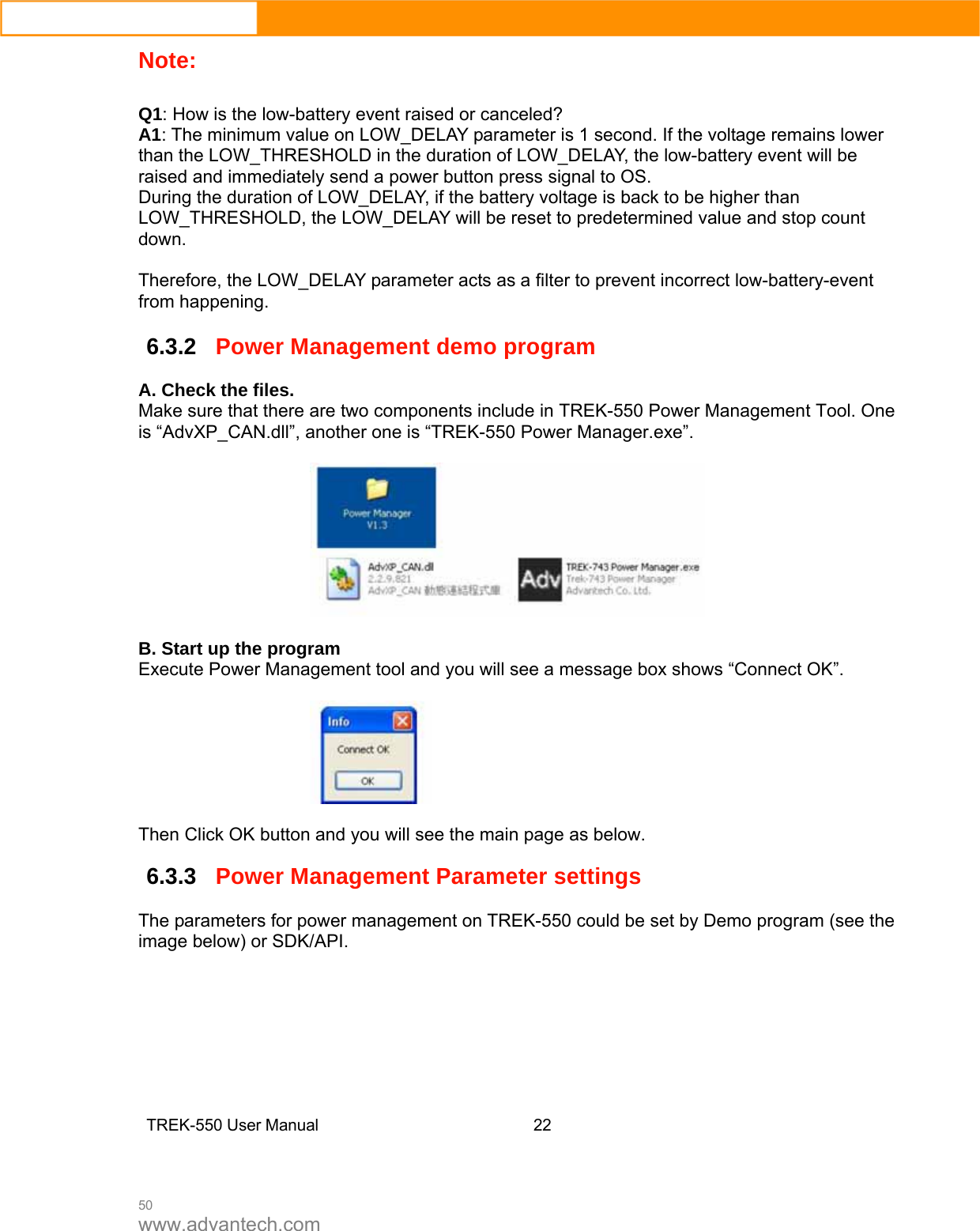
![45 www.advantech.com 6.1.2CAN Test 1. CAN: Console PC, install [PCAN_USB-to-CAN] test program, and use USB to CAN fixture to connect to TREK-550 CAN port. 2. Execute PCAN-View USB→ Set Baud rate 250kBit/s→ Select [Extended]→OK→ Transmit → New → ID(Hex) key in number → Data key in any number→[Period] key in 100ms→Click [Extended Frame]→OK. See below figure 6. Figure 6. 11 Figure 6. 12 TREK-550 User Manual22](https://usermanual.wiki/Advantech-Co/TREK-550/User-Guide-1737391-Page-40.png)
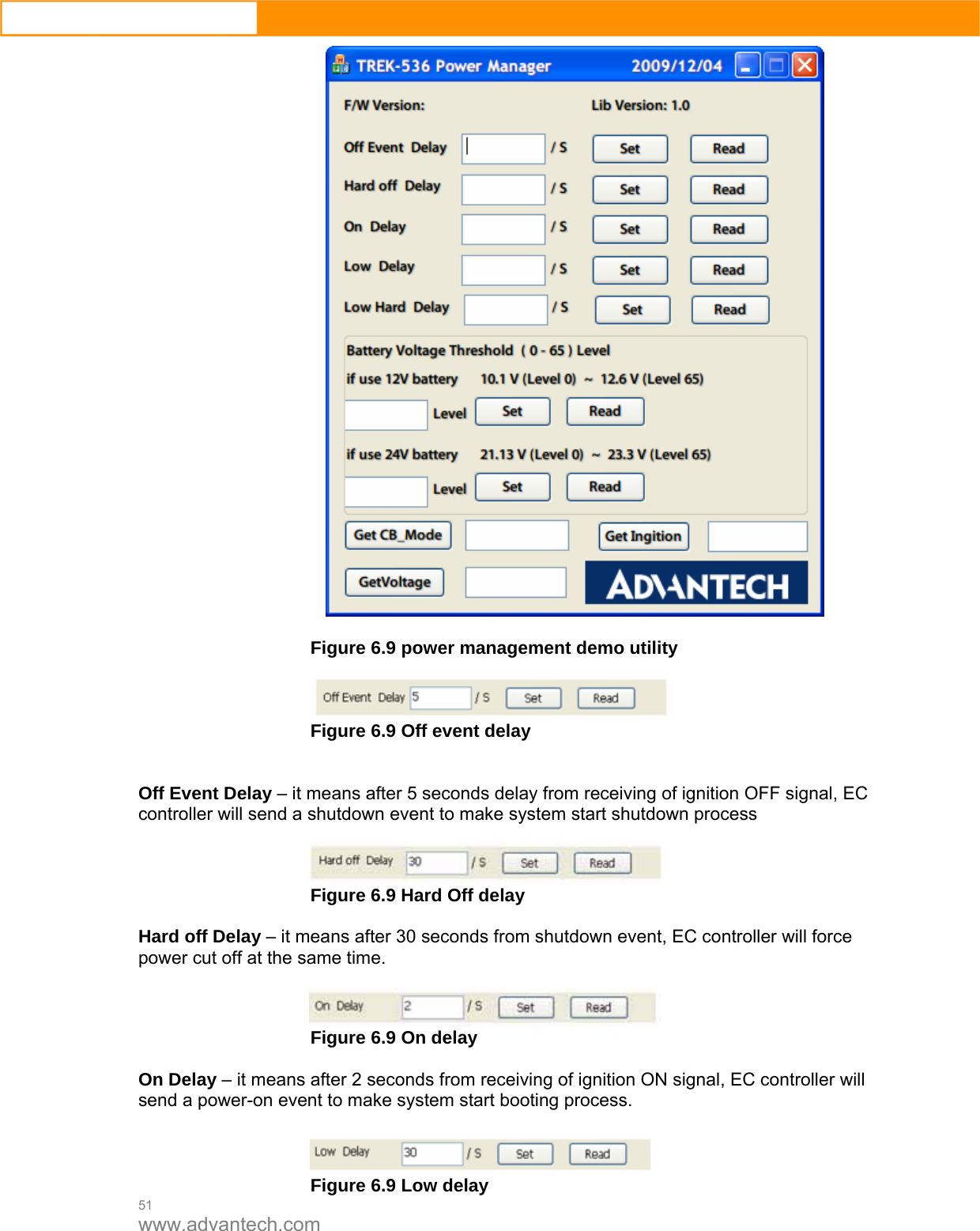
![46 www.advantech.com Figure 6. 13 3. Then you may read the data of TREK-550 from Console PC, in the same time, you may also press [Write Data] to write to Console PC. As for Filter Message, it can filter out the message you don’t need, and keep the message you need. See below Figure 6. Figure 6. 14 TREK-550 User Manual22](https://usermanual.wiki/Advantech-Co/TREK-550/User-Guide-1737391-Page-41.png)
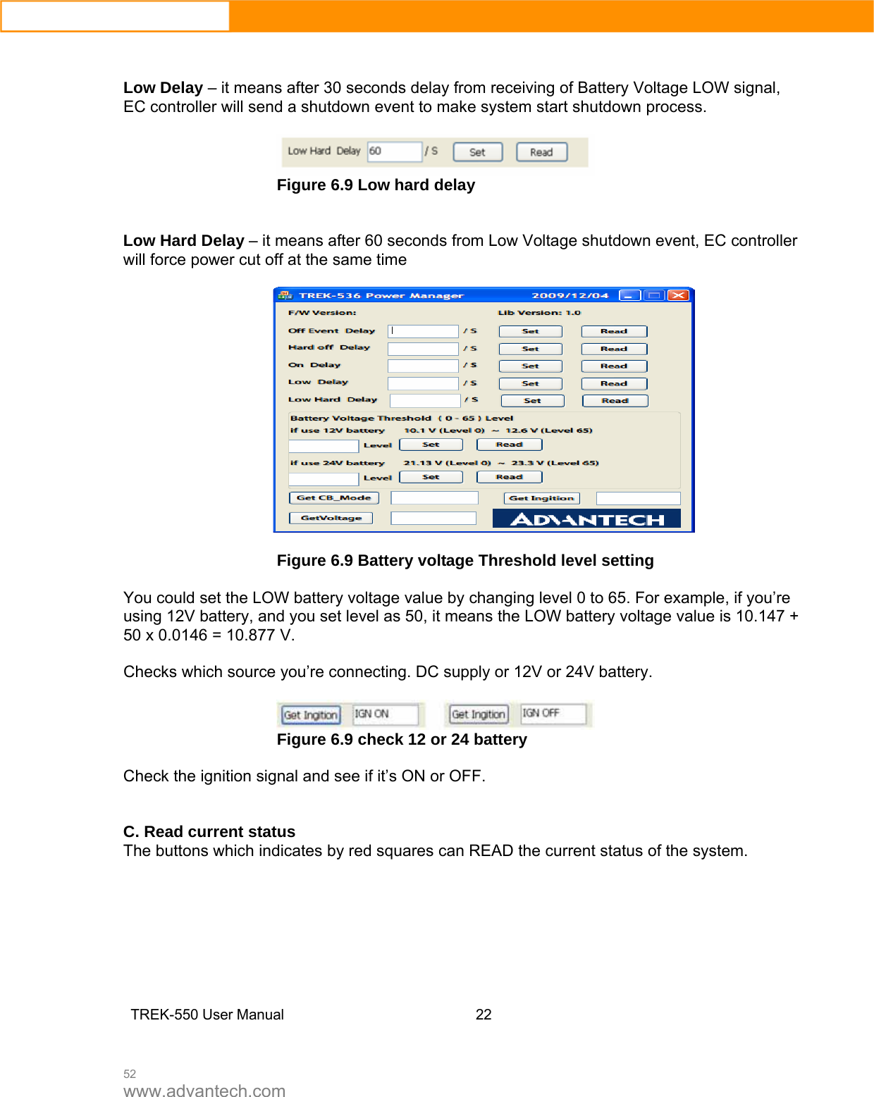

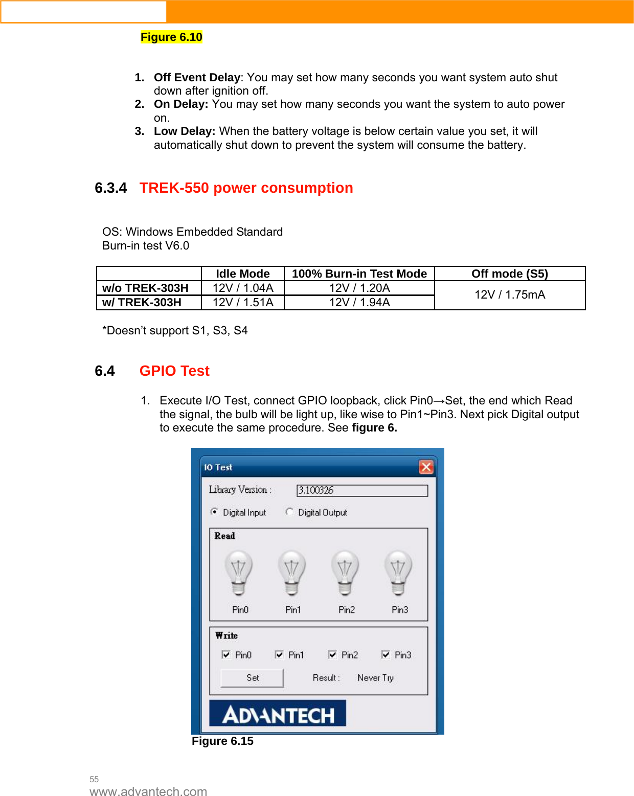
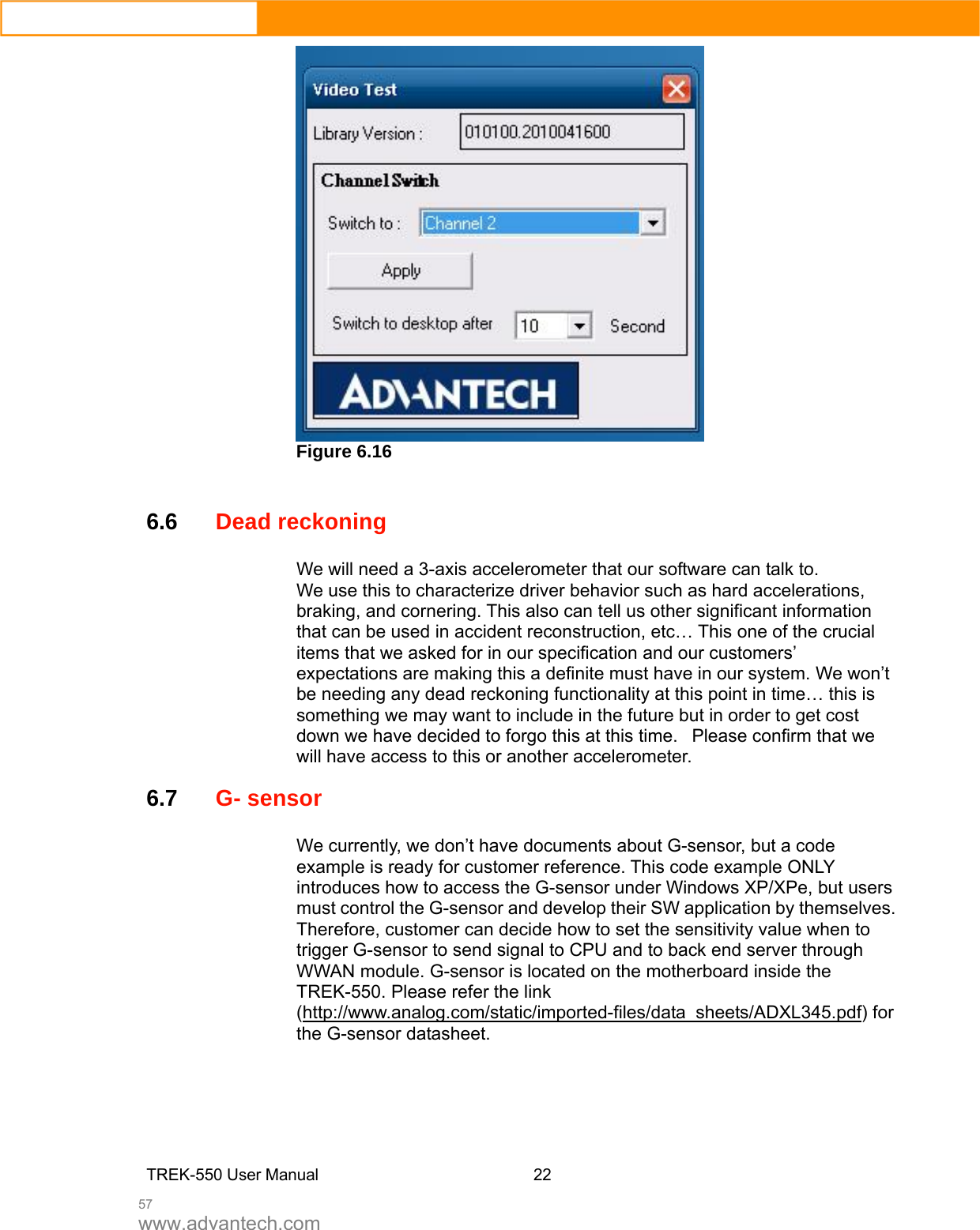
![56 www.advantech.com a. Digital Output Î isolated relay driver output b. Digital Input Î isolated dry contact input Figure 6.15 Digital in Figure 6.15 Digital out 6.5Video in Test There are two video in, please connect camera on each port, CAM1 & CAM2, choose Channel 1 on [Switch to], then panel will show the image which camera1 has taken, it will recover to the same status after 10 sec, then change to Channel 2, Panel will show what appears on camera2, and come back to the same status after 10 sec.](https://usermanual.wiki/Advantech-Co/TREK-550/User-Guide-1737391-Page-51.png)