Advantech Co TREK530LTE Computer User Manual V4 12 EV User Manual
Advantech Co Ltd Computer V4 12 EV User Manual
UserManual.wiki
>
Advantech Co
>
TREK530LTE User Manual
>
User Manual
Contents
1.
User Manual
2.
Users Manual
User Manual
Navigation menu
Upload a User Manual
Namespaces
Wiki Guide
HTML
PDF
Info
Views
User Manual
Discussion / Help
Navigation
![[鍵入文字] Chapter 2 System Setup 2.1 A Quick Tour of the TREK-530 Computer Before starting to set up TREK-530, take a moment to become familiar with the locations and functions of the connectors and ports, which are illustrated in the figures below. Figure 2.1 Rear view of TREK-530 2.2 Installation Procedures 2.2.1 Installing SIM card Remove WWAN extension module enclosed I/O door screw then open the rubber door on left side. Then can install SIM Card directly. Figure 2.3 Installing SIM card](https://usermanual.wiki/Advantech-Co/TREK530LTE.User-Manual/User-Guide-3996004-Page-13.png)
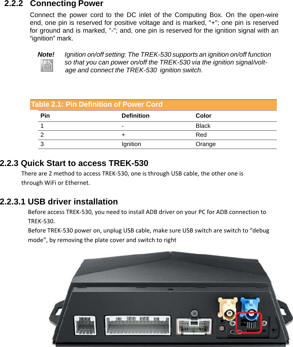
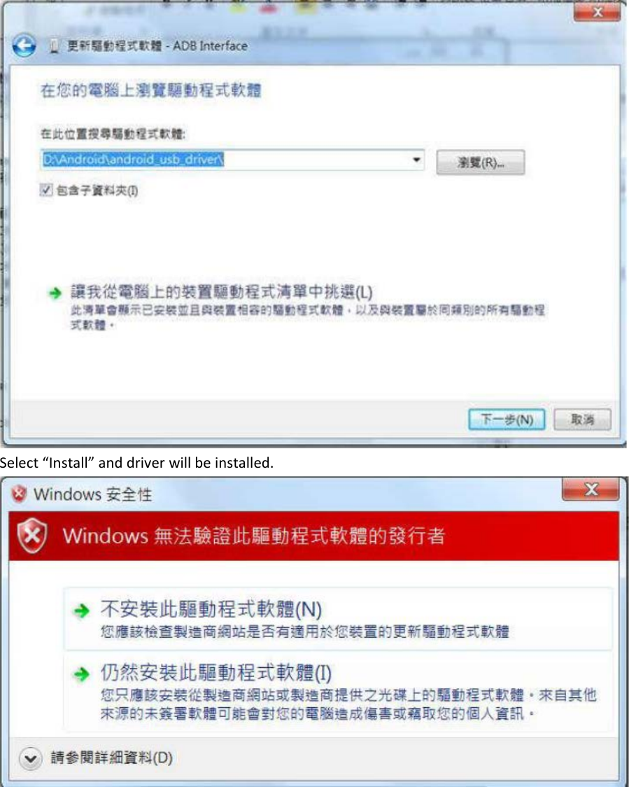
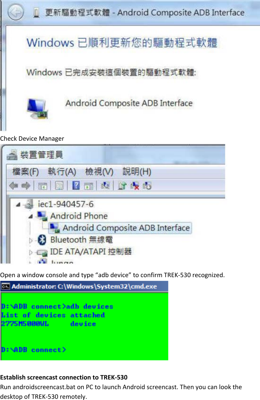
![Qualcomm ADB driver install Environment setup - Windows 7/8 32 / 64bit - Android_USB_Driver.7z - Unzip Android_USB_Driver.7z - [TREK-530] Make sure device is off. - [TREK-530] Switch USB switch to USB debug side - Power on device - After 10 sec, plug-in USB cable - Check DeviceManager in your PC, found a un-known device as following pic. Right click it and select “Updated driver” than select “Browse my computer…” Browse to driver folder and click “Next”](https://usermanual.wiki/Advantech-Co/TREK530LTE.User-Manual/User-Guide-3996004-Page-15.png)
![2.2.3.2 WiFi & Ethernet auto configure Download a file “trek530_adv.cfg” from Advantech support website. Change file setting in trek530_adv.cfg Save trek530_adv.cfg in USB or SDCard storage Plug storage into TREK530 WiFi Setting – [WIFI] => Setting for WiFi – SSID: => SSID name – WTYPE: => Security Mode OPEN WEP WPAPSK (Include WPA/WPA2 - AES/TKIP) – PW: => Password (No Need if type is “OPEN”) Ex: Ethernet Setting – [ETH] => Setting for Ethernet – ETYPE: => Type of Ethernet](https://usermanual.wiki/Advantech-Co/TREK530LTE.User-Manual/User-Guide-3996004-Page-18.png)
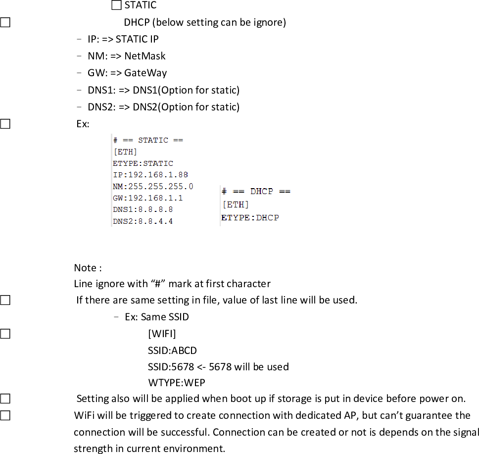
![ STATIC DHCP (below setting can be ignore) – IP: => STATIC IP – NM: => NetMask – GW: => GateWay – DNS1: => DNS1(Option for static) – DNS2: => DNS2(Option for static) Ex: Note : Line ignore with “#” mark at first character If there are same setting in file, value of last line will be used. – Ex: Same SSID [WIFI] SSID:ABCD SSID:5678 <- 5678 will be used WTYPE:WEP Setting also will be applied when boot up if storage is put in device before power on. WiFi will be triggered to create connection with dedicated AP, but can’t guarantee the connection will be successful. Connection can be created or not is depends on the signal strength in current environment.](https://usermanual.wiki/Advantech-Co/TREK530LTE.User-Manual/User-Guide-3996004-Page-19.png)
![4 Installation of the MRM SDK You can install SDK(MRM Services) to your device by follow the steps below 1. Unzip the SDK package Extract the SDK package zip file with password. The password is same as the filename. 2. Install MRM Services (mrm_service.apk) ( NOTE: This step is only necessary for IVCP and SDP function. You can skip this step if you only need VCIL functions ) Connect device to you computer with ADB. Execute the script install_mrm_service.bat in [SDK_Pacakge]/bin/ The script will execute the following ADB command: adb install -r .\mrm_service.apk After installed, you will get the following package in your devices There will also be an MRM Service Console APP named "MRM" in the APP list. This is a utility for](https://usermanual.wiki/Advantech-Co/TREK530LTE.User-Manual/User-Guide-3996004-Page-28.png)
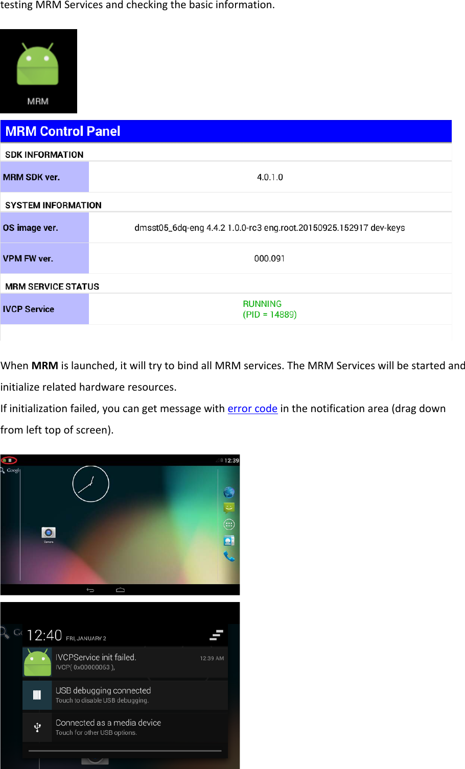
![In the MRM, the service status will should be shown with the service process ID. The status will be one of the followings: o RUNNING Service process is working correctly. ex: o NOT_INITIALIZED Service process exists but the hardware resources can not be initialized. In this status, the IVCP APIs can not work properly. You can find the error code message in the notification area. ex: o UNKNOWN Service process exists but the initialization status can not be confirmed. The error code will be also shown. (For the definition of error codes, please refer to the IVCP, VCIL, SDP User Manual) ex: o STOP Service process does not exist. ex: 3. Import MRM Service Client APIs Library ( NOTE: This step is only necessary for IVCP and SDP function. You can skip this step if you only need VCIL functions ) To access MRM Service from your APP, you must import the MRM Service Client API lib into you project. Please find the MrmServiceClientAPI.jar and MrmDef.jar in the MRM SDK package. Copy the libraries to the directory /[Module Name]/libs/ in you Android Studio project (the default](https://usermanual.wiki/Advantech-Co/TREK530LTE.User-Manual/User-Guide-3996004-Page-30.png)
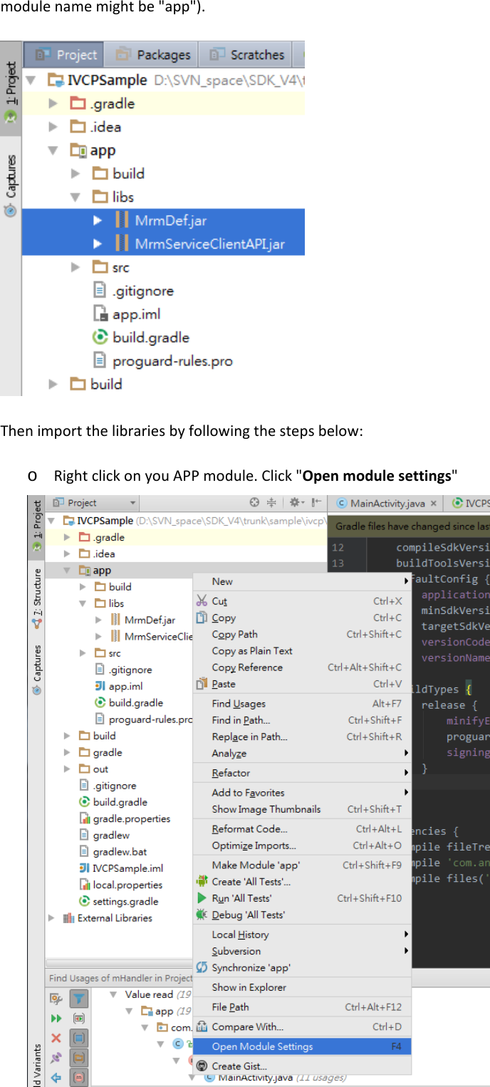
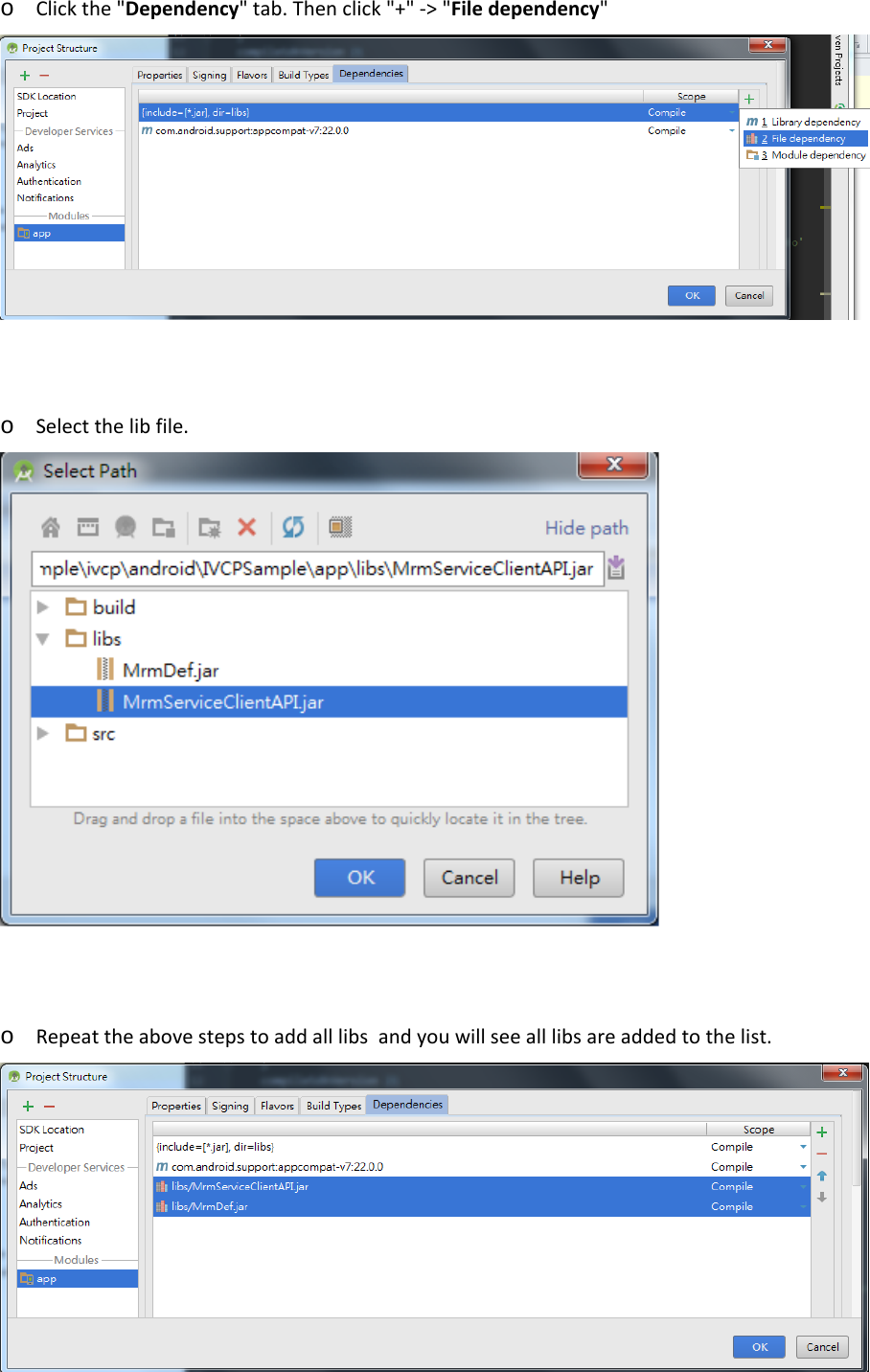
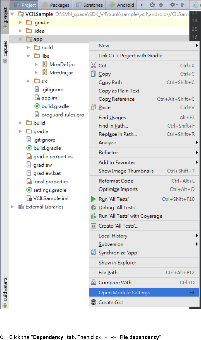
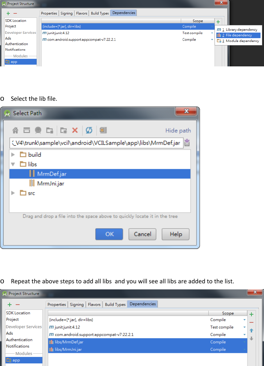
![4. Import VCIL APIs Library ( NOTE: This step is only necessary for VCIL functions ) To access VCIL functions from your APP, you must import the VCIL libraries into you project. Please find the MrmJni.jar, MrmDef.jar and jniLibs/ folder in the MRM SDK package. Copy the MrmJni.jar, MrmDef.jar to the directory /[Module Name]/libs/ in your Android Studio project (the default module name might be "app") and copy the jniLibs/ folder to the directory /[Module Name]/src/main/ . Then import the Java libraries by following the steps below: o Right click on you APP module. Click "Open module settings"](https://usermanual.wiki/Advantech-Co/TREK530LTE.User-Manual/User-Guide-3996004-Page-33.png)
![5 Install Prebuilt Sample Apps The prebuilt sample is placed in [SDK_Pacakge]/bin/samples/ . Execute the script install_sample_apps.bat to install to your device. The script will execute the following ADB command: adb install -r .\IVCPSample.apk adb install -r .\SDPSample.apk adb install -r .\VCILSample.apk Please note that you must install the MRM Services (mrm_service.apk) fist or the sample APPs will not work.](https://usermanual.wiki/Advantech-Co/TREK530LTE.User-Manual/User-Guide-3996004-Page-36.png)