Advantech Co TREK530LTE Computer User Manual V4 12 EV User Manual
Advantech Co Ltd Computer V4 12 EV User Manual
Contents
- 1. User Manual
- 2. Users Manual
Users Manual

User Manual
TREK-530
Computer

TREK-530 User Manual
Copyright
The documentation and the software included with this product are copyrighted 2017
by Advantech Co., Ltd. All rights are reserved. Advantech Co., Ltd. reserves the right
to make improvements in the products described in this manual at any time without
notice. No part of this manual may be reproduced, copied, translated or transmitted
in any form or by any means without the prior written permission of Advantech Co.,
Ltd. Information provided in this manual is intended to be accurate and reliable. How-
ever, Advantech Co., Ltd. assumes no responsibility for its use, nor for any infringe-
ments of the rights of third parties, which may result from its use.
Acknowledgements
Qualcomm is trademarks of Qualcomm Incorporated.
Android is registered trademarks of Google LLC.
All other product names or trademarks are properties of their respective owners.
Product Warranty (2 years)
Advantech warrants to you, the original purchaser, that each of its products will be
free from defects in materials and workmanship for two years from the date of pur-
chase.
This warranty does not apply to any products which have been repaired or altered by
persons other than repair personnel authorized by Advantech, or which have been
subject to misuse, abuse, accident or improper installation. Advantech assumes no
liability under the terms of this warranty as a consequence of such events.
Because of Advantech’s high quality-control standards and rigorous testing, most of
our customers never need to use our repair service. If an Advantech product is defec-
tive, it will be repaired or replaced at no charge during the warranty period. For out-
of-warranty repairs, you will be billed according to the cost of replacement materials,
service time and freight. Please consult your dealer for more details.
If you think you have a defective product, follow these steps:
1. Collect all the information about the problem encountered. (For example, CPU
speed, Advantech products used, other hardware and software used, etc.) Note
anything abnormal and list any onscreen messages you get when the problem
occurs.
2. Call your dealer and describe the problem. Please have your manual, product,
and any helpful information readily available.
3. If your product is diagnosed as defective, obtain an RMA (return merchandize
authorization) number from your dealer. This allows us to process your return
more quickly.
4. Carefully pack the defective product, a
fully-completed
Repair and Replacement
Order Card and a photocopy proof of purchase date (such as your sales receipt)
in a shippable container. A product returned without proof of the purchase date
is not eligible for warranty service.
5. Write the RMA number visibly on the outside of the package and ship it prepaid
to your dealer.
Part No. Edition 1
Apr 2018

TREK-530 User Manual
Declaration of Conformity
CE
This product has passed the CE test for environmental specifications. Test conditions
for passing included the equipment being operated within an industrial enclosure. In
order to protect the product from being damaged by ESD (Electrostatic Discharge)
and EMI leakage, we strongly recommend the use of CE-compliant industrial enclo-
sure products.
FCC Class B
Note: This equipment has been tested and found to comply with the limits for a Class
B digital device, pursuant to part 15 of the FCC Rules. These limits are designed to
provide reasonable protection against harmful interference in a residential installa-
tion. This equipment generates, uses and can radiate radio frequency energy and, if
not installed and used in accordance with the instructions, may cause harmful inter-
ference to radio communications. However, there is no guarantee that interference
will not occur in a particular installation. If this equipment does cause harmful interfer-
ence to radio or television reception, which can be determined by turning the equip-
ment off and on, the user is encouraged to try to correct the interference by one or
more of the following measures:
„
Reorient or relocate the receiving antenna
Increase the separation between the equipment and receiver.
Connect the equipment into an outlet on a circuit different from that to which the
receiver is connected.
Consult the dealer or an experienced radio/TV technician for help.
This device complies with Part 15 FCC Rules.
Operation is subject to the following two conditions.
(1) This device may not cause harmful interference , and
(2) The device must accept any interference received, including
interference may cause undesired operation.
FCC Caution :
Any changes or modifications not expressly approved by the party responsible for
compliance could void the user's authority to operate this equipment.
FCC RF Radiation Exposure Statement :
This device meets the government`s requirements for exposure to radio waves.
This device is designed and manufactured not to exceed the emission limits for
exposure to radio frequency(RF) energy set by the Federal Communications
Commission of the U.S. Government.
This device complies with FCC radiation exposure limits set forth for an uncontrolled
environment. In order to avoid the possibility of exceeding the FCC radio frequency
exposure limits, human proximity to the antenna shall not be less than 20cm (8
inches) during normal operation.
Changes or modifications not expressly approved by the party responsible for
compliance could void the user`s authority to operate the equipment.
.
TREK-530 User Manual
Technical Support and Assistance
1. Visit the Advantech web site at
http://support.advantech.com
where you can find
the latest information about the product.
2. Contact your distributor, sales representative, or Advantech's customer service
center for technical support if you need additional assistance. Please have the
following information ready before you call:
– Product name and serial number
– Description of your peripheral attachments
– Description of your software (operating system, version, application software,
etc.)
– A complete description of the problem
– The exact wording of any error messages

TREK-530 User Manual
Warnings, Cautions and Notes
Warning! Warnings indicate conditions, which if not observed, can cause personal
injury!
Caution! Cautions are included to help you avoid damaging hardware or losing
data. e.g.
There is a danger of a new battery exploding if it is incorrectly installed.
Do not attempt to recharge, force open, or heat the battery. Replace the
battery only with the same or equivalent type recommended by the man-
ufacturer. Discard used batteries according to the manufacturer's
instructions.
Note! Notes provide optional additional information.
Document Feedback
To assist us in making improvements to this manual, we would welcome comments
and constructive criticism. Please send all such - in writing to: support@advan-
tech.com
Packing List
Before setting up the system, check that the items listed below are included and in
good condition. If any item does not accord with the table, please contact your dealer
immediately.
Description
Q`ty
TREK-530 Computer
1
Power cable (2M)
1
LAN adaptor cable
1

Ordering Information
Part Number
Description
TREK-530-GWBADA20
TREK-530 Barebone w/ slot
TREK-530-LWBADA20
TREK-530 EU full config. w/ WLAN,BT,LTE,GNSS
TREK-530-LWBADB20
TREK-530 US full config. w/WLAN,BT,LTE,GNSS
Safety Instructions
1. Read these safety instructions carefully.
2. Keep this User Manual for later reference.
3. Disconnect this equipment from any AC outlet before cleaning. Use a damp cloth.
Do not use liquid or spray detergents for cleaning.
4. For plug-in equipment, the power outlet socket must be located near the equip- ment
and must be easily accessible.
5. Keep this equipment away from humidity.
6. Put this equipment on a reliable surface during installation. Dropping it or
letting it
fall
may cause damage.
7. Do not leave this equipment in an environment unconditioned where the storage
temperature under -40° C (-40° F) or above 85° C (185° F), it may damage the
equipment. Operating temperature: -20°C~65°C without battery.
8. Do not operate this equipment in an environment temperature may over
65°C(149° F). The surface temperature of plastic chassis may be hot.
9. Make sure the voltage of the power source is correct before connecting the
equipment to the power outlet.
10. Position the power cord so that people cannot step on it. Do not place anything over
the power cord. The voltage and current rating of the cord should be greater than the
voltage and current rating marked on the product.
11. All cautions and warnings on the equipment should be noted.
12. If the equipment is not used for a long time, disconnect it from the power source to
avoid damage by transient overvoltage.
13. Never pour any liquid into an opening. This may cause fire or electrical shock.
14. Never open the equipment. For safety reasons, the equipment should be
opened only by qualified service personnel.
15. If one of the following situations arises, get the equipment checked by service
personnel:
„
The power cord or plug is damaged.
„
Liquid has penetrated into the equipment.
„
The equipment has been exposed to moisture.
„
The equipment does not work well, or you cannot get it to work according to
the user's manual.
„
The equipment has been dropped and damaged.
„
The equipment has obvious signs of breakage.
16. CAUTION: The computer is provided with a battery-powered real-time clock cir- cuit.
There is a danger of explosion if battery is incorrectly replaced. Replace only with
same or equivalent type recommended by the manufacture. Discard used batteries
according to the manufacturers instructions.
17. This device complies with Part 15 of the FCC rules. Operation is subject to the
following two conditions:
(1) this device may not cause harmful interference, and

(2) this device must accept any interference received, including interference that may
cause undesired operation.
18. CAUTION: Always completely disconnect the power cord from your chassis
whenever you work with the hardware. Do not make connections while the power
is on. Sensitive electronic components can be damaged by sudden power surges.
19. CAUTION: Always ground yourself to remove any static charge before touching the
motherboard, backplane, or add-on cards. Modern electronic devices are very
sensitive to static electric charges. As a safety precaution, use a grounding wrist
strap at all times. Place all electronic components on a static-dissipative surface or in
a static-shielded bag when they are not in the chassis.
20. CAUTION: Any unverified component could cause unexpected damage. To ensure
the correct installation, please always use the components (ex. screws) provided
with the accessory box.
Safety Precaution - Static Electricity
Follow these simple precautions to protect yourself from harm and the products from
damage.
„
To avoid electrical shock, always disconnect the power from your PC chassis
before you work on it. Don't touch any components on the mainboard or other
cards while the system is on.
„
Disconnect power before making any configuration changes. The sudden rush
of power as you connect a jumper or install a card may damage sensitive elec-
tronic components.
This product is intended to be supplied by a Listed DC power source, rated 9-
32Vdc, 2A maximum and Tma 65 degree C, if need further assistance with
purchasing the DC power source, please contact Advantech for further information.
Warning! 1. Input voltage rated: 9 - 32 Vdc.
2. Transport: carry the unit with both hands and handle with care.
3. Maintenance: to properly maintain and clean the surfaces, use only
approved products or clean with a dry applicator.
4. SD/SIM card: Turn off the power before inserting or removing
the storage cards.
1. Tension d'entrée nominale: 9 - 32 Vdc.
2. Transport: portez l'appareil avec les deux mains et manipulez-le avec
précaution.
3. Entretien: pour bien entretenir et nettoyer les surfaces, n'utilisez que des
produits approuvés ou nettoyez-les avec un applicateur sec.
4. Carte SD / SIM: Mettez l'appareil hors tension avant de l'insérer ou de le
retirerles cartes de stockage.

Chapter 1
1 General Information
This chapter gives background
information on the TREK-530
Computer
Sections include:
„
Introduction
„
General Specifications
„
Dimensions

Chapter 1
General Information
1.1 Introduction
TREK-530 is a compact RISC-based in-vehicle computing box equipped with a Qualcomm® Snapdragon™ 212
quad-core ARM® Cortex™-A7 SoC, isolated DI/O, and two extension slots for optional expansion. Built-in
WLAN, Bluetooth, and GNSS modules offer enhanced connectivity, while periodic, digital input and WWAN
suspend/resume functionality
Supports remote monitoring, making TREK-530 ideal for logistics and fleet management. Moreover, the
system’s wide operating temperature range (-20 ~ 65 °C), support for 9-32Vdc power input, and compliance
with MIL-STD-810G and 5M3 shock/vibration standards ensures TREK-530 can withstand operation in harsh
environments.
1.2 General Specifications
Features
Qualcomm® Snapdragon™ 212 quad-core ARM® Cortex™-A7 SoC with Android 6.0 Marshmallow
Built-in WLAN, Bluetooth, and GNSS (including BeiDou) modules with external antenna via FAKRA
connector.
Modularized design with two extension slots for optional expansion (such as LTE 4G module or
battery) according to application requirements.
Multiple isolated DI/O; DI supports dry/wet contact and speed sensor inputs for measuring distance.
Compliant with MIL-STD-810G and 5M3 standards for shock/vibration tolerance.
Equipped with Advantech’s industrial Mobile Android Remote General Utilities for remote
management.

Specifications
System
Processor
Qualcomm® Snapdragon™ 212 APQ8009 quad-core ARM® Cortex™-A7
(1.3 GHz) SoC
Memory
2 GB
Storage
16 GB eMCP
1 x Externally accessible MicroSD (push-push type) with cover
Watchdog
Yes
RTC
Yes
O.S
Android 6.0 Marshmallow
RF
WiFi
IEEE 802.11 a/b/g/n dual band (2.4/5 GHz) (with external antenna via
FAKRA connector)
Bluetooth
Bluetooth V4.1 Class 1 (with external antenna via FAKRA connector)
GNSS
GPS, GLONASS, and AGPS (BeiDou upon request) support (with
external antenna via FAKRA connector)
WWAN
Sierra Wireless MC7304 via extension module (EU)
LTE: B1, B3, B7, B8, B20
Sierra Wireless MC7354 via extension module (US)
LTE: B2, B4, B5, B13, B17, B25 (external antenna via FAKRA connector)
WCDMA Band II, Band V, Band IV.
GPRS 850,1900,EGPRS 850,1900
Voice call
N/A
Wake-on-WWAN
N/A
SIM
1 SIM slot
External Antenna
1 x WLAN, 1 x WWAN Main, 1 x WWAN AUX & GPS (FAKRA connector)
Sensor
G-Sensor
Triple-axis accelerometer (±2g/4g/8g)
I/O
Generic I/O Port
(via automotive
connector)
1 x Mic-In, 1 x Line-Out
4 x Isolated DI (dry/wet contact)
2 x Isolated DO (open-collector output with relay driver)
1 x CAN bus (supports raw CAN, J1939, OBD-II/ISO 15765; firmware
configurable)
1 x J1708 (J1587)
1 x USB 2.0 Host
1 x 4-wire RS-232
1 x 4-wire RS-232/RS-485 (software configurable)
Standard I/O Port
1 x Micro USB OTG (Mini USB) with cover (for debugging)
1 x MicroSD slot with cover
Indicator
1x LED (Power)
Button
1x reset button with cover
Power
Reset
Yes
Input Voltage
9-32V DC
Backup Battery
(Optional)
3.6 V 2100 mAh
Mechanical
Dimensions (W x H x D)
140 x 110 x 50 mm (5.51 x 4.33 x 1.96 in)
Weight
410 g
IP Rating
IP54 with I/O cover
Environment
Regulation
E-Mark, ISO 7637-2, SAE J1455, PTCRB
EMC
CE,FCC
Safety
UL/cUL, CB, CCC
Operating Temperature
-20
°
C ~ 65 °C (-4 ~ 149 °F)
-10° C ~ 60° C (with battery discharge)
0° C ~ 45° C (with battery charge)
Storage Temperature
-40~85C (-40~185F) (without battery)
Shock/Vibration
MIL-STD-810G, SAE J1455
Chapter 1
General Information
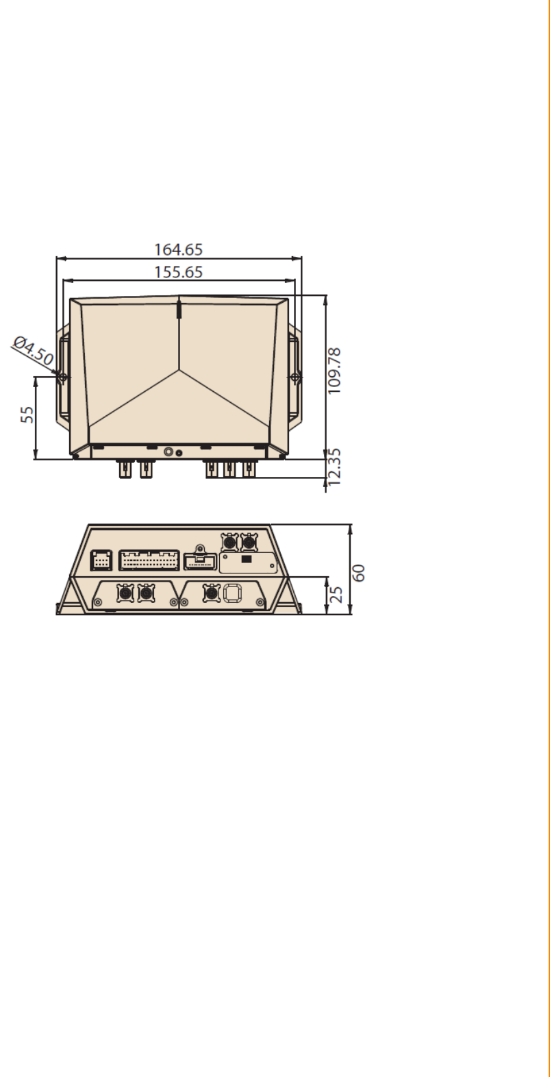
1.3 Dimensions
Figure 1.1 TREK-530 dimensions
Warning! Use suitable mounting apparatus to avoid risk of injury.ÚTTENTION:
Veuillez utiliser un système de montage approprié afin d'éviter tout risque de
blessure.ÐFixed VESA screw specification: M4 ; Screws depth: 10 mm. (Min)_

Chapter 2
2 System Setup
This chapter details system setup
on TREK-530
Sections include:
A Quick Tour of the Computer
Box
Installation Procedures
Quick Start to access TREK-530
[鍵入文字]
Chapter 2
System Setup
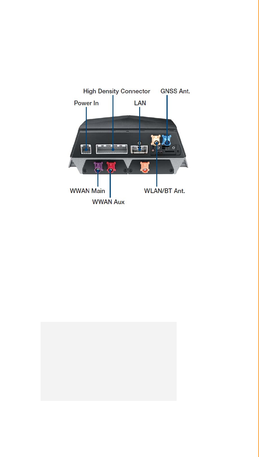
2.1 A Quick Tour of the TREK-530 Computer
Before starting to set up TREK-530, take a moment to become familiar with the
locations and functions of the connectors and ports, which are illustrated in the
figures below.
Figure 2.1 Rear view of TREK-530
2.2 Installation Procedures
2.2.1 Installing SIM card
Remove WWAN extension module enclosed I/O door screw then open the rubber
door on left side. Then can install SIM Card directly.
Figure 2.3 Installing SIM card
2.2.2 Connecting Power
Connect the power cord to the DC inlet of the Computing Box. On the open-wire
end, one pin is reserved for positive voltage and is marked, "+"; one pin is reserved
for ground and is marked, "-"; and, one pin is reserved for the ignition signal with an
“ignition” mark.
Note! Ignition on/off setting: The TREK-530 supports an ignition on/off function
so that you can power on/off the TREK-530 via the ignition signal/volt-
age and connect the TREK-530 ignition switch.
Table 2.1: Pin Definition of Power Cord
Pin Definition Color
1
-
Black
2
+
Red
3
Ignition
Orange
2.2.3 Quick Start to access TREK-530
There are 2 method to access TREK-530, one is through USB cable, the other one is
through WiFi or Ethernet.
2.2.3.1 USB driver installation
Before access TREK-530, you need to install ADB driver on your PC for ADB connection to
TREK-530.
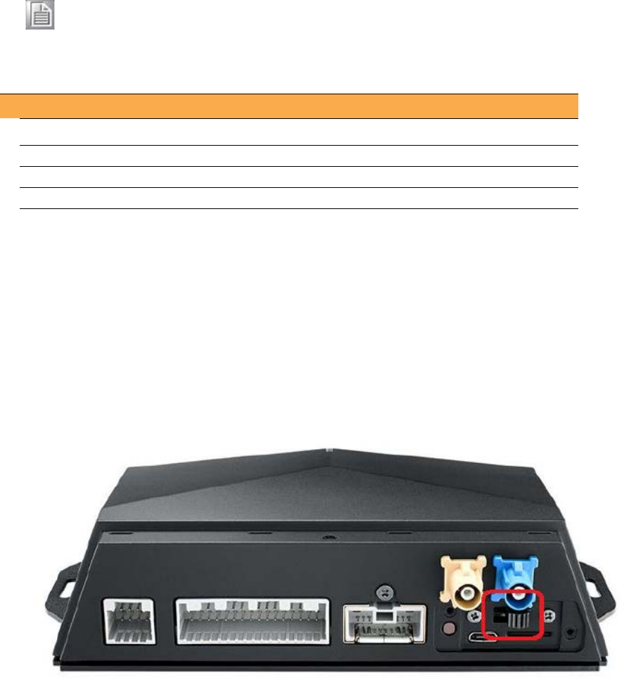
Before TREK-530 power on, unplug USB cable, make sure USB switch are switch to “debug
mode”, by removing the plate cover and switch to right
Qualcomm ADB driver install
Environment setup
- Windows 7/8 32 / 64bit
- Android_USB_Driver.7z
- Unzip Android_USB_Driver.7z
- [TREK-530] Make sure device is off.
- [TREK-530] Switch USB switch to USB debug side
- Power on device
- After 10 sec, plug-in USB cable
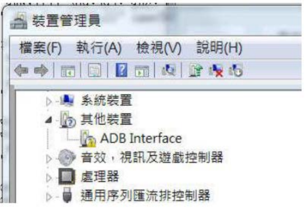
- Check DeviceManager in your PC, found a un-known device as following pic.
Right click it and select “Updated driver” than select “Browse my computer…”
Browse to driver folder and click “Next”
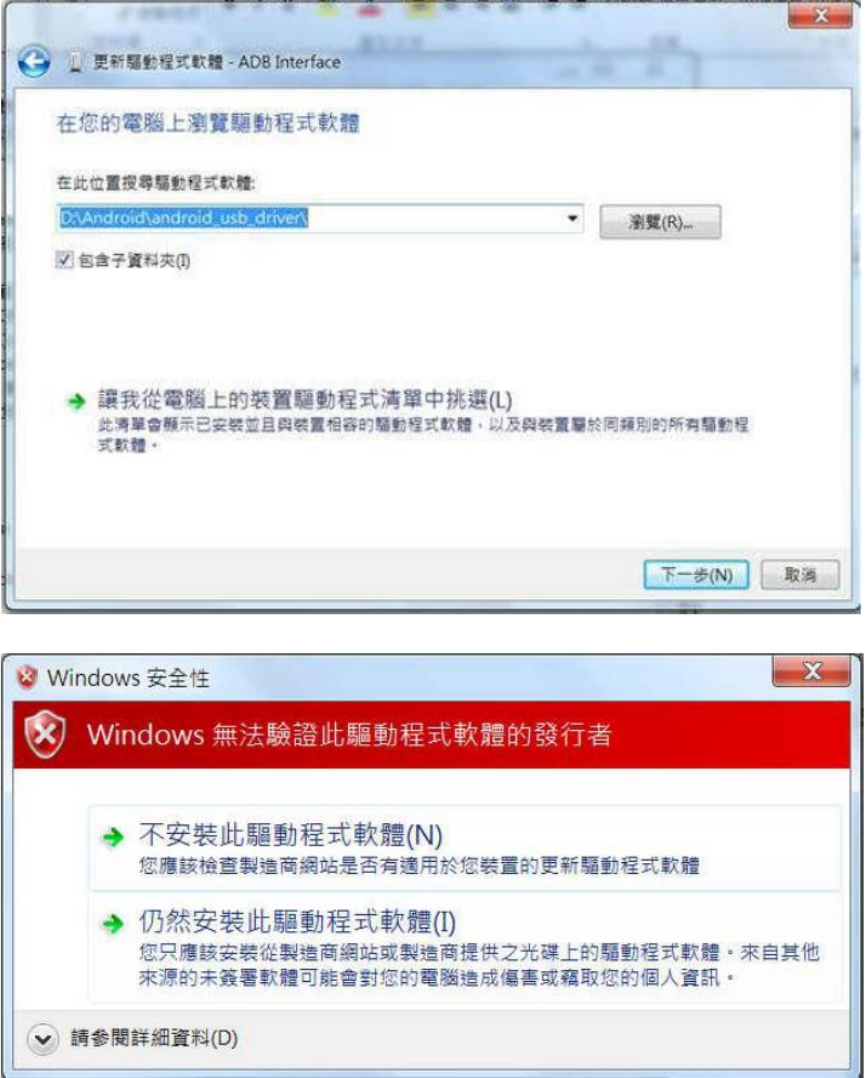
Select “Install” and driver will be installed.
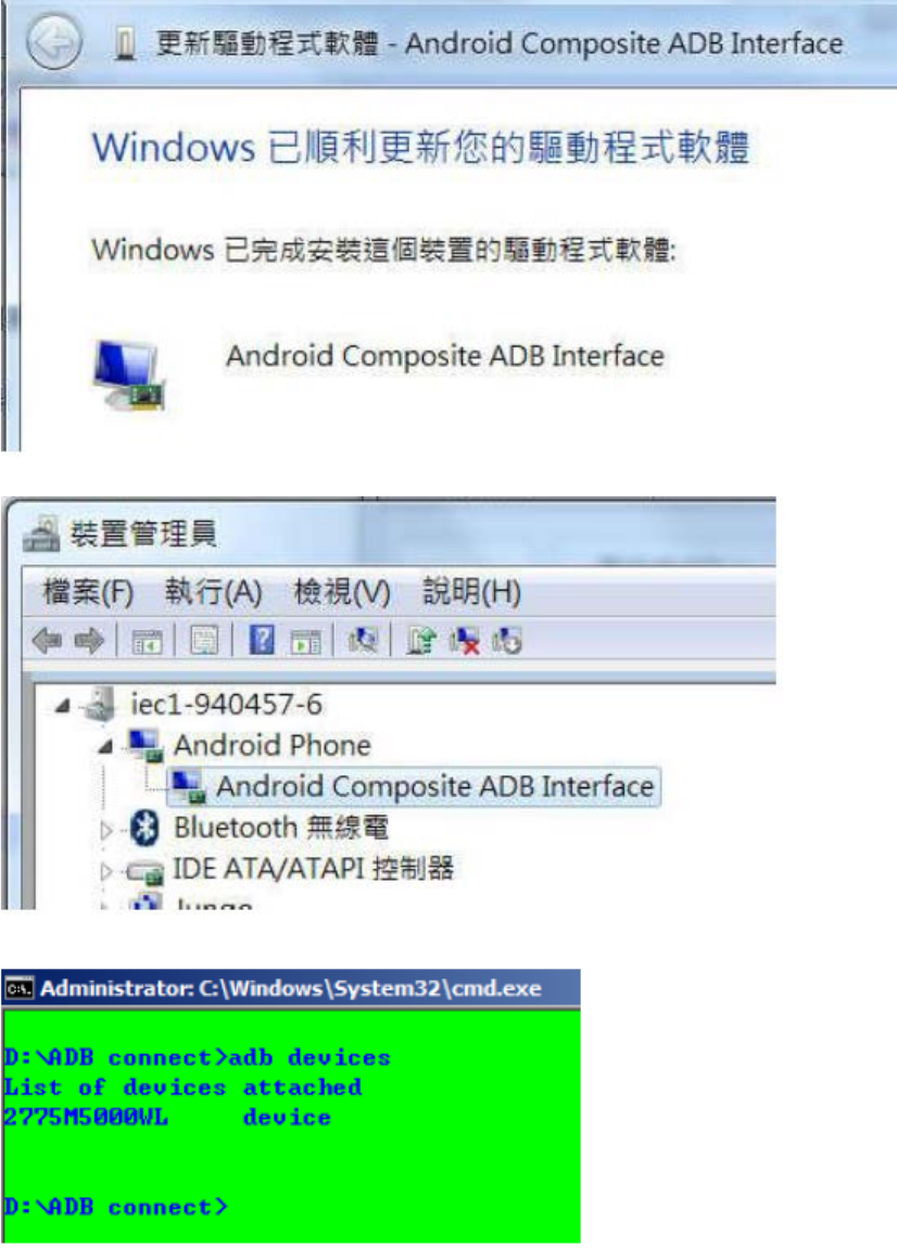
Check Device Manager
Open a window console and type “adb device” to confirm TREK-530 recognized.
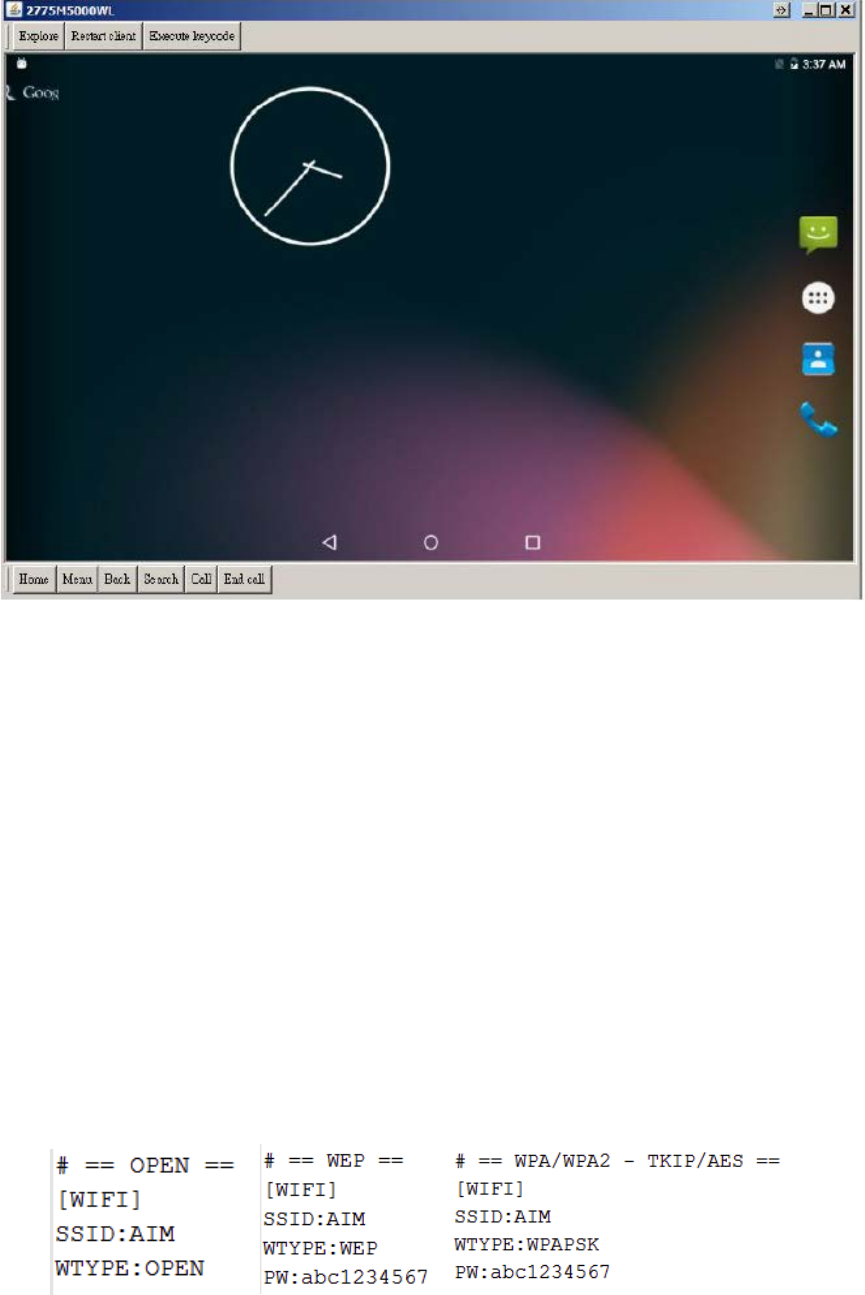
Establish screencast connection to TREK-530
Run androidscreencast.bat on PC to launch Android screencast. Then you can look the
desktop of TREK-530 remotely.
2.2.3.2 WiFi & Ethernet auto configure
Download a file “trek530_adv.cfg” from Advantech support website.
Change file setting in trek530_adv.cfg
Save trek530_adv.cfg in USB or SDCard storage
Plug storage into TREK530
WiFi Setting
– [WIFI] => Setting for WiFi
– SSID: => SSID name
– WTYPE: => Security Mode
OPEN
WEP
WPAPSK (Include WPA/WPA2 - AES/TKIP)
– PW: => Password (No Need if type is “OPEN”)
Ex:
Ethernet Setting
– [ETH] => Setting for Ethernet
– ETYPE: => Type of Ethernet
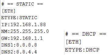
STATIC
DHCP (below setting can be ignore)
– IP: => STATIC IP
– NM: => NetMask
– GW: => GateWay
– DNS1: => DNS1(Option for static)
– DNS2: => DNS2(Option for static)
Ex:
Note :
Line ignore with “#” mark at first character
If there are same setting in file, value of last line will be used.
– Ex: Same SSID
[WIFI]
SSID:ABCD
SSID:5678 <- 5678 will be used
WTYPE:WEP
Setting also will be applied when boot up if storage is put in device before power on.
WiFi will be triggered to create connection with dedicated AP, but can’t guarantee the
connection will be successful. Connection can be created or not is depends on the signal
strength in current environment.

Chapter 3
4 I/O Connector
This chapter explains how to set up the
Computing Box hardware, including
instructions on setting.
Sections include:
I/O connectors pin assignment
3.1 I/O Connectors Pin Assignment
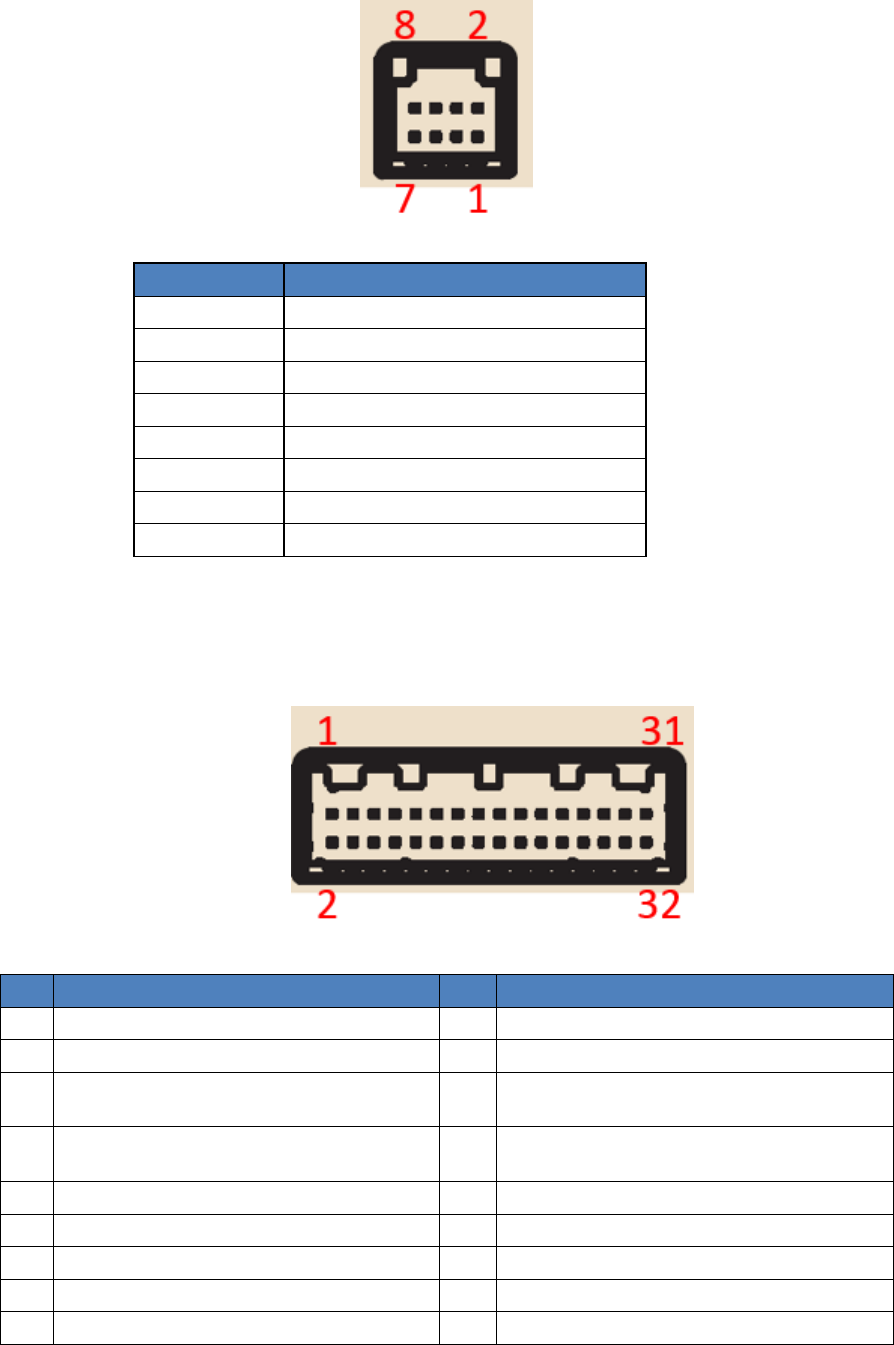
3.3.1 Power connector
Pin
Function
1 GND
2
GND
3
GND
4
GND
5 9~32V
6
9~32V
7
9~32V
8
IGNITION
3.3.2 High Density Connector
Pin
Function
Pin
Function
1
ISO Digital Input 1
17
USB D-
2
ISO Digital Input 2
18
GND
3 ISO Digital Input 3
19
RS-232_2 RXD
RS-485 Data +
4 ISO Digital Input 4
20
RS-232_2 DCD
RS-485 Data -
5
GNDof ISO DI/O
21
RS-232_2 CTS
6 ISO Digital Output 1
22
RS-232_2 RTS
7
ISO Digital Output 2
23
RS-232_2 TXD
8
J1708+(J+)
24
GND
9
GND(G)
25
RS-232_1 RTS
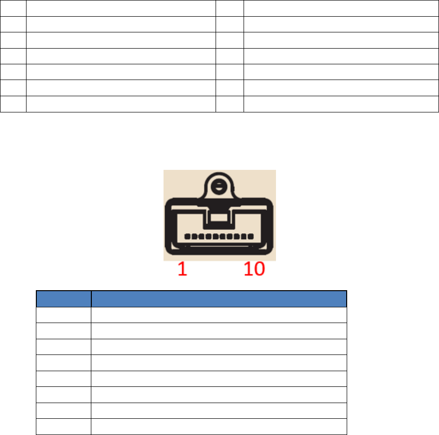
10
J1708-(J-)
26
RS-232_1 CTS
11 CAN H
27
RS-232_1 TXD
12
GND(G)
28
RS-232_1 RXD
13
CAN L
29
GND of Audio
14
USB VBUS
30
Line Out
15 GND
31
Line In
16
USB D+
32
MIC Input
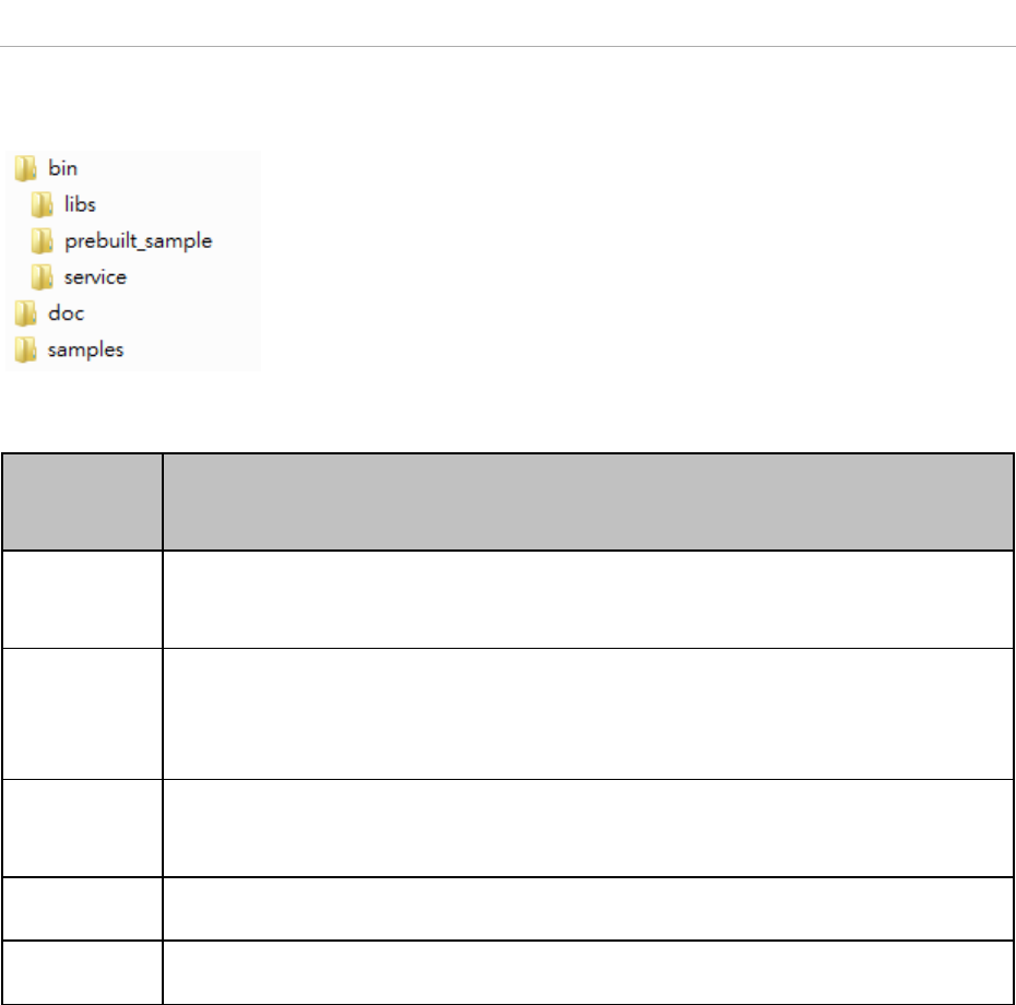
3.3.3 LAN Connector
Pin
Function
1 LAN_TX+
2
LAN_TX-
3
LAN_RX+
4
(Pair C+)
5 (Pair C-)
6
LAN_RX-
7
(Pair D+)
8
(Pair D-)

Chapter 4
6 Software Demo Utility
Setup
This chapter explains the soft-
ware demo utility for TREK-530
Sections include:
„
Introduction
„
How to Set up Demo Utility
1 MRM SDK Package Contents
The MRM SDK package contains the following contents:
The description of each of the folder at the top level is listed below:
Files/Directori
es
Description
bin/library/
The Java library and native library files.
These libraries should be imported in to your APP project.
bin/service/
The MRM service APK file.
The service APK file must be installed into your device before running your APP or
prebuilt sample APPs.
bin/prebuilt_sa
mple/
The prebuilt APK files of sample codes.
doc
The Documents.
samples
The sample code.
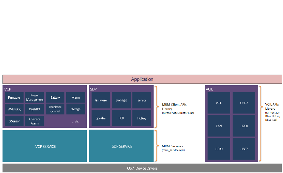
2 MRM SDK Overview
The MRM (Mobile Resource Management) SDK is a set of software libraries which provides APIs for
controlling various functions of the target device.
The following figure describes the software stack of MRM SDK:
MRM SDK is composed of the following function domains:
• IVCP (Intelligent Vehicle Co-Processor)
A VPM(Vehicle Power Management) MCU(Micro Controller Unit) is embedded in the device, which
controls the power status of device and peripheral devices such as G-Sensor and P-Sensors.
The IVCP function domain is designed in client-service architecture. The IVCP Service acts as a
proxy to access the VPM MCU and is able to serve multiple APP processes simultaneously. In your
APP, you can use the IVCP APIs exported in the MRM Client APIs Library to communicate with the
IVCP service.
IVCP Service Client API Modules:
o Firmware APIs - Get VPM MCU firmware version. Save/Load default settings
o Power Management APIs - VPM related functions. ex: boot control, Ignition control, event
delay adjustments, low battery protection and etc.
o Battery APIs - Backup battery related information and functions
o Alarm APIs - Internal RTC time setting and device alarm wakeup related functions.
o Watchdog APIs - Watch dog functions.
o Peripheral Control APIs - Power status management of peripheral devices.
o Storage APIs - Internal EEPROM storage access.
o G Sensor APIs - Access G sensor data. G sensor related settings.
o G Sensor Alarm APIs - G sensor device wakeup functions.
o P Sensor APIs - Access P sensor data.
• SDP (Smart Display Panel)
Depends on the specific device spec, the device may bundle with a smart display panel module.
The smart display panel module is embedded with a MCU to control functions of the module.
Similar with IVCP function domain, the SDP function domain is also designed in client-service
architecture. You can use the SDP APIs exported in the MRM Client APIs Library to communicate
with the SDP service.
SDP Service Client API Modules:
o Firmware APIs - Get SDP MCU firmware version. Save/Load default settings
o Backlight APIs - Configure brightness of smart display.
o Sensor APIs - Access sensor on smart display
o Hotkey APIs - hotkeys related settings.
o Speaker API - Speaker related settings
o USB API - USB port related settings
• VCIL (Vehicle Communication Interface Layer)
A VCIM(Vehicle Communication Interface Module) MCU is embedded in the device for controlling
the vehicle communication protocols (e.g. CAN, J1939, OBD2, J1708, J1587). For the performance
considerations, the VCIL function domain is designed in form of libraries, You can use the VCIL APIs
exported in the VCIL API Library to control the MCU directly. For VCIL does not has service layer,
the VCIL API Library does NOT support multi-process access.
VCIL API Modules:
o VCIL APIs - Get VCIL MCU firmware version. Physical port protocol settings.
o CAN APIs - Read / write data with CAN protocol.
o J1939 APIs - Read / write data with J1939 protocol.
o OBD2 APIs - Read / write data with OBD2 protocol.
o J1708 APIs - Read / write data with J1708 protocol.
o J1587 APIs - Read / write data with J1587 protocol.
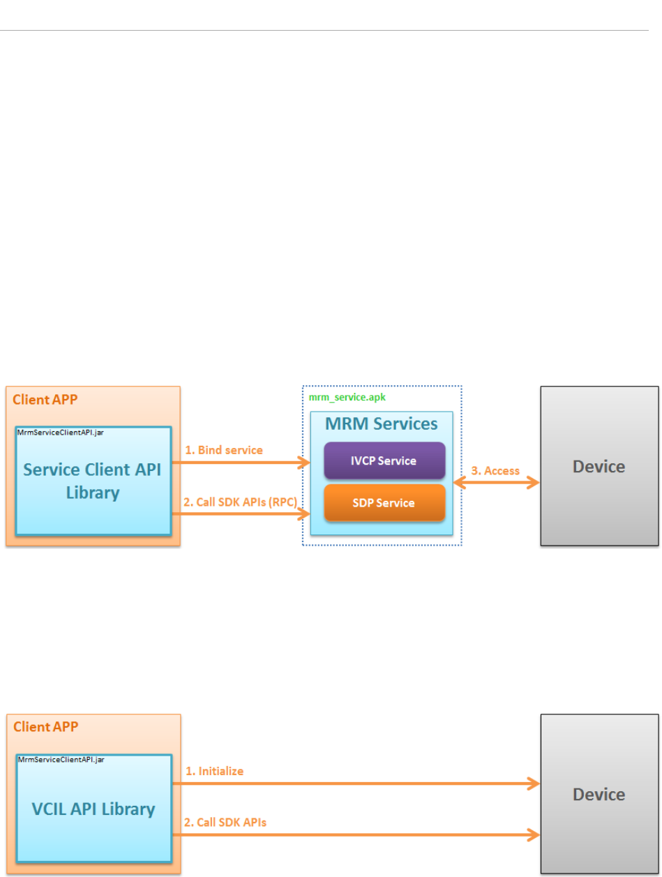
3 How MRM SDK Works
IVCP and SDP functions in the MRM SDK for Android is designed in client-service architecture.
To make your APP work with the MRM services to control the device you must first include the Service
Client API library into you APP project. Before calling APIs to control the device, you must first "bind"
you APP process to the MRM service processes. After binding is done, you can then call the IVCP, SDP
APIs to communicate with the services. The MRM services act as proxies for client APP to access the
hardware functions.
Due to the nature of client-service structure, the MRM SDK for Android supports multi-processes
access. It is available for the services to serve multiple application processes at the same time. The
hardware resources are managed by the services and the client application does not need to worry
about hardware resource occupation.
VCIL functions in the MRM SDK for Android is designed in form of libraries.
Before calling APIs to control the device, you must first call the initialization API to make the VCIM
MCU ready to work. After initialization is done, you can then call the VCIL APIs to do operations of
vehicle protocols.
4 Installation of the MRM SDK
You can install SDK(MRM Services) to your device by follow the steps below
1. Unzip the SDK package
Extract the SDK package zip file with password.
The password is same as the filename.
2. Install MRM Services (mrm_service.apk)
( NOTE: This step is only necessary for IVCP and SDP function. You can skip this step if you only
need VCIL functions )
Connect device to you computer with ADB.
Execute the script install_mrm_service.bat in [SDK_Pacakge]/bin/
The script will execute the following ADB command:
adb install -r .\mrm_service.apk
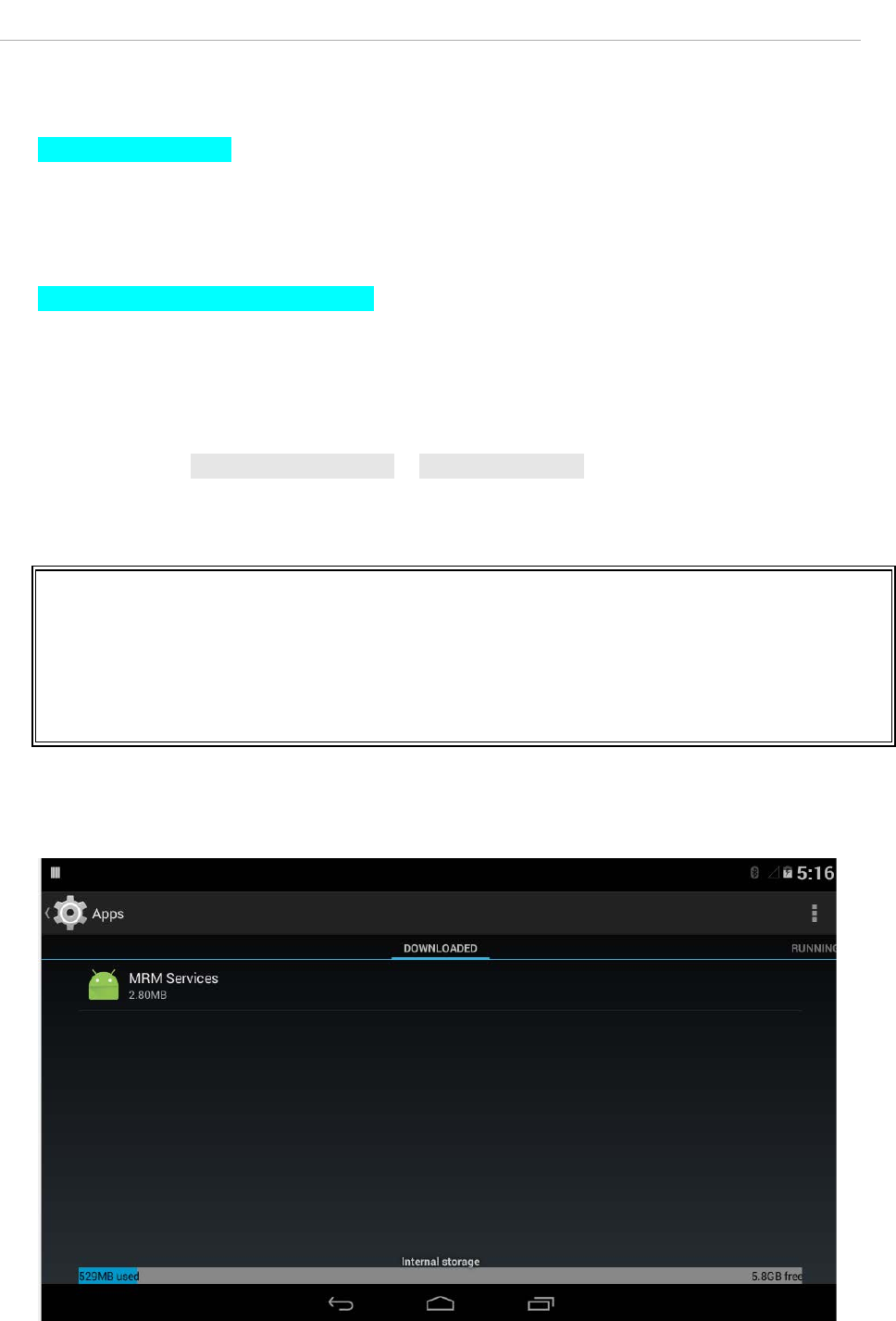
After installed, you will get the following package in your devices
There will also be an MRM Service Console APP named "MRM" in the APP list. This is a utility for
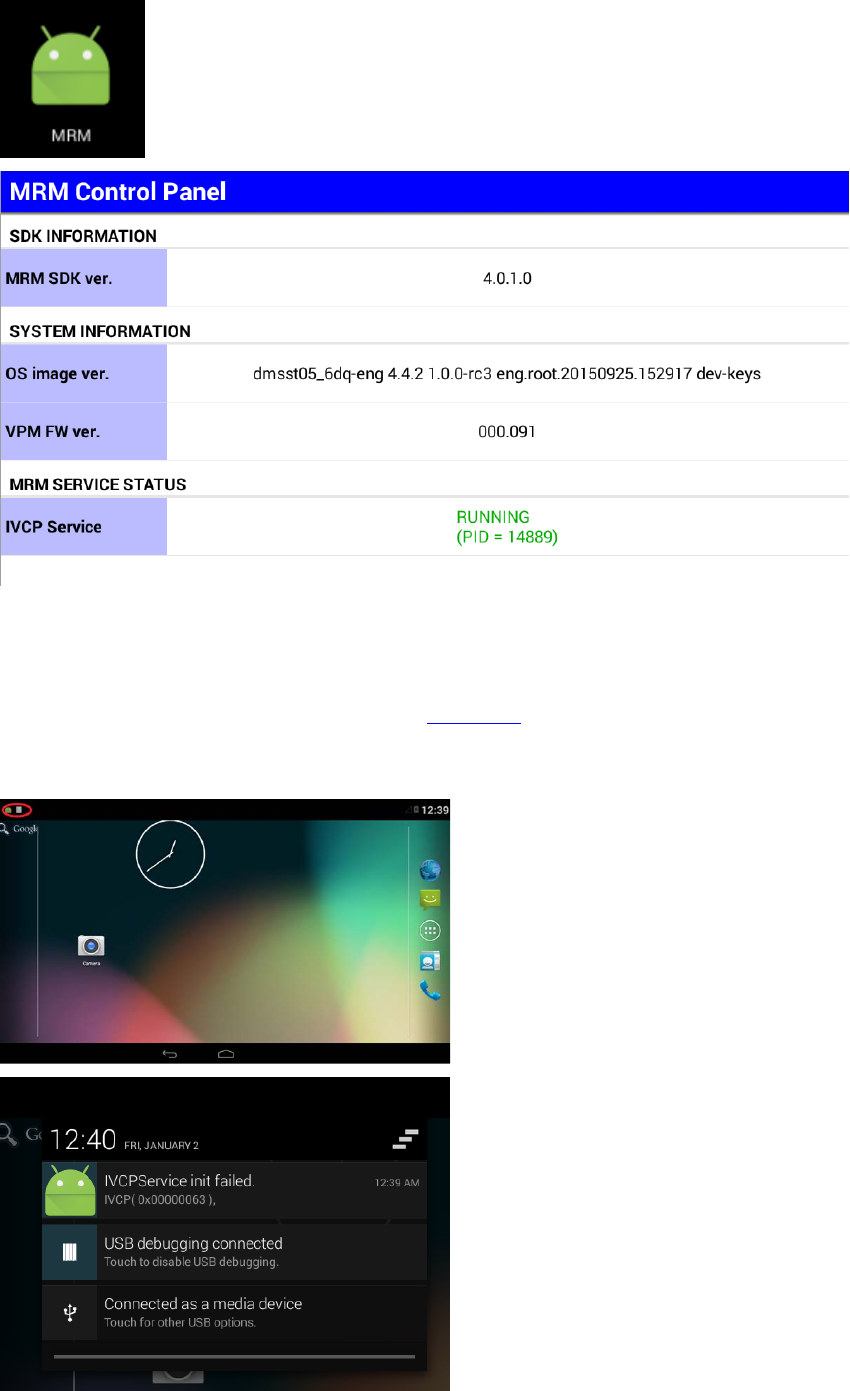
testing MRM Services and checking the basic information.
When MRM is launched, it will try to bind all MRM services. The MRM Services will be started and
initialize related hardware resources.
If initialization failed, you can get message with error code in the notification area (drag down
from left top of screen).
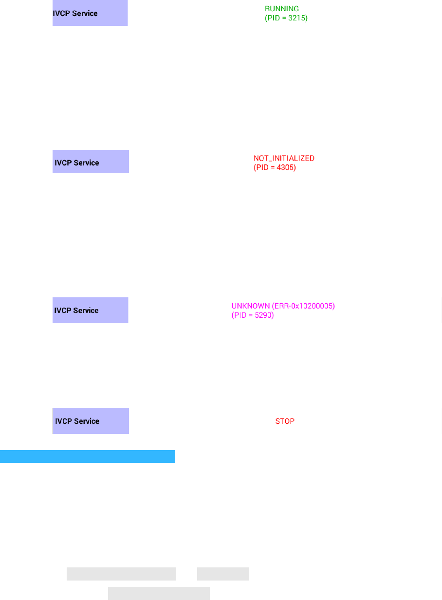
In the MRM, the service status will should be shown with the service process ID. The status will be
one of the followings:
o RUNNING
Service process is working correctly.
ex:
o NOT_INITIALIZED
Service process exists but the hardware resources can not be initialized. In this
status, the IVCP APIs can not work properly.
You can find the error code message in the notification area.
ex:
o UNKNOWN
Service process exists but the initialization status can not be confirmed.
The error code will be also shown. (For the definition of error codes, please refer
to the IVCP, VCIL, SDP User Manual)
ex:
o STOP
Service process does not exist.
ex:
3. Import MRM Service Client APIs Library
( NOTE: This step is only necessary for IVCP and SDP function. You can skip this step if you only
need VCIL functions )
To access MRM Service from your APP, you must import the MRM Service Client API lib into you
project.
Please find the MrmServiceClientAPI.jar and MrmDef.jar in the MRM SDK package. Copy the
libraries to the directory /[Module Name]/libs/ in you Android Studio project (the default
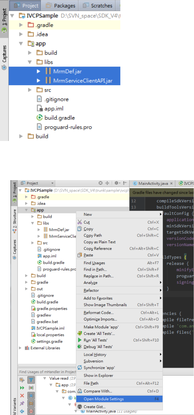
module name might be "app").
Then import the libraries by following the steps below:
o Right click on you APP module. Click "Open module settings"
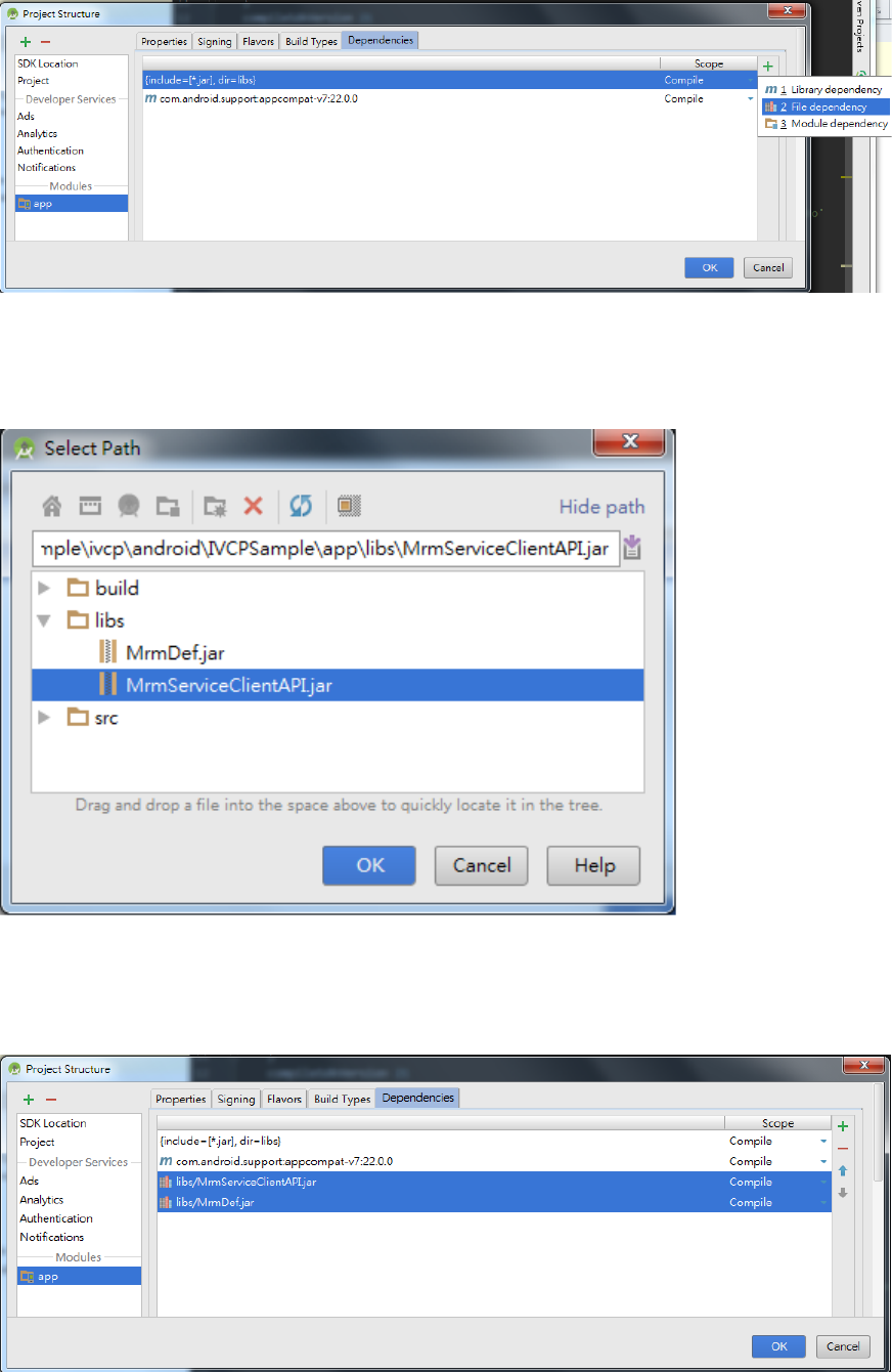
o Click the "Dependency" tab. Then click "+" -> "File dependency"
o Select the lib file.
o Repeat the above steps to add all libs and you will see all libs are added to the list.
4. Import VCIL APIs Library
( NOTE: This step is only necessary for VCIL functions )
To access VCIL functions from your APP, you must import the VCIL libraries into you project.
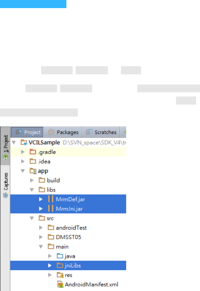
Please find the MrmJni.jar, MrmDef.jar and jniLibs/ folder in the MRM SDK package.
Copy the MrmJni.jar, MrmDef.jar to the directory /[Module Name]/libs/ in your Android Studio
project (the default module name might be "app") and copy the jniLibs/ folder to the directory
/[Module Name]/src/main/ .
Then import the Java libraries by following the steps below:
o Right click on you APP module. Click "Open module settings"
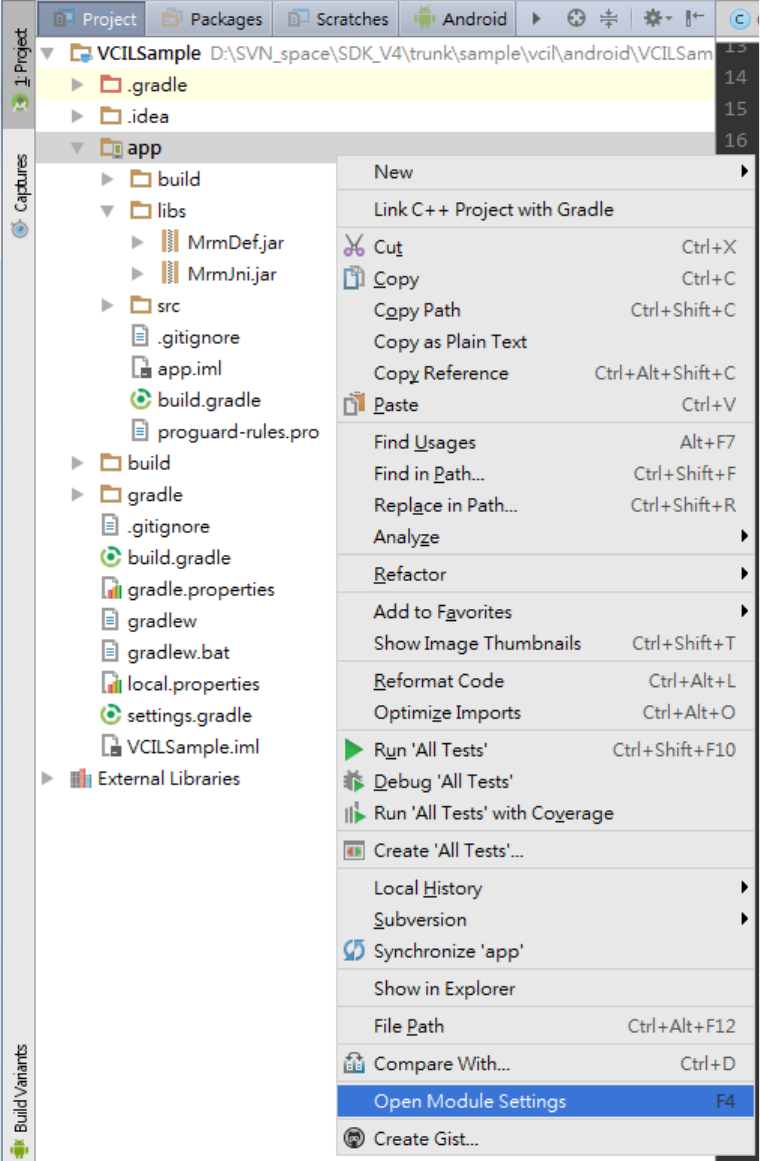
o Click the "Dependency" tab. Then click "+" -> "File dependency"
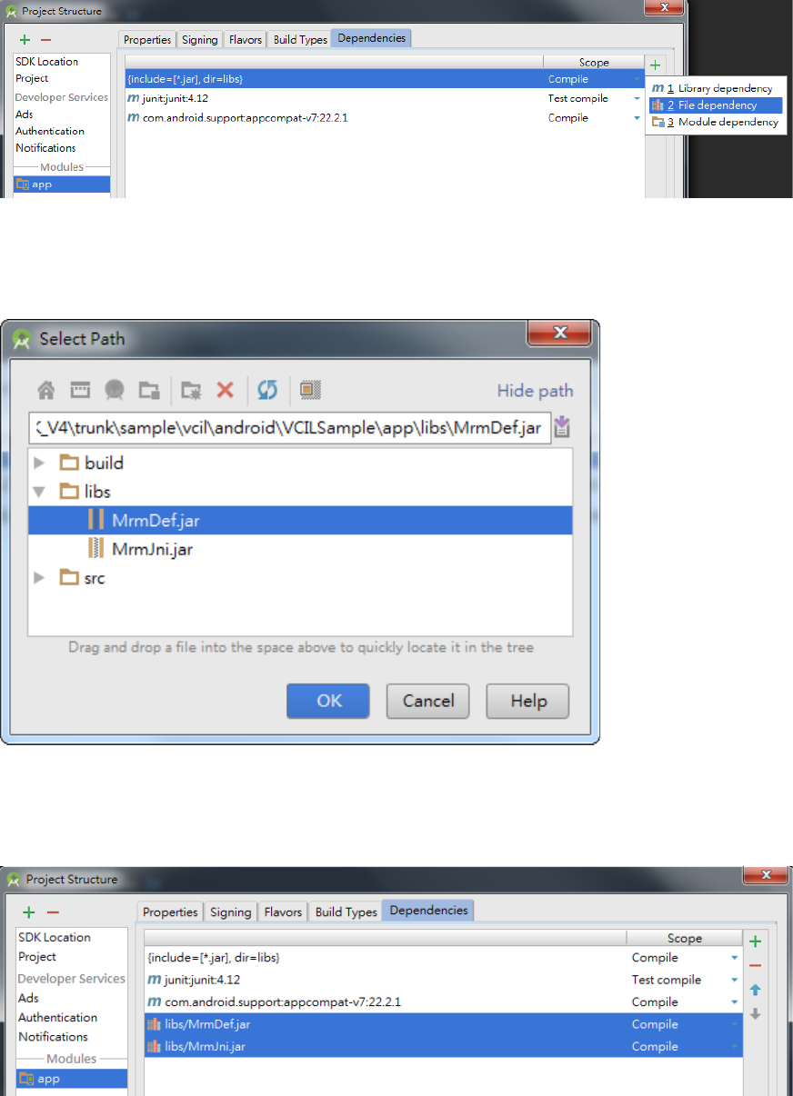
o Select the lib file.
o Repeat the above steps to add all libs and you will see all libs are added to the list.

5 Install Prebuilt Sample Apps
The prebuilt sample is placed in [SDK_Pacakge]/bin/samples/ .
Execute the script install_sample_apps.bat to install to your device.
The script will execute the following ADB command:
adb install -r .\IVCPSample.apk
adb install -r .\SDPSample.apk
adb install -r .\VCILSample.apk
Please note that you must install the MRM Services (mrm_service.apk) fist or the sample APPs will not
work.
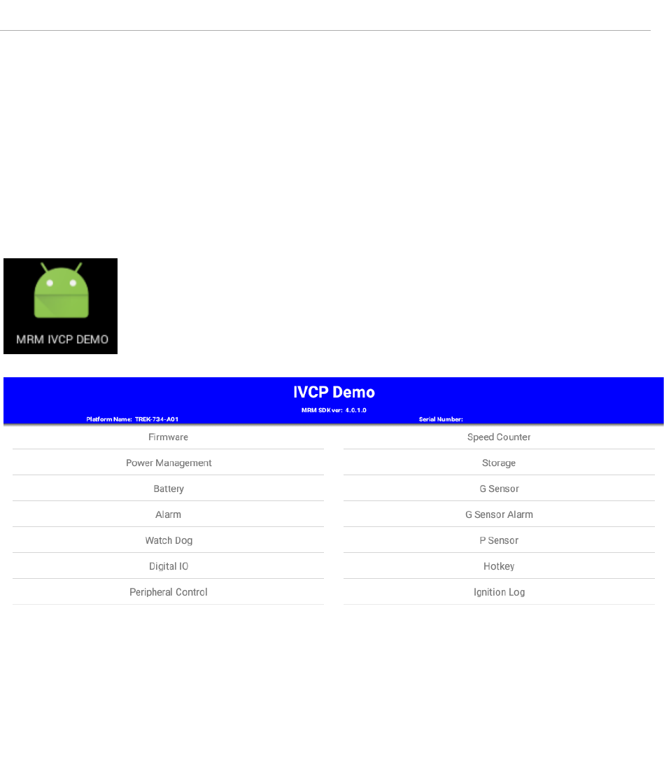
6 IVCP Demonstration
The IVCP sample APP (IVCPSample.apk) demonstrates the usage of IVCP APIs. You can tap on the items
in the list to start demo. The following sections show the usage guide line of basic items.
NOTE:
There might be some functions which are not supported on your device.
For the details of supported functions, please refer to the hardware spec.
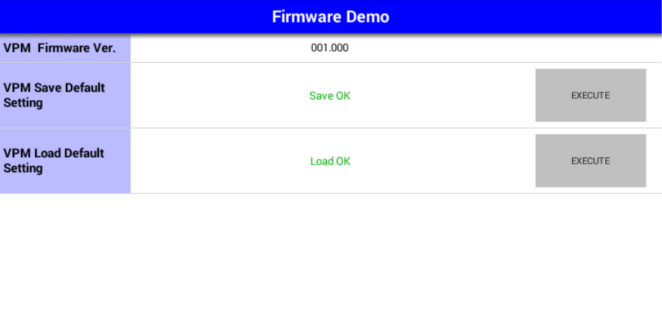
6.1 Firmware
This page demonstrates the Firmware APIs.
To save/load the default settings of VPM firmware, you can press the corresponding "EXECUTE"
button.
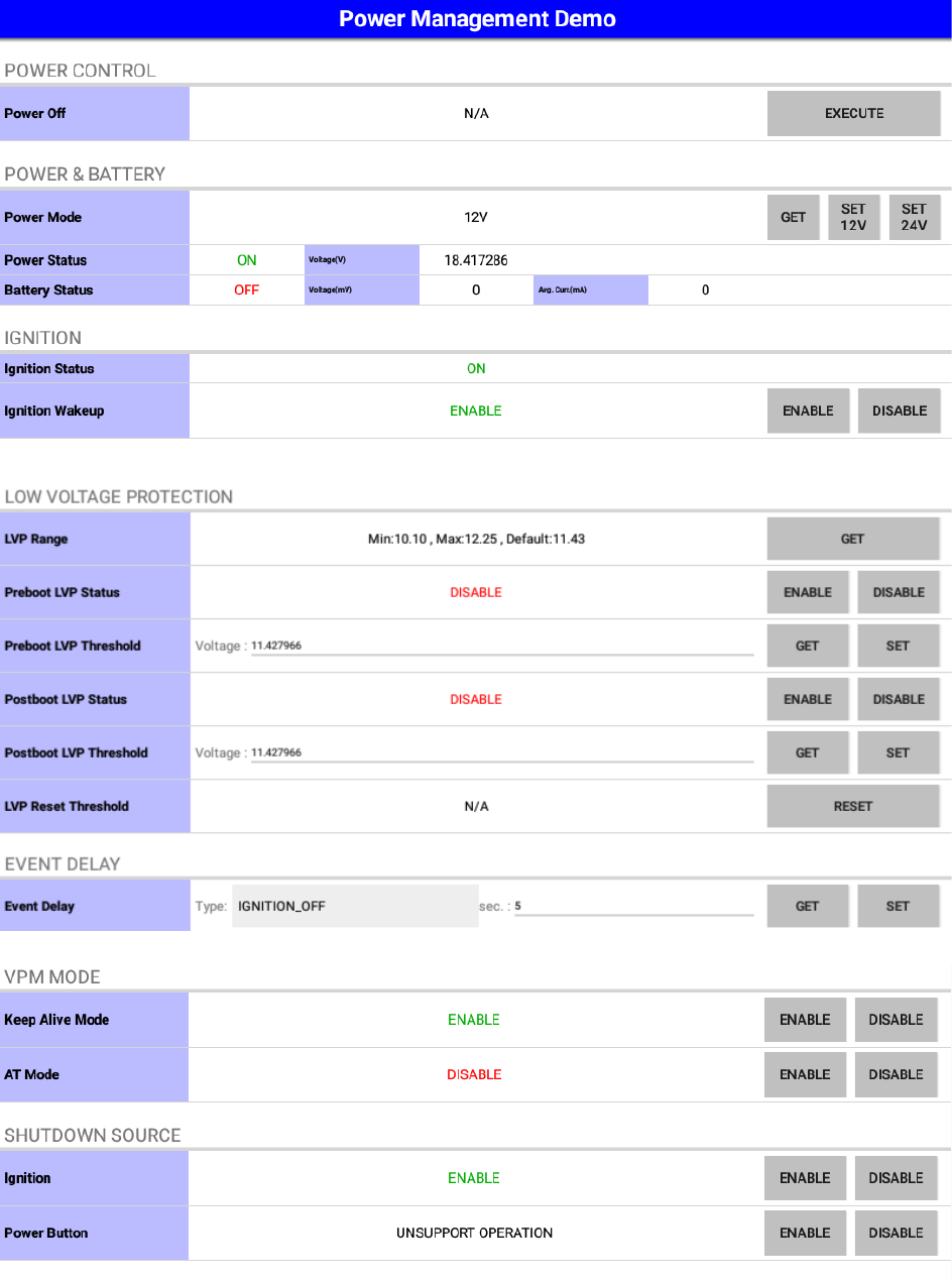
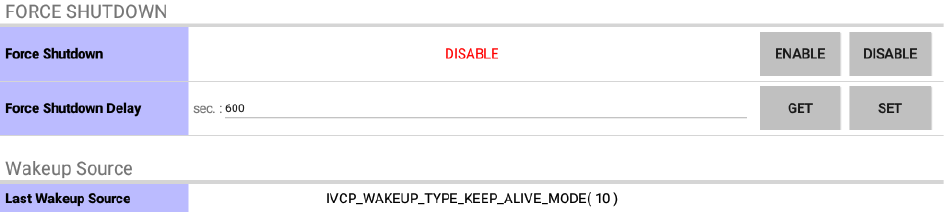
6.2 Power Management
This page demonstrates the Power Management APIs.
Each row shows demonstration different APIs. You can press the buttons at the right side to do
corresponding demo actions.
• Power Control
o VPM trigger power off event
• Power & Battery
o Get/Set power mode and show Power & Battery status
• Ignition
o Show ignition status and Control ignition wakeup.
• Low Voltage Protection
o Control preboot/postboot low voltage protection and get/set preboot or postboot LVP
threshold. It also can reset low voltage protection to default value and get default range.
NOTE:
The Postboot LVP Threshold voltage must less than or equal to Preboot LVP Threshold
voltage.
• Event Delay
o Low Voltage Event Delay:
The delay time before VPM trigger a power off event (i.e. power button press).
o Low Voltage Event Hard Delay:
The delay time counted down after a power off event is triggered. VPM will force power
off the machine if the hard delay time is counted down to zero.
o Ignition Event On Delay:
The delay time before VPM trigger an power on event (power on the machine).
o Ignition Event Off Delay:
The delay time before VPM trigger an power off event (i.e. power button/Ignition off
press).
o Ignition Event Hard Off Delay:
The delay time counted after an power off event is triggered. VPM will force power off the
machine if the hard delay time is counted down to zero.
• VPM Mode
o Control Keep Alive and AT mode.
• Force Shutdown
o Control force shutdown and get/set force shutdown delay.
• Wakeup Source
o Show last wakeup source.
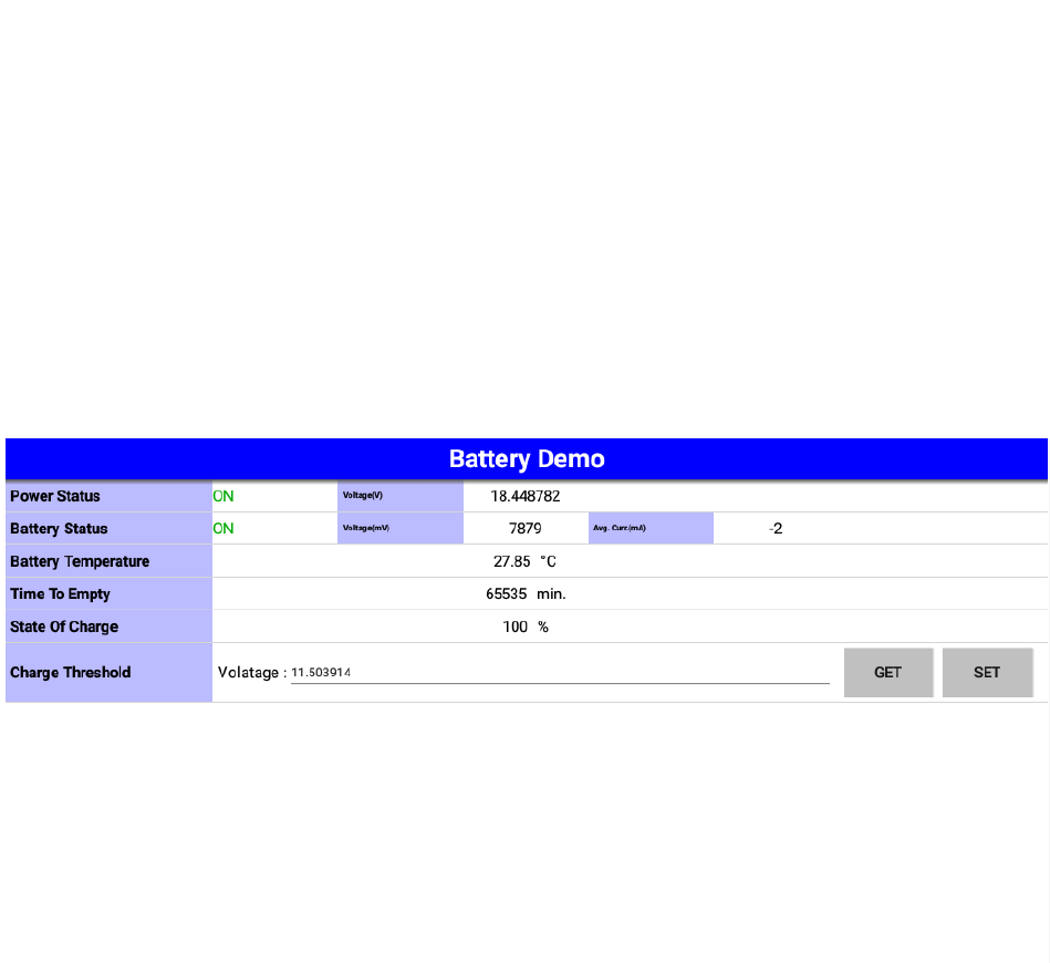
6.3 Battery
This page demonstrates the Battery APIs.
Each row shows demonstration different APIs. You can press the buttons at the right side to do
corresponding demo actions.
You can adjust the battery setting of VPM in this page.

6.4 Alarm
This page demonstrates the Alarm APIs.
Each row shows demonstration different APIs. You can press the buttons at the right side to do
corresponding demo actions.
You can adjust the RTC time and device alarm wakeup setting of VPM in this page.
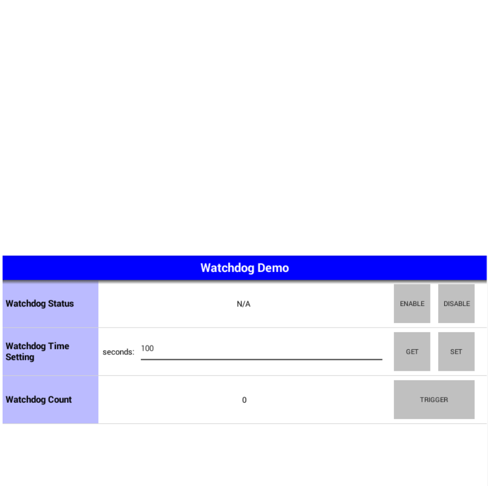
6.5 Watchdog
This page demonstrates the Watchdog APIs.
Each row shows demonstration different APIs. You can press the buttons at the right side to do
corresponding demo actions.
When the "enable" is pressed, the watch dog will start count down and the count will be updated to
the "watchdog count" row.
You can press "trigger" button to reset the count or press "disable" button to stop watch dog.
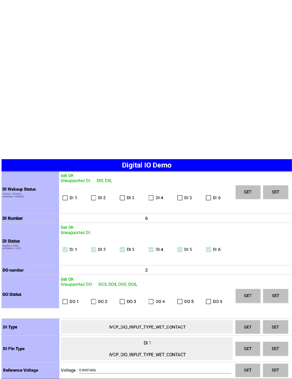
6.6 Digital IO
This page demonstrates the Digital IO APIs.
Each row shows demonstration different APIs. You can press the buttons at the right side to do
corresponding demo actions.
In the row of "DI Status", the status of each DI pins will be updated periodically to corresponding check
boxes.
In the row of "DI Type", you can adjust the wet/dry contact for all DI pin. In the row of "DI Pin Type",
you can adjust the wet/dry contact for specify DI pin.
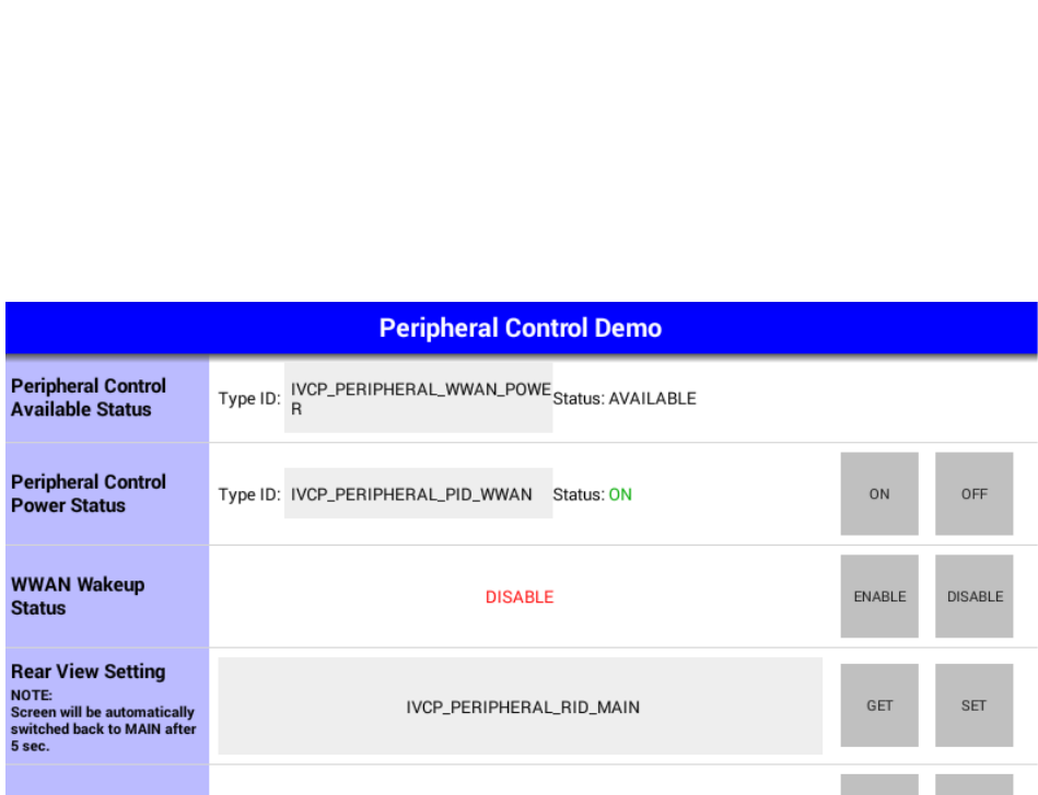
6.7 Peripheral Control
This page demonstrates the Peripheral Control APIs.
Each row shows demonstration different APIs. You can press the buttons at the right side to do
corresponding demo actions.
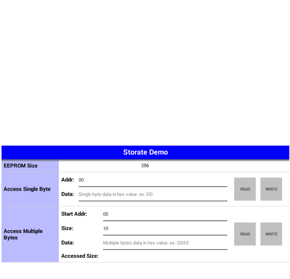
6.8 Storage
This page demonstrates the Storage APIs.
Each row shows demonstration different APIs. You can press the buttons at the right side to do
corresponding demo actions.
The "data" column in each row is represented in HEX string. To write data, you should input the data in
HEX string format. For example, to write 2 bytes data - "DD" and "EE" - to the storage, you must input
"DDEE" to the data column.
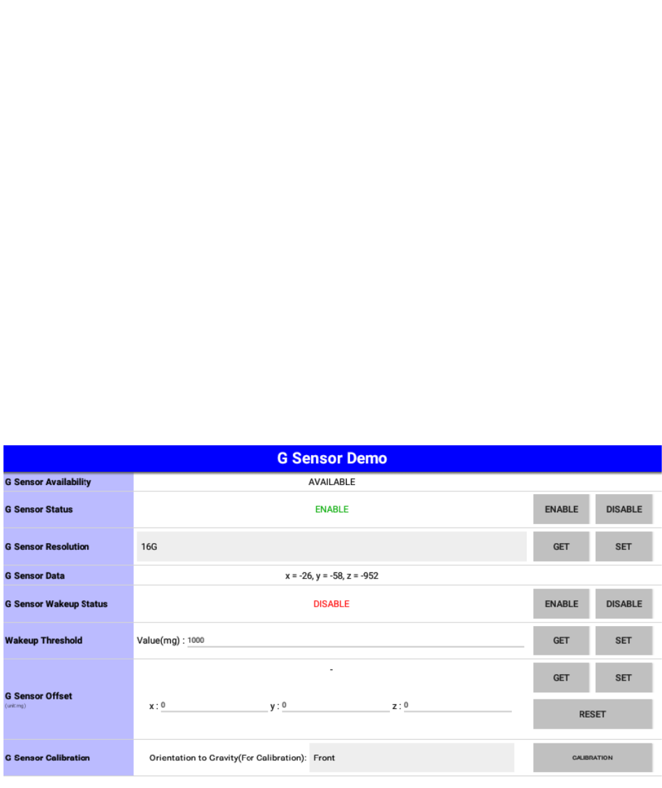
6.9 G Sensor
This page demonstrates the G Sensor APIs.
Each row shows demonstration different APIs. You can press the buttons at the right side to do
corresponding demo actions.
The G sensor status is updated periodically in the G sensor data row.
In the row of "G Sensor Offset", you can get/set the G Sensor Offset. Click "Reset" button to reset G
Sensor Offset to default (x=0,y=0,z=0).
In the row of "G Sensor Calibration", the G sensor calibration should be decided by orientation to
gravity. In the front, G sensor data will be x=0, y=0, z=1000 (mg). In the back, G sensor data will be x=0,
y=0 ,z=-1000(mg)
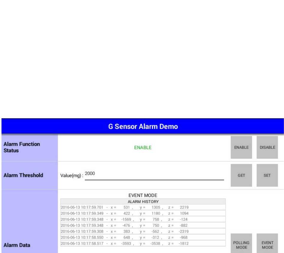
6.10 G Sensor Alarm
This page demonstrates the G Sensor Alarm APIs.
Each row shows demonstration different APIs. You can press the buttons at the right side to do
corresponding demo actions.
When G sensor alarm is enabled. The G sensor alarm data will be updated to the row "alarm data"
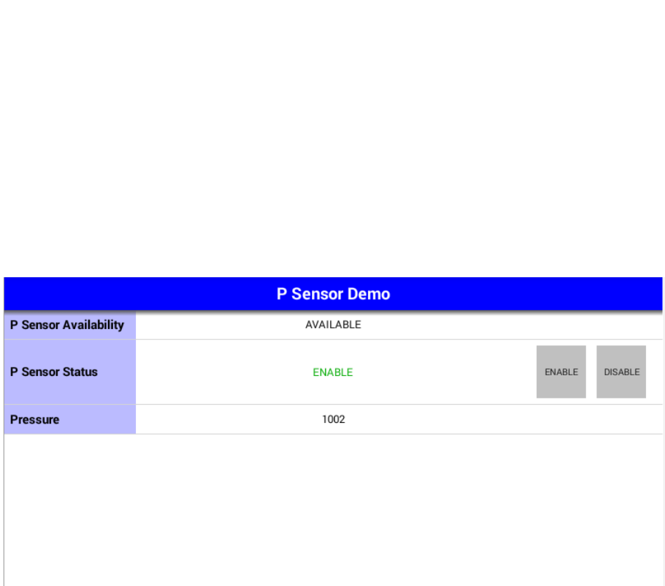
6.11 P Sensor
This page demonstrates the P Sensor APIs.
Each row shows demonstration different APIs. You can press the buttons at the right side to do
corresponding demo actions.
The P sensor status is updated periodically in the pressure row.
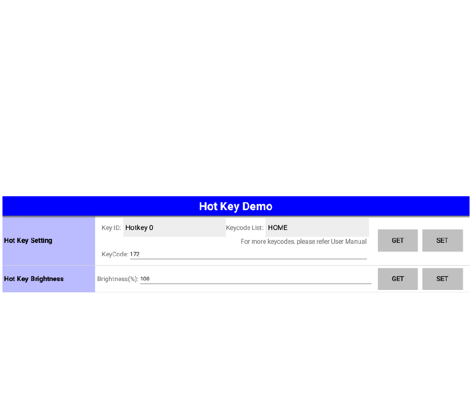
6.12 Hotkey
This page demonstrates the Hotkey APIs.
In the "Hoy Key Setting" row, you can set the keycode of corresponding function key on the device.
The keycode list will show the common keycode for easy setting.
In the "Hoy Key Brightness" row, you can set the brightness of LED back light of the function keys.
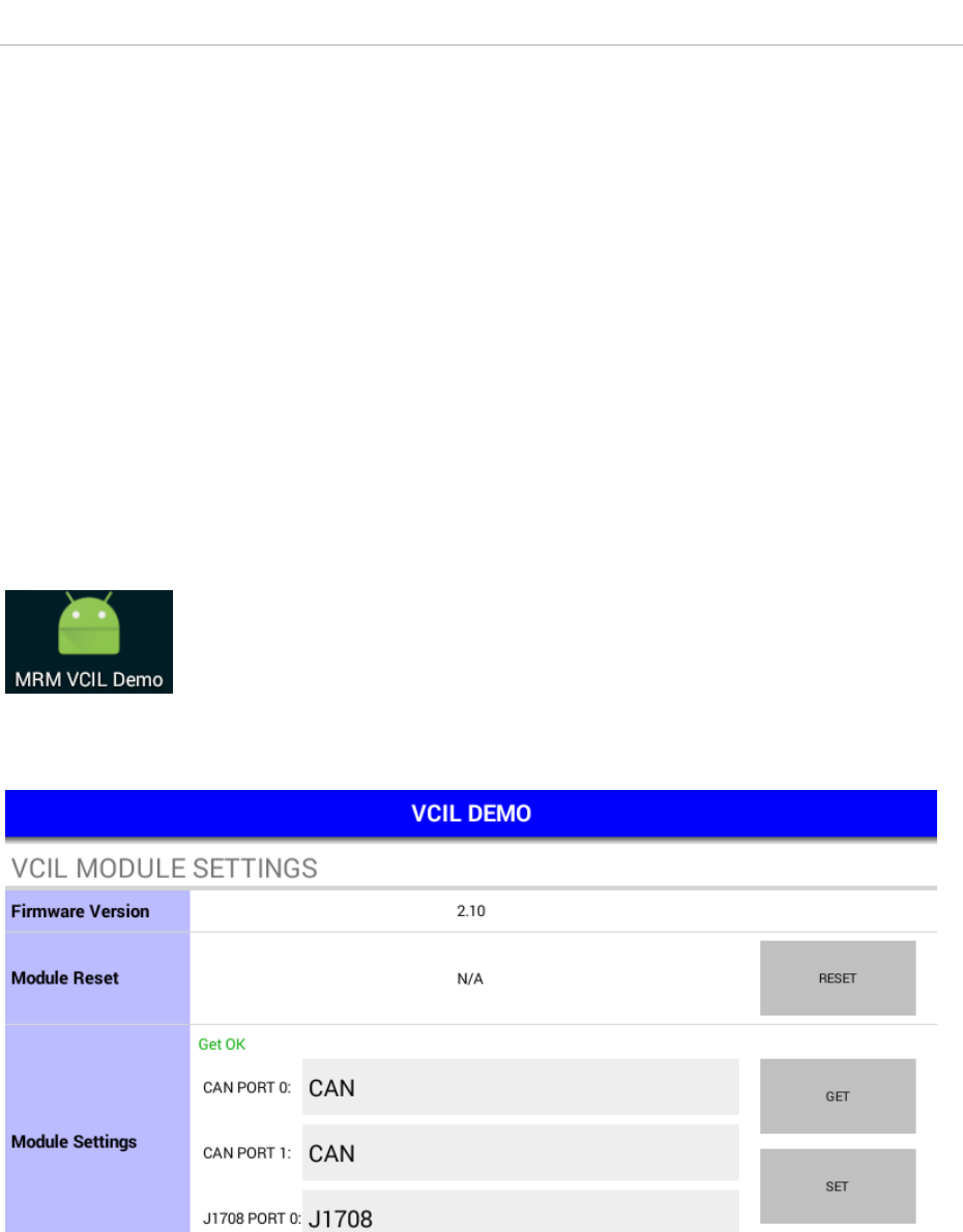
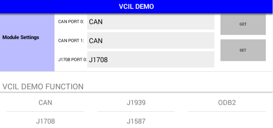
7 VCIL Demonstration
The VCIL sample APP (VCILSample.apk) demonstrates the usage of VCIL APIs.
In the entry page, you should first set the protocol for each physical port properly in the "module
settings" before you start other VCIL demo. Then, you can scroll to the bottom of the page and tap on
the items in the VCIL demo function list to execute the demos. The following sections show the usage
guide line of each items.
NOTE:
There might be some functions which are not supported on your device.
For the details of supported functions, please refer to the hardware spec.

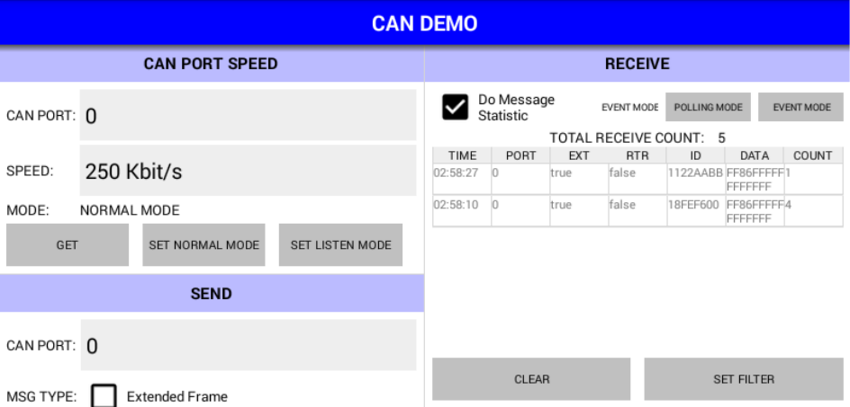
7.1 CAN
This page demonstrates the CAN APIs.
There are two scrolling areas in this page. The left side contains the demo of CAN port speed setting,
CAN message sending, and CAN port error status getting. The right side contains the demo of CAN
message receiving.
• CAN Port Speed Setting
In the "CAN PORT SPEED" area, you can set the bit rate for each CAN port.
Please note that you should also configure the bit rate for CAN port before you start J1939 and
OBD2 demo page.
The CAN, J1939, OBD2 demo may not be operational.
• CAN Message Sending
In the "SEND" area, you can set the contents of a CAN message and press "SEND" button to send
the message to CAN bus.
• CAN Port Error Status Getting
In the "CAN PORT ERROR STATUS" area, you can press "GET" button to get the error status of
specific CAN port.
• CAN Message Receiving
In the "RECEIVE" area, all received CAN messages will be categorized and shown in the list view.
The messages from the same CAN port with same CAN message ID will be updated to the same
row in the list view and the "COUNT" column will increase.
You can press the "SET FILTER" button to enter the CAN Filter demo page.
NOTE:
1. You must properly set the protocol in the entry page or the demo will not be operational.
2. You must set the CAN port speed properly or the sending and receiving function in CAN, J1939,
OBD2 demo page will not be operational.
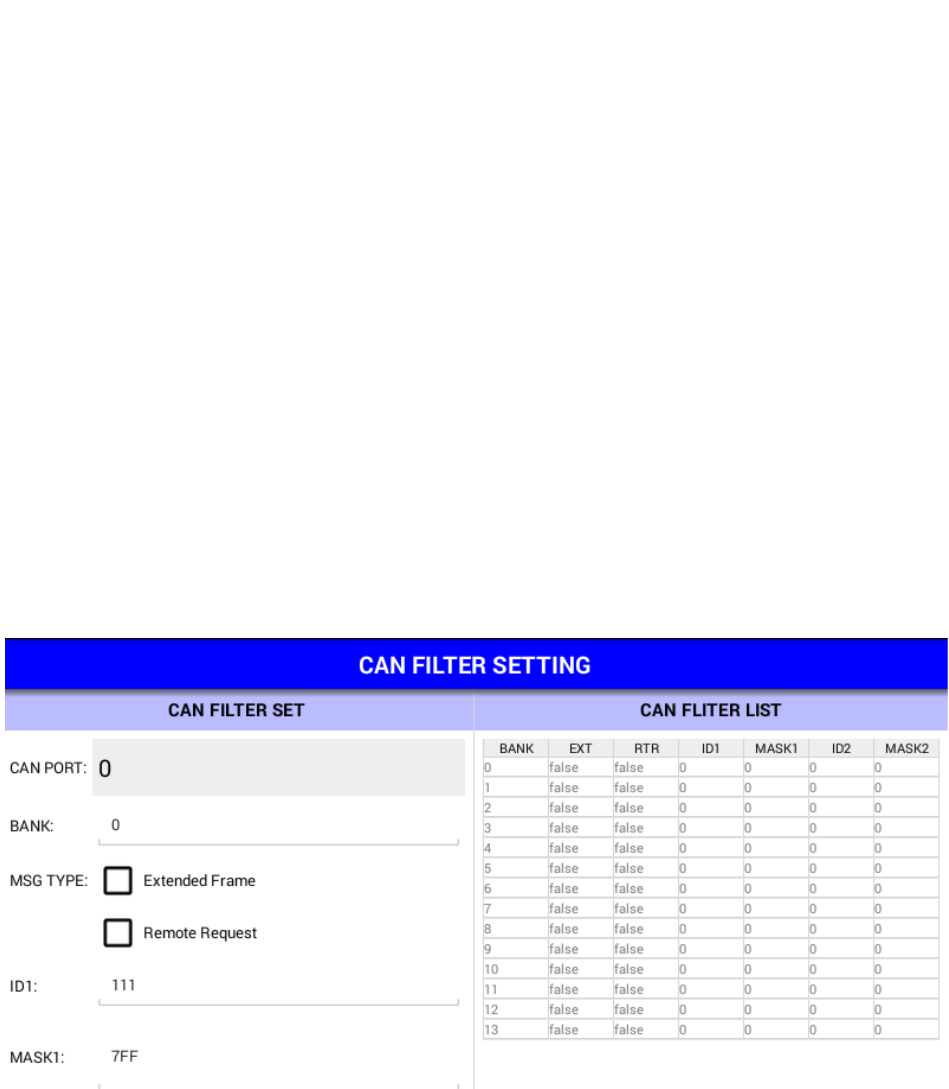
7.2 CAN Filter
This page demonstrates the CAN APIs related to CAN message filter.
There are two scrolling areas in this page. The left side contains the demo of CAN message filter
settings. The right side shows the filter of specific CAN port.
In the left side you can specify a filter (CAN ID) of specific CAN port and press "SET" button to apply it
or "REMOVE" to remove the filter. To show the filters applied on specific CAN port, you can choose the
CAN port ID and press the "GET" button and all filters will be shown to the right side.
In the right side, you can tap on the row in the list view to load the filter settings to the columns in left
side.

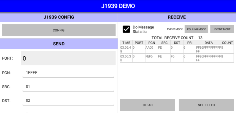
7.3 J1939
This page demonstrates the J1939 APIs.
There are two scrolling areas in this page. The left side contains the demo of J1939 config, and J1939
message sending. The right side contains the demo of J1939 message receiving.
• J1939 Config
Press the "CONFIG" button to enter the J1939 config page. You can configure the address and
J1939 NAME in the page.
• J1939 Message Sending
In the "SEND" area, you can set the contents of a J1939 message and press "SEND" button to send
the message to CAN bus.
• J1939 Message Receiving
In the "RECEIVE" area, all received J1939 messages will be categorized and shown in the list view.
The messages from the same CAN port with same PGN will be updated to the same row in the list
view and the "COUNT" column will increase.
You can press the "SET FILTER" button to enter the J1939 Filter demo page.
NOTE:
1. You must properly set the protocol in the entry page or the demo will not be operational.
2. You must set the CAN port speed properly or the sending and receiving function in CAN, J1939,
OBD2 demo page will not be operational.
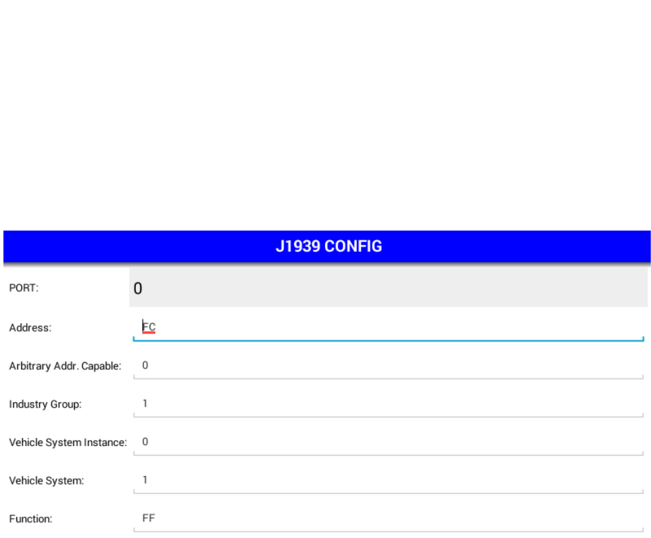
7.4 J1939 Config
This page demonstrates the J1939 APIs related to J1939 configuration.
You can set/get the address and J1939 NAME in this page. Please refer to SAE J1939-81 for the
definitions of J1939 NAME.
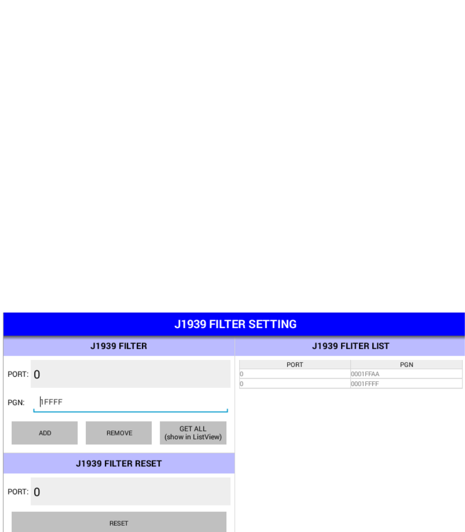
7.5 J1939 Filter
This page demonstrates the J1939 APIs related to J1939 message filter.
There are two scrolling areas in this page. The left side contains the demo of J1939 message filter
settings. The right side shows the filter of specific J1939 port.
In the left side you can specify a filter (PGN) of specific CAN port and press "SET" button to apply it or
"REMOVE" to remove the filter. To show the filters applied on specific CAN port, you can choose the
CAN port ID and press the "GET" button and all filters will be shown to the right side.
In the right side, you can tap on the row in the list view to load the filter settings to the columns in left
side.

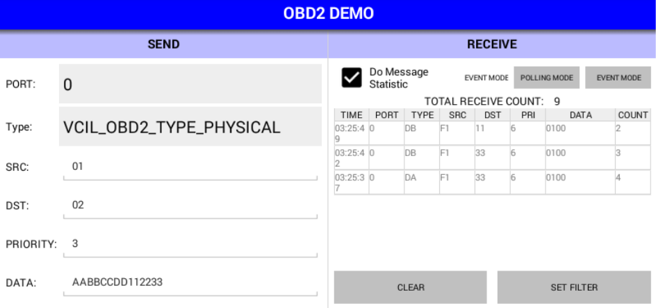
7.6 OBD2
This page demonstrates the OBD2 APIs.
There are two scrolling areas in this page. The left side contains the demo of CAN port speed setting,
OBD2 message sending. The right side contains the demo of OBD2 message receiving.
• OBD2 Message Sending
In the "SEND" area, you can set the contents of a OBD2 message and press "SEND" button to send
the message to CAN bus.
• OBD2 Message Receiving
In the "RECEIVE" area, all received OBD2 messages will be categorized and shown in the list view.
The messages from the same CAN port with same message type, source address and destination
address will be updated to the same row in the list view and the "COUNT" column will increase.
You can press the "SET FILTER" button to enter the OBD2 Filter demo page.
NOTE:
1. You must properly set the protocol in the entry page or the demo will not be operational.
2. You must set the CAN port speed properly or the sending and receiving function in CAN, J1939,
OBD2 demo page will not be operational.
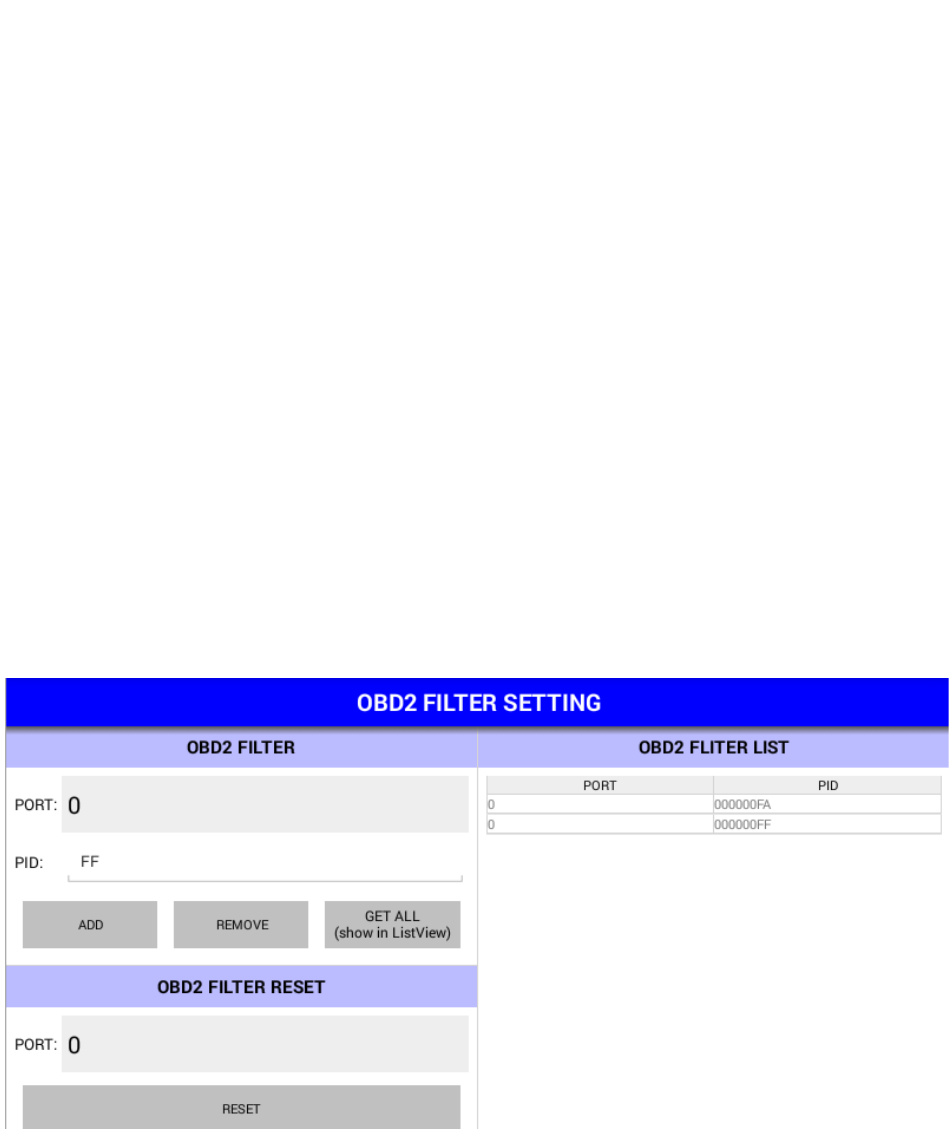
7.7 OBD2 Filter
This page demonstrates the OBD2 APIs related to OBD2 message filter.
There are two scrolling areas in this page. The left side contains the demo of OBD2 message filter
settings. The right side shows the filter of specific CAN port.
In the left side you can specify a filter (PID, please refer to ISO 15031-5) of specific CAN port and press
"SET" button to apply it or "REMOVE" to remove the filter. To show the filters applied on specific CAN
port, you can choose the CAN port ID and press the "GET" button and all filters will be shown to the
right side.
In the right side, you can tap on the row in the list view to load the filter settings to the columns in left
side.
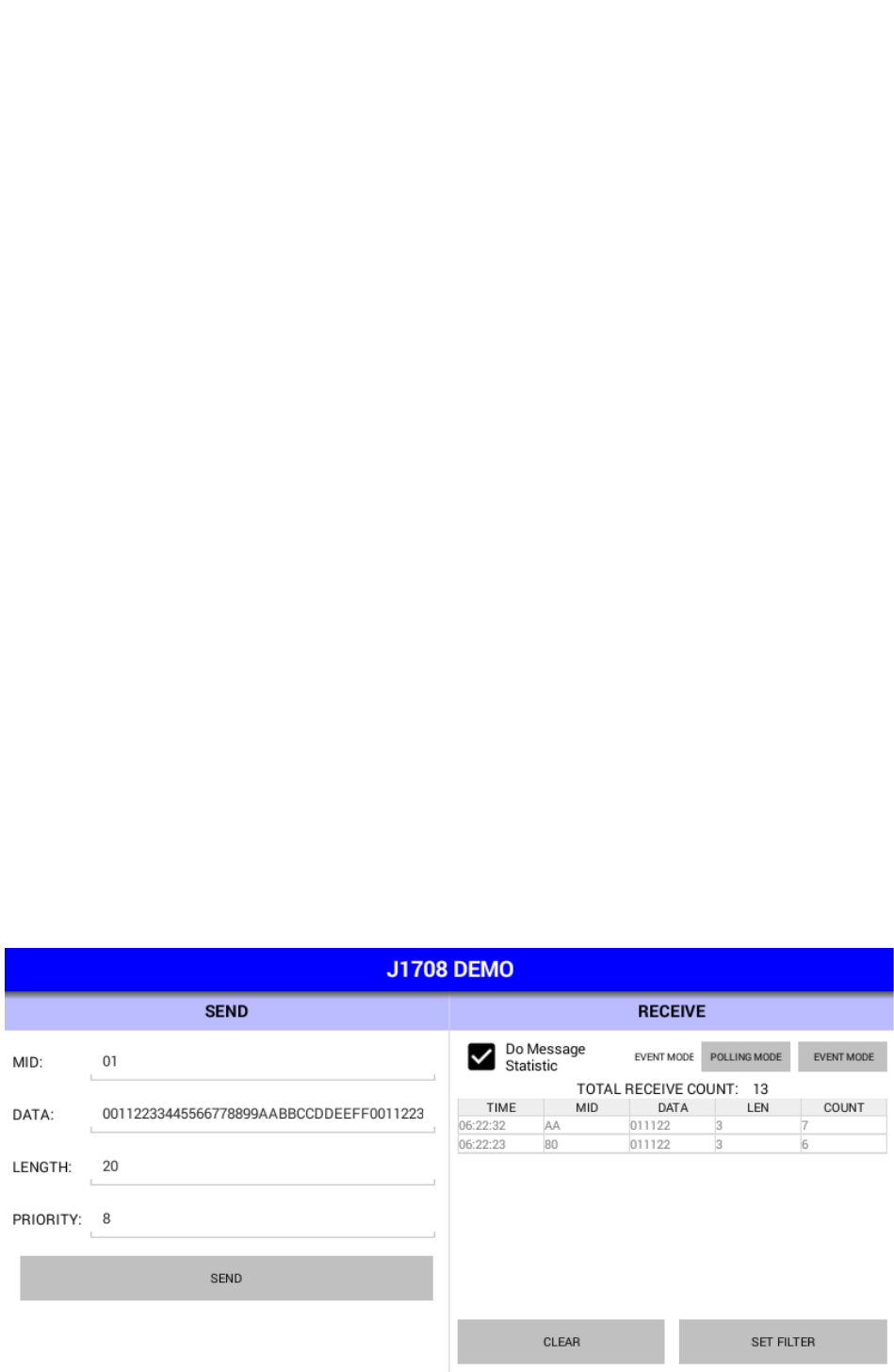
7.8 J1708
This page demonstrates the J1708 APIs.
There are two scrolling areas in this page. The left side contains the demo of J1708 message sending.
The right side contains the demo of J1708 message receiving.
• J1708 Message Sending
In the "SEND" area, you can set the contents of a J1708 message and press "SEND" button to send
the message to J1708 bus.
• J1708 Message Receiving
In the "RECEIVE" area, all received J1708 messages will be categorized and shown in the list view.
The messages with same MID will be updated to the same row in the list view and the "COUNT"
column will increase.
You can press the "SET FILTER" button to enter the J1708 Filter demo page.
NOTE:
1. You must properly set the protocol in the entry page or the demo will not be operational.
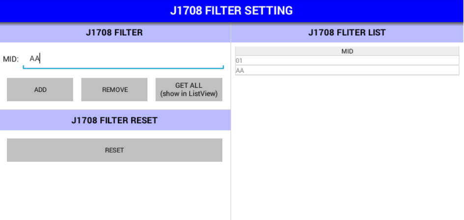
7.9 J1708 Filter
This page demonstrates the J1708 APIs related to J1708 message filter.
There are two scrolling areas in this page. The left side contains the demo of J1708 message filter
settings. The right side shows the filter of the J1708 port.
In the left side you can specify a filter (MID) and press "SET" button to apply it or "REMOVE" to remove
the filter. To show the filters applied on J1708 port, you can press the "GET" button and all filters will
be shown to the right side.
In the right side, you can tap on the row in the list view to load the filter settings to the columns in left
side.
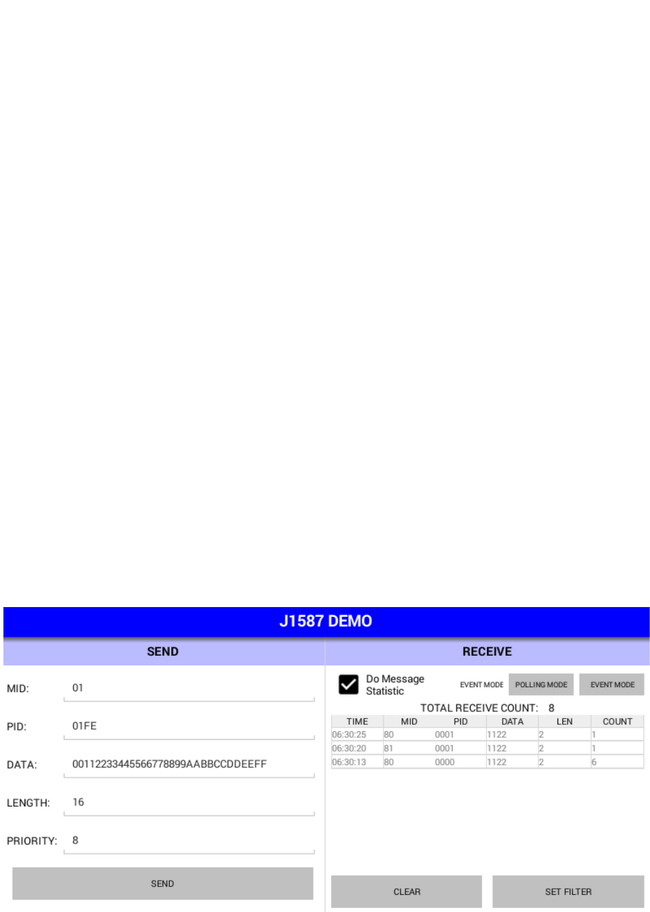
7.10 J1587
This page demonstrates the J1587 APIs.
There are two scrolling areas in this page. The left side contains the demo of J1587 message sending.
The right side contains the demo of J1587 message receiving.
• J1587 Message Sending
In the "SEND" area, you can set the contents of a J1587 message and press "SEND" button to send
the message to J1587 bus.
• J1587 Message Receiving
In the "RECEIVE" area, all received J1587 messages will be categorized and shown in the list view.
The messages with same MID will be updated to the same row in the list view and the "COUNT"
column will increase.
You can press the "SET FILTER" button to enter the J1708 Filter demo page.
NOTE:
1. You must properly set the protocol in the entry page or the demo will not be operational.
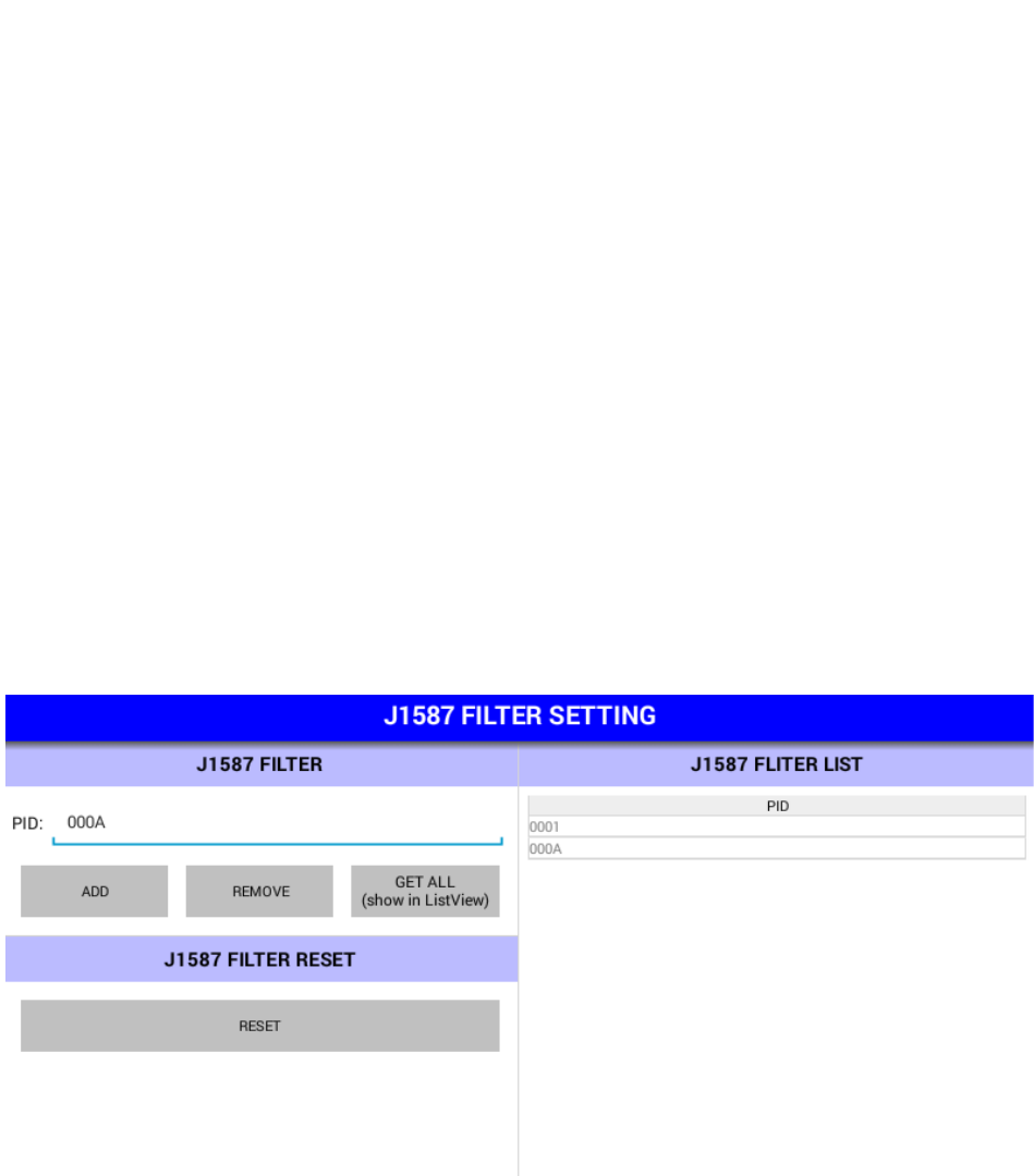
7.11 J1587 Filter
This page demonstrates the J1587 APIs related to J1587 message filter.
There are two scrolling areas in this page. The left side contains the demo of J1587 message filter
settings. The right side shows the filter of the J1587 port.
In the left side you can specify a filter (PID) and press "SET" button to apply it or "REMOVE" to remove
the filter. To show the filters applied on J1708 port, you can press the "GET" button and all filters will
be shown to the right side.
In the right side, you can tap on the row in the list view to load the filter settings to the columns in left
side.
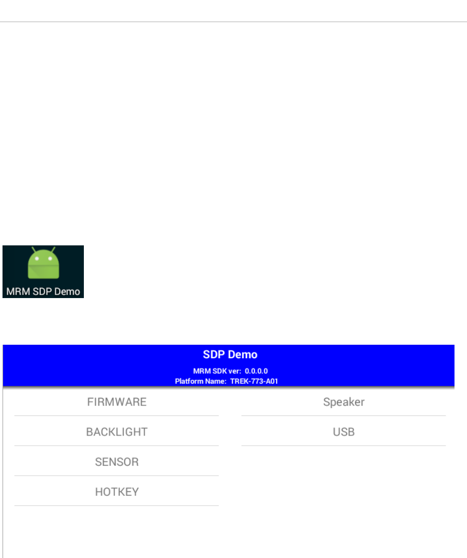
8 SDP Demonstration
The SDP sample APP (SDPSample.apk) demonstrates the usage of SDP APIs. You can tap on the items
in the list to start demo. The following sections show the usage guide line of basic items.
NOTE:
There might be some functions which are not supported on your device.
For the details of supported functions, please refer to the hardware spec.
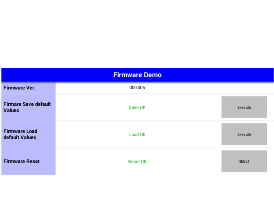
8.1 Firmware
This page demonstrates the Firmware APIs.
To save/load the default settings of SDP firmware, you can press the corresponding "EXECUTE" button.
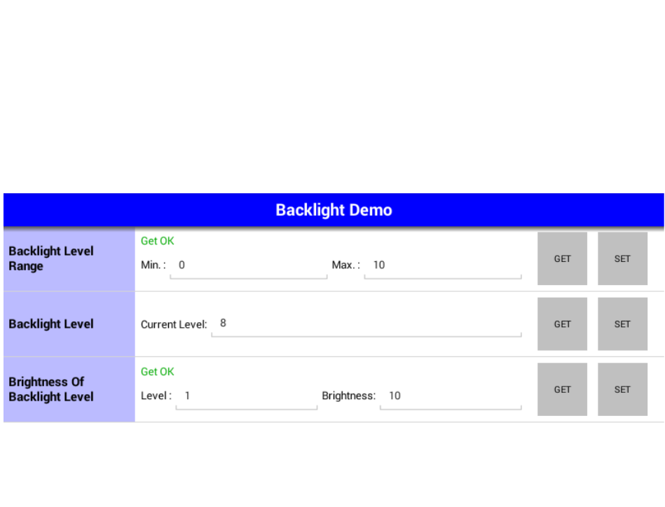
8.2 Backlight
This page demonstrates the Backlight APIs.
Each row shows demonstration different APIs. You can press the buttons at the right side to do
corresponding demo actions.
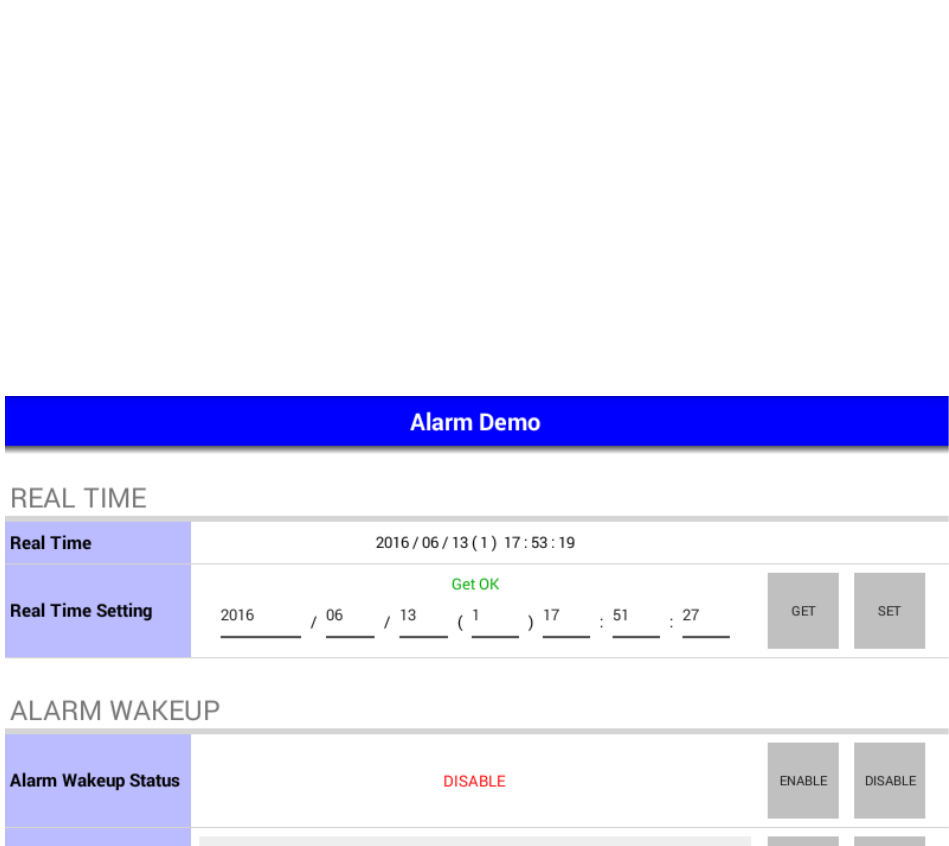
8.3 Alarm
This page demonstrates the Alarm APIs.
Each row shows demonstration different APIs. You can press the buttons at the right side to do
corresponding demo actions.
You can adjust the RTC time and device alarm wakeup setting of VPM in this page.
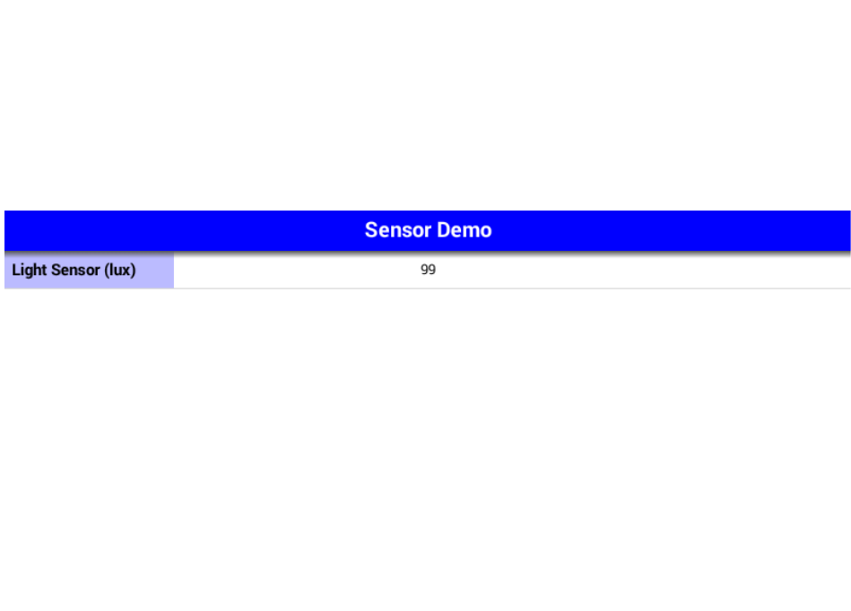
8.4 Sensor
This page demonstrates the Sensor APIs.
The light sensor status is updated periodically.
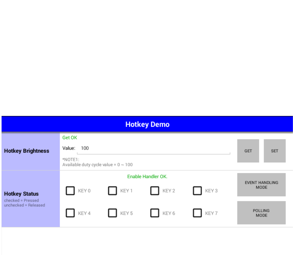
8.5 Hotkey
This page demonstrates the Hotkey APIs.
Each row shows demonstration different APIs. You can press the buttons at the right side to do
corresponding demo actions.
In the row of "Hotkey status", the status of each hotkey will be updated automatically to
corresponding check boxes.
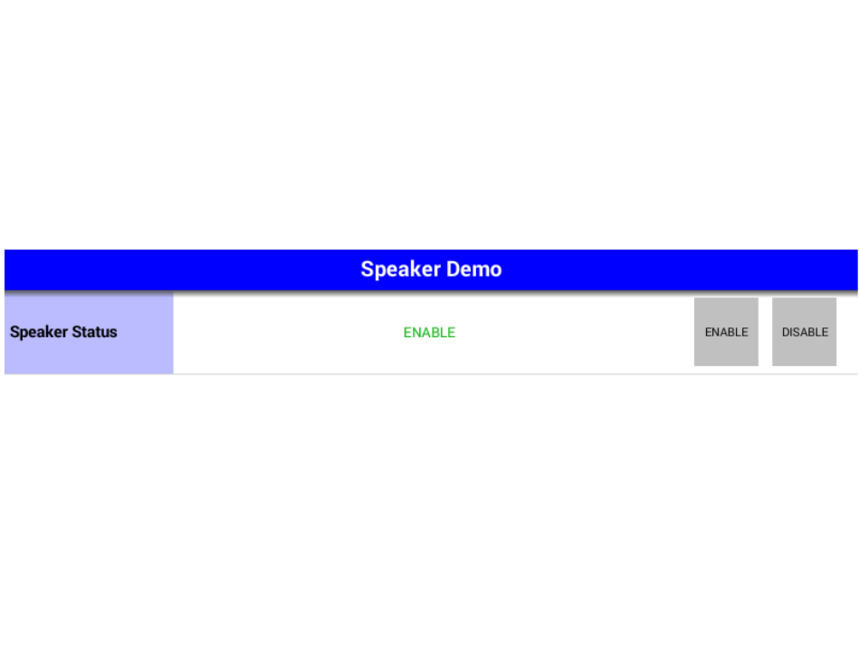
8.6 Speaker
This page demonstrates the Speaker APIs.
Each row shows demonstration different APIs. You can press the buttons at the right side to do
corresponding demo actions.
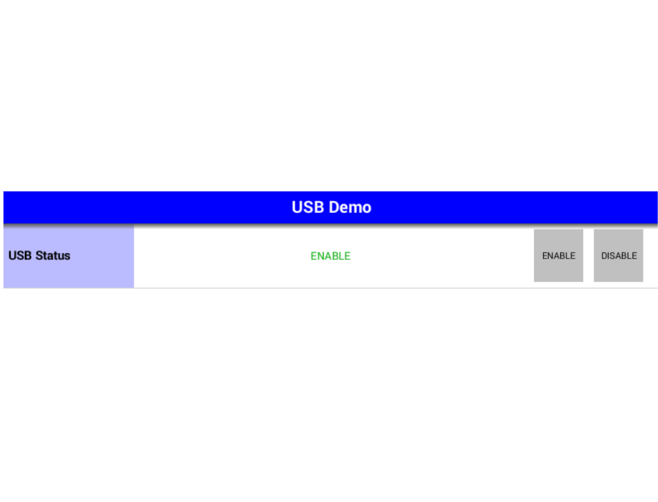
8.7 USB
This page demonstrates the USB APIs.
Each row shows demonstration different APIs. You can press the buttons at the right side to do
corresponding demo actions.

www.advantech.com
Please verify specifications before quoting. This guide is intended for reference
purposes only.
All product specifications are subject to change without notice.
No part of this publication may be reproduced in any form or by any means,
electronic, photocopying, recording or otherwise, without prior written permis-
sion of the publisher.
All brand and product names are trademarks or registered trademarks of their
respective companies.
© Advantech Co., Ltd. 2010