Advantech Co TREK674 Computer User Manual TREK 674 user manaul 20141227
Advantech Co Ltd Computer TREK 674 user manaul 20141227
UserManual.wiki
>
Advantech Co
>
TREK674 User Manual
Manual
Navigation menu
Upload a User Manual
Namespaces
Wiki Guide
HTML
PDF
Info
Views
User Manual
Discussion / Help
Navigation
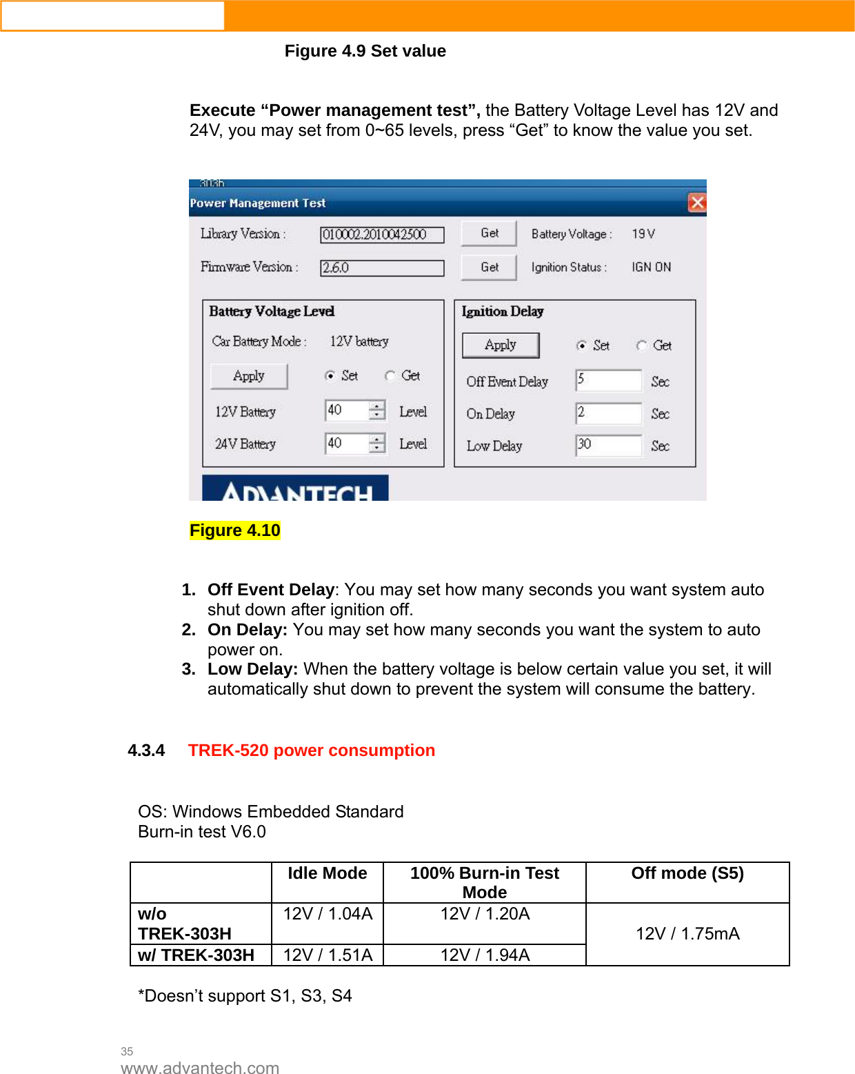
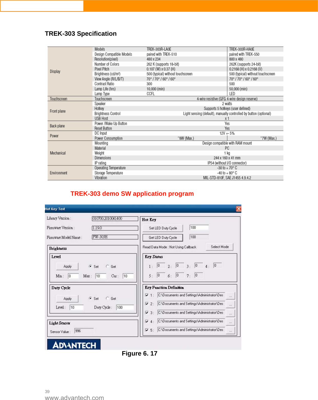
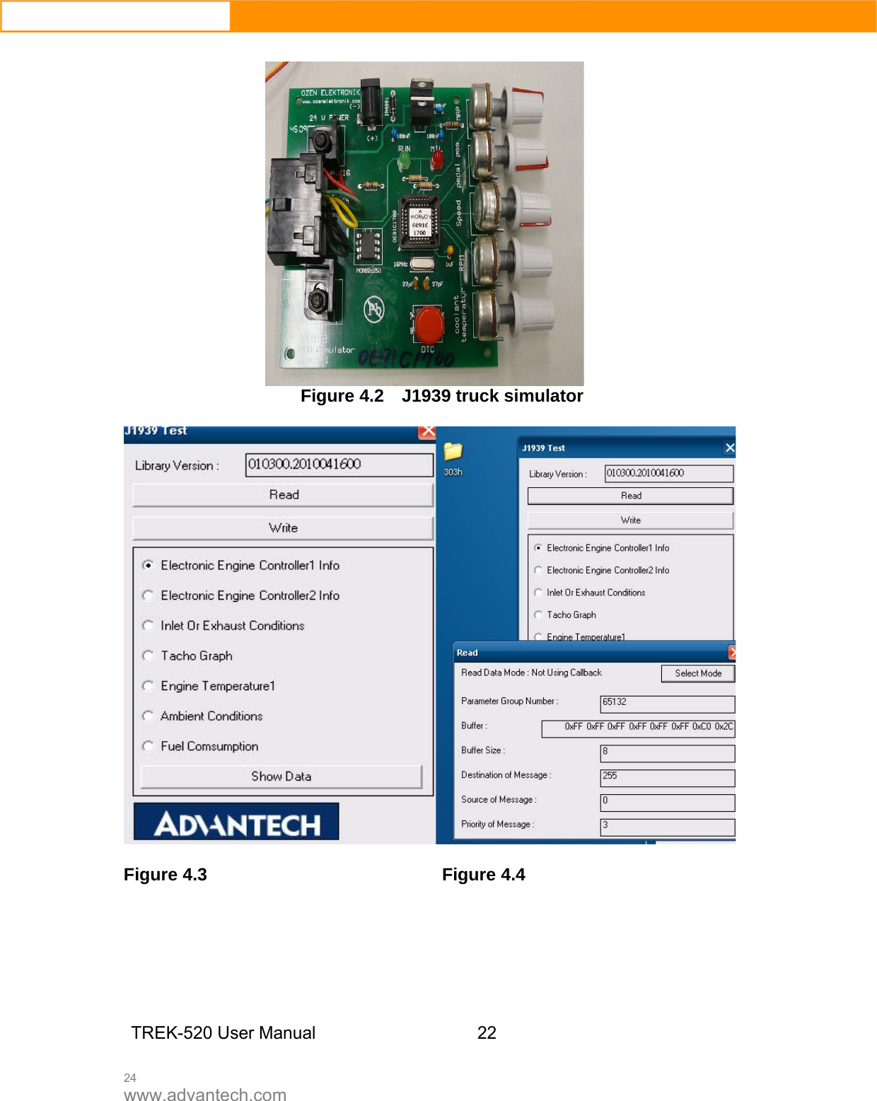
![23 www.advantech.com 4.1 Introduction To make the hardware easier to access for programmers, Advantech has developed an demo program in order to let customer test the functions on TREK-674. This document describes detailed information for each Advantech demo program so that application developers can become more familiar with using them. For technical support, contact Advantech application engineers worldwide. For news updates, visit our website: www.advantech.com 4.1.1 Execute J1939 demo program This section explains how to install the Advantech demo program in Windows XP Pro / Embedded. 1. Execute the test program called “IMC_Demo” Figure 4. 1 2. Click J1939: customer may connect directly to the truck; we use a simulator board below to explain how J1939 protocol can be executed. First, connect to the simulator board to TREK-520 CAN port and console PC, once the simulator is powered on (connect to the truck), you can start getting the data, just click [Read], you may get the data you need from the simulator, click [Read], you may transfer the data to Console Smulator vendor name:](https://usermanual.wiki/Advantech-Co/TREK674/User-Guide-2630567-Page-23.png)
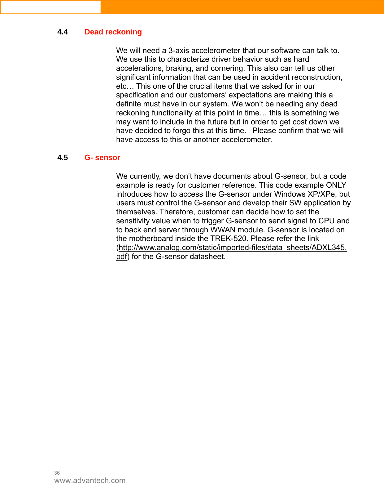
![25 www.advantech.com 4.1.2 CAN Test 1. CAN: Console PC, install [PCAN_USB-to-CAN] test program, and use USB to CAN fixture to connect to TREK-520 CAN port. 2. Execute PCAN-View USB→ Set Baud rate 250kBit/s→ Select [Extended]→OK→ Transmit → New → ID(Hex) key in number → Data key in any number→[Period] key in 100ms→Click [Extended Frame]→OK. See below figure 4. Figure 6. 11 Figure 4. 12 TREK-520 User Manual 22](https://usermanual.wiki/Advantech-Co/TREK674/User-Guide-2630567-Page-25.png)
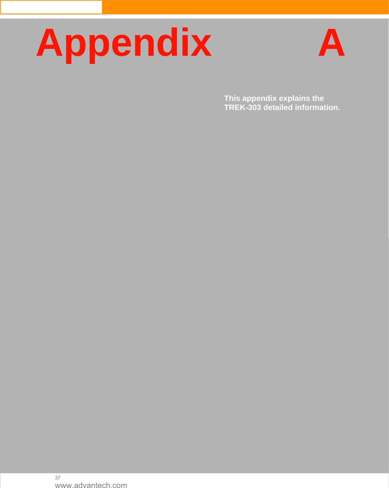
![26 www.advantech.com Figure 4. 13 3. Then you may read the data of TREK-520 from Console PC, in the same time, you may also press [Write Data] to write to Console PC. As for Filter Message, it can filter out the message you don’t need, and keep the message you need. See below Figure 4. Figure 4. 14](https://usermanual.wiki/Advantech-Co/TREK674/User-Guide-2630567-Page-26.png)