Advantech Co TREK688LTE Computer User Manual
Advantech Co Ltd Computer
User manual

User Manual
TREK-688
Computer

TREK-688 User Manual 2
Copyright
The documentation and the software included with this product are copyrighted 2015
by Advantech Co., Ltd. All rights are reserved. Advantech Co., Ltd. reserves the right
to make improvements in the products described in this manual at any time without
notice. No part of this manual may be reproduced, copied, translated or transmitted
in any form or by any means without the prior written permission of Advantech Co.,
Ltd. Information provided in this manual is intended to be accurate and reliable. How-
ever, Advantech Co., Ltd. assumes no responsibility for its use, nor for any infringe-
ments of the rights of third parties, which may result from its use.
Acknowledgements
Intel® and Pentium are trademarks of Intel Corporation.
Microsoft Windows® and MS-DOS are registered trademarks of Microsoft Corp.
All
other product names or trademarks are properties of their respective owners.
Product Warranty (2 years)
Advantech warrants to you, the original purchaser, that each of its products will be
free from defects in materials and workmanship for two years from the date of pur-
chase.
This warranty does not apply to any products which have been repaired or altered by
persons other than repair personnel authorized by Advantech, or which have been
subject to misuse, abuse, accident or improper installation. Advantech assumes no
liability under the terms of this warranty as a consequence of such events.
Because of Advantech’s high quality-control standards and rigorous testing, most of
our customers never need to use our repair service. If an Advantech product is defec-
tive, it will be repaired or replaced at no charge during the warranty period. For out-
of-warranty repairs, you will be billed according to the cost of replacement materials,
service time and freight. Please consult your dealer for more details.
If you think you have a defective product, follow these steps:
1. Collect all the information about the problem encountered. (For example, CPU
speed, Advantech products used, other hardware and software used, etc.) Note
anything abnormal and list any onscreen messages you get when the problem
occurs.
2. Call your dealer and describe the problem. Please have your manual, product,
and any helpful information readily available.
3. If your product is diagnosed as defective, obtain an RMA (return merchandize
authorization) number from your dealer. This allows us to process your return
more quickly.
4. Carefully pack the defective product, a
fully-completed
Repair and Replacement
Order Card and a photocopy proof of purchase date (such as your sales receipt)
in a shippable container. A product returned without proof of the purchase date
is not eligible for warranty service.
5. Write the RMA number visibly on the outside of the package and ship it prepaid
to your dealer.
Part No. 2008T68800 Edition 1
Printed in Taiwan November 2015

3 TREK-688 User Manual
Declaration of Conformity
CE
This product has passed the CE test for environmental specifications. Test conditions
for passing included the equipment being operated within an industrial enclosure. In
order to protect the product from being damaged by ESD (Electrostatic Discharge)
and EMI leakage, we strongly recommend the use of CE-compliant industrial enclo-
sure products.
FCC Class B
Note: This equipment has been tested and found to comply with the limits for a Class
B digital device, pursuant to part 15 of the FCC Rules. These limits are designed to
provide reasonable protection against harmful interference in a residential installa-
tion. This equipment generates, uses and can radiate radio frequency energy and, if
not installed and used in accordance with the instructions, may cause harmful inter-
ference to radio communications. However, there is no guarantee that interference
will not occur in a particular installation. If this equipment does cause harmful interfer-
ence to radio or television reception, which can be determined by turning the equip-
ment off and on, the user is encouraged to try to correct the interference by one or
more of the following measures:
̗ʳʳʳʳʳʳʳʳʳ
Reorient or relocate the receiving antenna (cable over 20 CM)
Increase the separation between the equipment and receiver.
Connect the equipment into an outlet on a circuit different from that to which the
receiver is connected.
Consult the dealer or an experienced radio/TV technician for help.
FCC Caution :
Any changes or modifications not expressly approved by the party responsible for
compliance could void the user's authority to operate this equipment.
FCC RF Radiation Exposure Statement :
1. This Transmitter must not be co-located or operating in conjunction with any other
antenna or transmitter.
2. This equipment complies with FCC RF radiation exposure limits set forth for an
uncontrolled environment.
This equipment should be installed and operated with a minimum distance of 20
centimeters between the radiator and your body.
According to FCC 15.407(e), the device is intended to operate in the frequency band
of 5.15GHz to 5.25GHz under all conditions of normal operation. Normal operation of
this device is restricted to indoor used only to reduce any potential for harmful
interference to co-channel MSS operations.
Technical Support and Assistance
1. Visit the Advantech web site at
http://support.advantech.com
where you can find
the latest information about the product.
2. Contact your distributor, sales representative, or Advantech's customer service
center for technical support if you need additional assistance. Please have the
following information ready before you call:
– Product name and serial number
– Description of your peripheral attachments
– Description of your software (operating system, version, application software,
TREK-688 User Manual 4
etc.)
– A complete description of the problem
– The exact wording of any error messages

5 TREK-688 User Manual
Warnings, Cautions and Notes
Warning! Warnings indicate conditions, which if not observed, can cause personal
injury!
Caution! Cautions are included to help you avoid damaging hardware or losing
data. e.g.
There is a danger of a new battery exploding if it is incorrectly installed.
Do not attempt to recharge, force open, or heat the battery. Replace the
battery only with the same or equivalent type recommended by the man-
ufacturer. Discard used batteries according to the manufacturer's
instructions.
Note! Notes provide optional additional information.
Document Feedback
To assist us in making improvements to this manual, we would welcome comments
and constructive criticism. Please send all such - in writing to: support@advan-
tech.com
Packing List
Before setting up the system, check that the items listed below are included and in
good condition. If any item does not accord with the table, please contact your dealer
immediately.
Partnumber Description Q`ty
TREKͲ688ComputingBox 1
1750007927Ͳ01 2in1(WWAN+GPS)Antenna 1
1750007928Ͳ01 WWANAntenna 1
1750007564Ͳ01 WiFi+BT(2.4/5GHz)Antenna 1
1700023051Ͳ01 VIOCable 1
1700023050Ͳ01 GIOCable 1
1700022702Ͳ01 VideoCable 2
1700019031 Powercable(2M) 1
1700020123 USBCable 1
9680001742 HDD/SSDTraykeylock 1

TREK-688 User Manual 6
Ordering Information
P/N Description
TREKͲ688Ͳ7LWB7PA0E i7Ͳ4650U/LTE/HSPA+(EU)/GPS/WLAN/BT/SSD/Win7Pro
TREKͲ688Ͳ7LWB7PB0E i7Ͳ4650U/LTE/HSPA+(US)/GPS/WLAN/BT/SSD/Win7Pro
Safety Instructions
1. Read these safety instructions carefully.
2. Keep this User Manual for later reference.
3. Disconnect this equipment from any AC outlet before cleaning. Use a damp
cloth. Do not use liquid or spray detergents for cleaning.
4. For plug-in equipment, the power outlet socket must be located near the equip-
ment and must be easily accessible.
5. Keep this equipment away from humidity.
6. Put this equipment on a reliable surface during installation. Dropping it or
letting
it
fall may cause damage.
7. Do not leave this equipment in an environment unconditioned where the storage
temperature under -40° C (-40° F) or above 80° C (176° F), it may damage the
equipment. Operating temperature: -30° C ~55° C.
8. The openings on the enclosure are for air convection. Protect the equipment
from overheating. DO NOT COVER THE OPENINGS.
9. Make sure the voltage of the power source is correct before connecting the
equipment to the power outlet.
10. Position the power cord so that people cannot step on it. Do not place anything
over the power cord. The voltage and current rating of the cord should be greater
than the voltage and current rating marked on the product.
11. All cautions and warnings on the equipment should be noted.
12. If the equipment is not used for a long time, disconnect it from the power source
to avoid damage by transient overvoltage.
13. Never pour any liquid into an opening. This may cause fire or electrical shock.
14. Never open the equipment. For safety reasons, the equipment should be
opened only by qualified service personnel.
15. If one of the following situations arises, get the equipment checked by service
personnel:
̗ʳ
The power cord or plug is damaged.
̗ʳ
Liquid has penetrated into the equipment.
̗ʳ
The equipment has been exposed to moisture.
̗ʳ
The equipment does not work well, or you cannot get it to work according to
the user's manual.
̗ʳ
The equipment has been dropped and damaged.
̗ʳ
The equipment has obvious signs of breakage.
16. CAUTION: The computer is provided with a battery-powered real-time clock cir-
cuit. There is a danger of explosion if battery is incorrectly replaced. Replace

TREK-688 User Manual 6
only with same or equivalent type recommended by the manufacture. Discard
used batteries according to the manufacturers instructions.
17. THE COMPUTER IS PROVIDED WITH CD DRIVES COMPLY WITH APPRO-
PRIATE SAFETY STANDARDS INCLUDING IEC 60825.
18. This device complies with Part 15 of the FCC rules. Operation is subject to the
following two conditions:
(1) this device may not cause harmful interference, and
(2) this device must accept any interference received, including interference that
may cause undesired operation.
19. CAUTION: Always completely disconnect the power cord from your chassis
whenever you work with the hardware. Do not make connections while the
power is on. Sensitive electronic components can be damaged by sudden
power surges.
20. CAUTION: Always ground yourself to remove any static charge before touching
the motherboard, backplane, or add-on cards. Modern electronic devices are
very sensitive to static electric charges. As a safety precaution, use a grounding
wrist strap at all times. Place all electronic components on a static-dissipative
surface or in a static-shielded bag when they are not in the chassis.
21. CAUTION: Any unverified component could cause unexpected damage. To
ensure the correct installation, please always use the components (ex. screws)
provided with the accessory box.
22. Caution text concerning lithium batteries:
23. "Rack Mount Instructions - The following or similar rack-mount instructions are
included with the installation instructions:
A) Elevated Operating Ambient - If installed in a closed or multi-unit rack
assembly, the operating ambient temperature of the rack environment may
be greater than room ambient. Therefore, consideration should be given to
installing the equipment in an environment compatible with the maximum
ambient temperature (Tma) specified by the manufacturer.
B) Reduced Air Flow - Installation of the equipment in a rack should be such that
the amount of air flow required for safe operation of the equipment is not
compromised.
C) Mechanical Loading - Mounting of the equipment in the rack should be such
that a hazardous condition is not achieved due to uneven mechanical load-
ing.
D) Circuit Overloading - Consideration should be given to the connection of the
equipment to the supply circuit and the effect that overloading of the circuits
might have on over current protection and supply wiring. Appropriate consid-

eration of equipment nameplate ratings should be used when addressing this
concern.
E) Reliable Earthing - Reliable earthing of rack-mounted equipment should be
maintained. Particular attention should be given to supply connections other than
direct connections to the branch circuit (e.g. use of power strips)."
24. CAUTION :
To avoid any possible accident, please following instructions to operate this unit.
25. CAUTION :
Only the qualified engineer by Advantech Co.,Ltd can perform the installation in
a vehicle. Improper installation can injure the operator or damage the vehicle
and/or TREK-688 computer system.
Follow the installation as below to avoid overloading the circuit after adding this
device.
Follow the instructions below to properly install the TREK-688 computing system
in a vehicle.
z Determine the best location for mounting the unit taking into consideration
the driver`s field of view and ease of accessing the unit. (Only install this
unit in the car passenger compartment. Suggested locations are next to
driver`s seat or located on center console.)
z Connect the vehicle computer to the vehicle`s wiring system as below.
Routing Electrical Cables
Establish a near route for the cable, staying clear of moving parts or
hot surfaces whenever possible.
Fix the cable to existing cable runs inside the vehicle using cable ties,
but make sure they are away from any moving or hot surfaces.
When the cabling must go through a panel, use a suitable cable gland.
Ensure the cable does not have tight bends. The minimum
recommended radius is 2.5”.
Ensure cables do not swing or chafe on the structure.
DO NOT wind a cable in and out of the mesh on a cage.
Ensure that all fuses installed as instruction. 32 Volt is suitable for unit.
All power wiring must use the supplied power cable comply with
intended applications of SAE with suitable ratings of electrical,
temperature, exposure and flammability.
Fuses : UL LISTED Fuse for Automobile use.
- A 10 amp.
Keep the path between the battery and the vehicle computer as short
as possible and away from any part of the ignition high tension system.
A 10 amp. If your car exhibits electrical problems, the fuse may blow and
shut the system down to protect it from damage. Once the problem is
rectified, replace the blown fuse and the system should again be operational.
TREK-688 User Manual 8
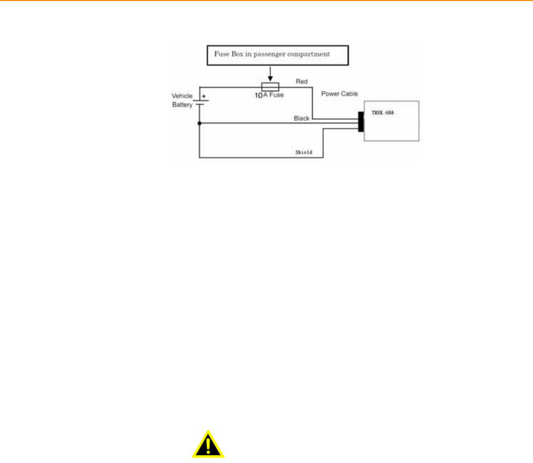
Connecting the Power Cable
1. Disconnect the vehicle battery.
2. Connect the green wire to the vehicle`s negative power source.
NOTE see the vehicle Owner`s Manual for specific wiring information.
3. Connect the red wire of Fuse Box in passenger compartment to
vehicle`s positive power source. Connect the black wire to the
vehicle`s negative power source. Then Fuse Box secured to connector.
Insert the female connector of Fuse Box to the male connector of
TREK-688 vehicle system. Connect the Orange wire to the vehicle`s
ignition switch.
4. Ensure the wiring connections created are sufficiently insulated from
each other.
5. Re-connect the vehicle battery.
6. Insert the power cable connector into TREK-688 computing system
power port. Align the keyway on the power connector with the notch on
the vehicle computer`s power port.
CAUTION
Do not open the cover on the front side as illustration as below before
turning off the power.
Safety Precaution - Static Electricity
Follow these simple precautions to protect yourself from harm and the products from
damage.
̗
ʳTo avoid electrical shock, always disconnect the power from your PC chassis
before you work on it. Don't touch any components on the CPU card or other
cards while the PC is on.
̗
ʳDisconnect power before making any configuration changes. The sudden rush
of power as you connect a jumper or install a card may damage sensitive elec-
tronic components.
This product is intended to be supplied by a Listed DC power source, rated
9~32Vdc, 7A minimum and Tma 55 degree C, if need further assistance with
purchasing the DC power source, please contact Advantech for further information.
Warning! 1. Input voltage rated: 9 ~ 32 Vdc.

2. Transport: carry the unit with both hands and handle with care.
3. Maintenance: to properly maintain and clean the surfaces, use only
approved products or clean with a dry applicator.
4. CFast: Turn off the power before inserting or removing
CFast storage cards.

TREK-688 User Manual 1
Contents
Chapter 1 General Information ............................1
1.1 Introduction
...............................................................................................
2
1.2 General
Specifications ..............................................................................
3
1.3 Dimensions
...............................................................................................
5
Figure 1.1 TREK-688
dimensions................................................
5
Chapter
2
System
Setup
.......................................7
2.1
2.2
A Quick Tour of the TREK-688 Computing
Box
........................................
8
Figure 2.1 Front view of
TREK-688 .............................................
8
Figure 2.2 Rear view of
TREK-688
..............................................
8
2.1.1 Installing CFast & SIM card…
...........................................................
9
2.1.2 Installing Storage……………………………………………………10
Installation Procedures
2.3
2.2.1 Connecting the Power
Cord
..........................................................
9
Table 2.1: Pin Definition of Power Cord
......................................
9
2.2.2 Power
Connector ..........................................................................
9
Figure 2.6 Power connector
outlook
............................................
9
Table 2.2: Pin
Definition
of
Power Connector (Molex
Manufacturer
Part
no.0430451200)
................................................
10
Figure 2.7 Power connector photo
............................................
10
Running the BIOS Setup
Program
..........................................................
10
Chapter
3
Switches setting and I/O Connectors………. ..13
3.1 Setting Switches…………………………………………
....................................
13
3.1.1 Switches List……………………………............................................
13
3.2
3.3
3..1.2 Switch Location………………..................................................................
1
3
3.1.3 Switch Setting……………………………………………………...........
13
3.1.3.1 MiniPCIe (WWAN) Power Voltage Setup (SW2)…………………13
3.1.3.2 MiniPCIe(WWAN) Support WWAN Module Setup (SW3)………13
3.1.3.3 CAN BUS Termination(Only for test use)(SW6)…………………14
3.1.3.4 MiniPCIe(WWAN) Power Voltage Setup (SW8)…………………14
3.1.3.5 MiniPCIe(WWAN) Support WWAN Module Setup(SW9)……….14
3.1.3.6 I/O DB9 PIN9 Select (ON TOP LAYOUT)(CN15)………………..14
LED Indicator………………………………………………………………….14
I/O Connectors Pin Assignment……………………………………..……..15
3.3.1 Power Connector………………………………………………………15
3.3.2 HDMI Connector………………………………………………………..15
3.3.3 Smart Display Connector……………………………………………..16
3.3.4 USB Connector (Rear side)…………………………………………..17
3.3.5 USB Connector (Front side)………………………………………….18
3.3.6 VGA & RS-232 Connector……………………………………………19
3.3.7 Video Input Connector………………………………………………..20
3.3.8 Vehicle I/O Connector…………………………………………………21
3.3.9 Generic I/O Connector………………………………………………..22
3.3.10 LAN Connector……………………………………………………….23

Chapter 4 Software Demo Utility
Setup...............
29
4.1 Introduction………………………………………………………………………30
4.2 IVCP Demonstration…………………………………………………………….30
4.2.1 Information…………………………………………………………………30
4.2.2 Mode Control………………………………………………………………31
4.2.3 Low voltage Protection……………………………………………………32
4.2.4 Event Delay………………………………………………………………...33
4.2.5 Alarm………………………………………………………………………..34
4.2.6 Watchdog…………………………………………………………………..35
4.2.7 G-Sensor…………………………………………………………………..36
4.2.8 Peripheral………………………………………………………………….37
4.2.9 Storage……………………………………………………………………..38
4.2.10 Digital IO………………………………………………………………….39
4.2.11 P-sensor………………………………………………………………….40
4.3 VCIL Demonstration…………………………………………………………….41
4.3.1 Port selection………………………………………………………….….41
4.3.2 Information…………………………………………………………….….42
4.3.3 Option…………………………………………………………………..….43
4.3.4 CAN/J1939/OBD2/J1708/J1587………………………………………..44
4.4 Smart Display Demonstration……………………………………………….…45
4.4.1 Information…………………………………………………………….….46
4.4.2 Backlight………………………………………………………………..….47
4.4.3 Hot Key………………………………………………………………….…48
4.4.4 Peripheral……………………………………………………………….…49
4.5 GPS Demonstration………………………………………………………….….50
4.5.1 Port selection……………………………………………………………...50
4.5.2 Information…………………………………………………………………51
4.5.3 NEMA………………………………………………………………………52
Appendix A TREK-303…………………………………53
A.1 TREK-303 Specification………………………………………………….……..54
Table A.1 TREK-303 Specification…………………………………….54
Table A.2 Smart Display Connector……………………………………55
Figure A.1 Hotkey utility…………………………………………………..56

TREK-688 User Manual 1
Chapter 1
1 General Information
This chapter gives background
information on the TREK-688
Premium In- Vehicle Computing Box.
Sections include:
̗ʳ
Introduction
̗ʳ
General Specifications
̗ʳ
Dimensions
TREKͲ688UserManual
1.1 Introduction
TREK-688 is an industrial-grade, powered by Intel® Haswell 4th generation dual core CPU
computing box designed to provide high quality video surveillance and fleet management
for eBus and BRT( Bus Rapid Transit). It can work in extreme environments with features
like the wide working temperature range (-30-55ɗ) and anti-shock/vibration to pass MIL-
STD-810G and 5M3 standard. Its special power protection surges from impacting the
system. Guarding against damage from transient car power.
TREK-688 combined with variety of I/O connectors can be connected to devices like
TPMS (Tire Pressure Monitoring System), Rear view Camera ( for parking monitoring)
and CAN Bus devices. It has dual CAN BUS ports and support several kind of vehicle
protocols (e.g. J1939,OBD-II) for vehicle diagnostics and driver behavior management.
Build-in wireless communication (WWAN, WLAN,BT) enable TREK-688 to send import
ant driver/vehicle/location/cargo information back to the control center. Furthermore,
TREK-688 also reserved three displays/dual audio interfaces supporting different
resolutions can deliver different applications to different displays; eg:one application to a
fleet driver and another to passenger to IVI and digital signage application.
TREK-688 I/O Overview

TREK-688 User Manual 4
Chapte
r
1 General Information
1.2 General Specifications
Features
Intel®HaswellCore™i7Dualcorehighperformanceprocessorformultitasking.
Embeddedvideoencodersupportsupto12analogvideoinputsforD1,30fpsresolutionand8audioinputs
DualexternalHDD/SSDtraywithkeyͲlockprotection.
EasilypairedwithTREKinͲvehiclesmartdisplaysviaasingleͲcableconnection.
Intelligentvehiclepowermanagementsystemforignitionon/off/delayandpowerprotectionfunctions.
VehiclediagnosticinterfacewithconfigurabledualCAN(J1939,OBDͲII/ISO15765)andJ1708protocols.
BuiltͲinLTE/GNSS/WLAN/BT(withdualSIMcards)modules.
AdvancedShock&antiͲvibrationcertifiedbyMILͲSTDͲ810G,EN60721Ͳ3(5M3)
Richmanagement&videoSDK,testutilityforcustomerevaluating.
Specifications
Processor Intel®Core™i7Ͳ4650UDualCore,2.9GHz(i3Ͳ4010U&i5Ͳ4300Uby
projectsupport)
Memory
1xSOͲDIMMsocket
Upto8GBDDR3LͲ1600NonͲECCmemorymodule;(Default
configuration:4GB)
Graphic IntelHDgraphics44001.1GHz
VideoHWEncoder StretchS7,supportH.264,MJPEGformat;ResolutionuptoD1,30fps
perchannel
Core
O.S Windows7pro32bitasdefault.WES7,WE8S32bitbyprojectsupport
LinuxFedora18Remix(kernel3.8.0)(32Ͳbit)byprojectsupport
CFast 1xexternalaccessibleCFastslotwithcover,supportsystembootup
Defaultconfiguration:16GB,SLCSQFlashCFastcard
mSATA 1xmSATAslot,supportsystembootup
Defaultconfiguration:N/A;BOMoptional,byprojectͲbased
Storage
HDD/SSD
2xexternalaccessible2.5"MobileHDD/SSDtraywithkeyͲlock
protection,supportsystembootup(Optional)
SupportSATAGen2(3Gb/s)
SmartDisplayPort(*1)
12V/2ApoweroutputforTREKͲ30x
1x18ͲbitsLVDS(Resolution:800x480(TREKͲ303),1024x768(TREKͲ
306);defaultTREKͲ306)
1xLineͲOut(*2)(ForSpeakersonTREKͲ30x)
2xUART(TX/RX,TX/RX/RTS)(ForT/S,Hotkeys,brightness,light
sensorcontrol)
1xUSB2.0TypeA
1xPWRButtonSignal
1xResetButtonSignal
HDMI 1xHDMI1.3b(Resolutionupto1920x1080)
Display
VGA 1xDB15(Resolutionupto2560x1600)
VehicleI/OPort 2xCANBus(SupportRawCAN,J1939,OBDͲII/ISO15765;FW
configurable)
1xJ1708(SupportJ1587)
1x4ͲwireRSͲ232/422/485(DefaultRSͲ485,bysoftwaresetting)
GenericI/OPort 2x4ͲwireRSͲ232
4xIsolatedDI(DryContact)
4xIsolatedDO(Opencollectoroutput,drivingbyrelay)
1xLineͲOut(*2)
1xMicͲIn
StandardI/OPort 1xUSB2.0TypeA(Frontside)
2xUSB3.0TypeA(Rearside,withcableclip)
1xHighSpeedFullRSͲ232,DBͲ9(Pin9=Ring,12V/5V@0.5AisBOM
optionalbyjumpersetting)
2xGigaLAN,with8ͲpinM12connector
I/O
Video/Audioinput 16ͲchVideoinputs,VideoCompression:supportH.264,MJPEG

5 TREK-688 User Manual
(AV1&AV2,viadual
DVIͲIconnector)
format;ResolutionuptoD1,30fpsperchannel,total480fps.
8ͲchmonoAudioinputs,AudioCompression:G.711
LED 6xLEDs(Power(Red),CFast(Yellow),WLAN(Green),WWAN(Green),
GPS(Yellow),Networkconnection(Yellow))
PowerButton ViaTREKͲ30x(InͲVehicleSmartDisplay);Systemispoweredonby
Ignitionindefault
ResetButton 1xResetbutton(Frontside)
WLAN+Bluetooth IEEE802.11a/b/g/n+Bluetooth4.0combomoduleviaFullMiniͲPCIe
Slot
WWAN 4G(LTE,HSPA+,GSM/GPRS/EDGE,EVͲDOReva1,1xRTT):Sierra
WirelessMC73xxviaFullMiniͲPCIeSlot
(Default:MC7354forUS/MC7304forEU)
GNSS BuildͲinuͲbloxMAXͲM8WGPS/Glonass/Beidoumodule,supportAGPS
RF
Antenna 4xSMAtypeantennaholeforGPS,WiFI+BT,WWAN/LTEMIMO.(*3)
Voltageinput Supports12/24Vcarpowersystem.(9V~32VwideDCinput,ISO
7637Ͳ2&SAEJ1113compliant.)
Power
IntelligentVehicle
Power
Management(iVPM2.0)
Systempoweron/off/hibernatemanagement(e.g.Programmable
IgnitionOn/OffTimedelay)
SupportWakeupEvents:
ͲAlarm(RTC)Wakeup.
ͲWakeupbyCall/SMS.
ͲWakeupbyGͲsensor.
Systempowerprotection(e.g.CarBatteryLowVoltageProtection)
Systemmonitoringanddiagnostic
Dimensions(WxHxD) 346x92.5x196.2mm
Mechanical Weight 5.9kg(withtwoHDDs)
IPRating IP30
Vibration/Shock MILͲSTDͲ810G,EN60721Ͳ3(5M3)
EMC CE,FCC
Safety UL/cUL,CB
VehicleRegulation EͲMark(E13),SAEJ1455classC,ISO7637Ͳ2,SAEJ1113,EN50155,IEC
60571
RFRegulation CE(R&TTE),FCCID
OperatingTemperature Ͳ30°C~55°C
Environment
StorageTemperature Ͳ40°C~80°C
*1:TobepairedwithTREKͲ303/306directly.(SingleͲcableconnection)
*2:Supportdualindependentaudiostreams.(i.e.TheLineͲOutinterfacein"SmartDisplayPort"and
"GenericI/OPort"aredrivenbydifferentAudiocodecs.)
*3:TheconnectortypeonboxsideisFemaleRPͲSMAconnector.(i.e.Femaleconnectorbody(outside
threads)withamaleinnerpincontact.)
TREK-688 User Manual 6
Chapte
r
1 General Information
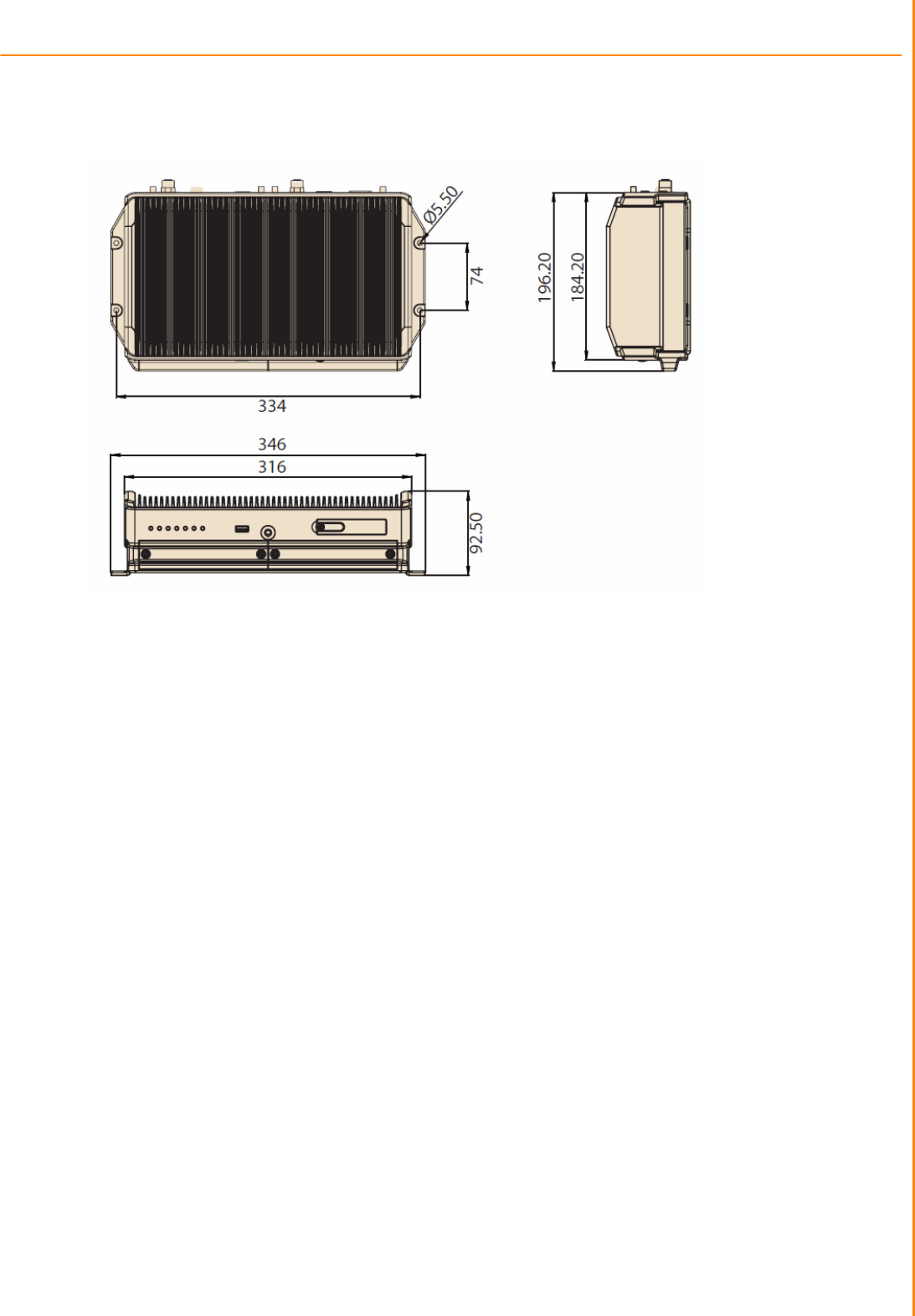
1.3 Dimensions
Figure 1.1 TREK-688 dimensions

Chapter 2
2 System Setup
This chapter details system setup
on TREK-688
Sections include:
ʳ
A Quick Tour of the Computer
Box
ʳ
Installation Procedures
ʳ
Running the BIOS Setup
Program
TREK-688 User Manual 8
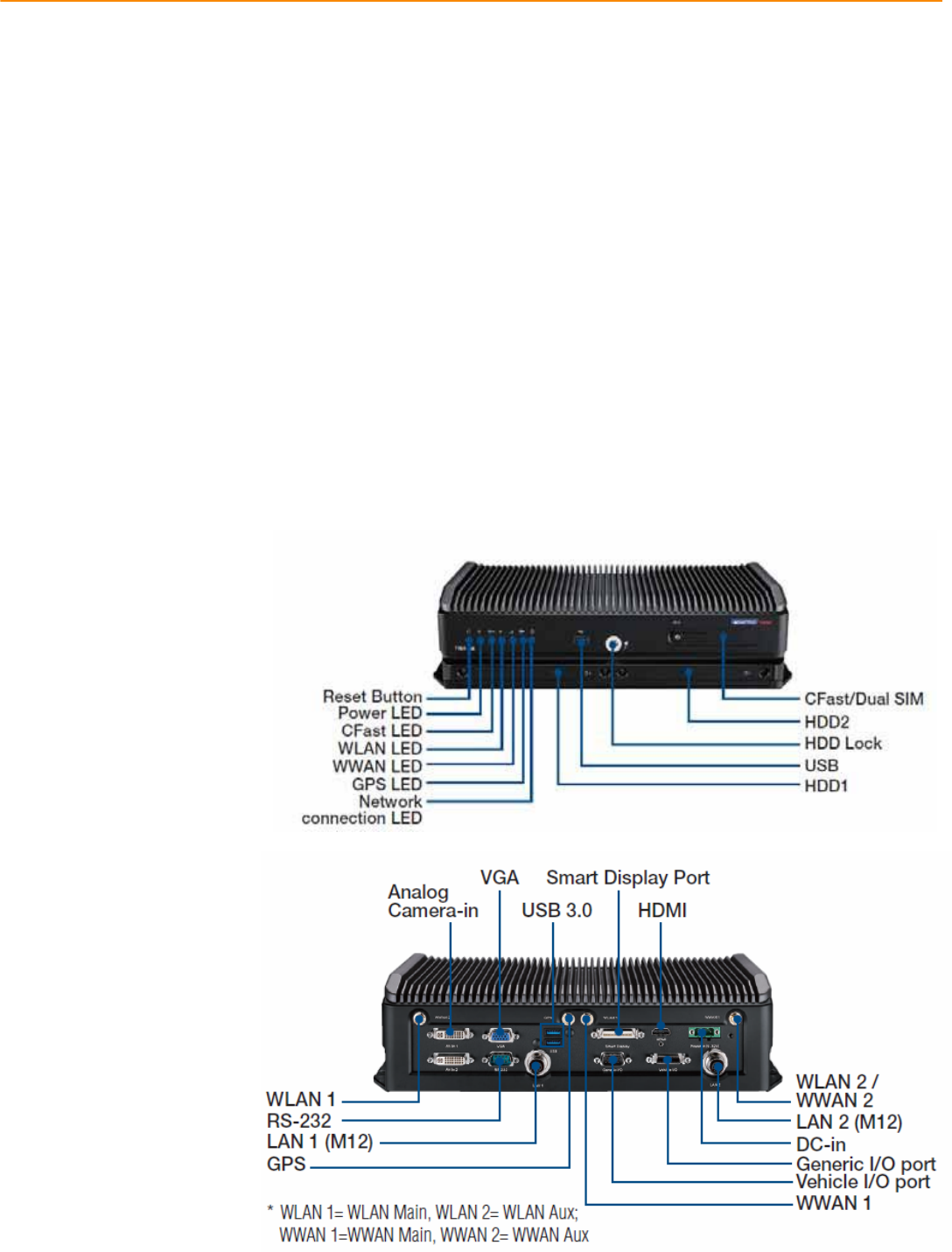
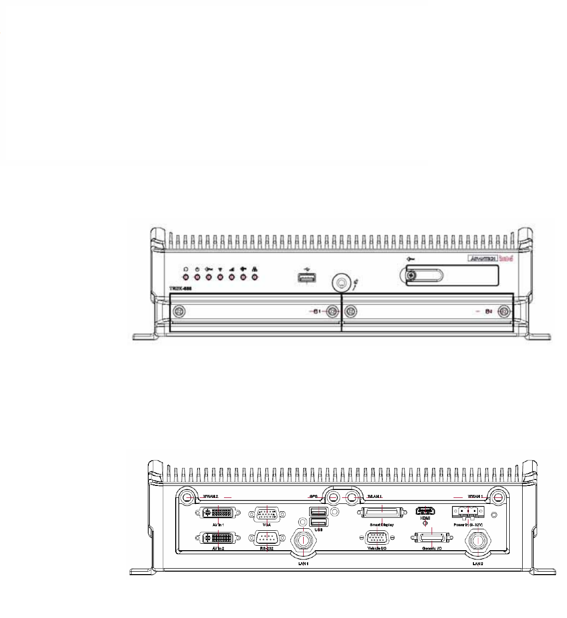
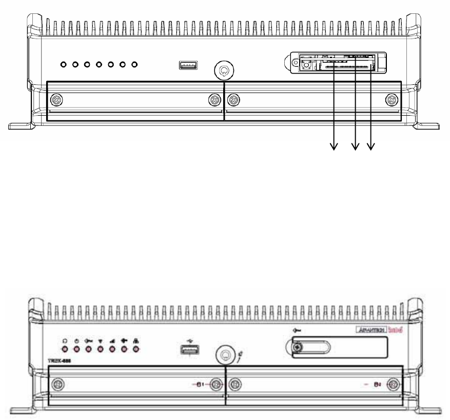
2.1 A Quick Tour of the TREK-688 Computing Box
Before starting to set up the In-Vehicle Computing Box, take a moment to become
familiar with the locations and functions of the controls, drives, connectors and ports,
which are illustrated in the figures below.
Figure 2.1 Front view of TREK-688
Figure 2.2 Rear view of TREK-688
9 TREK-688 User Manual
2.1.1 Installing CFast Card & SIM card
RemoveCFastdoorscrewandcaninstallCFastCard&SIMCarddirectly.PleaseinsertSIMCardfromSIM1
slotbecausedefaultpriorityisSIM1.IfyouinserttoSIM2slot,youhavetomodifysettingofSDK.
Figure 2.3 Installing CFast card & SIM card
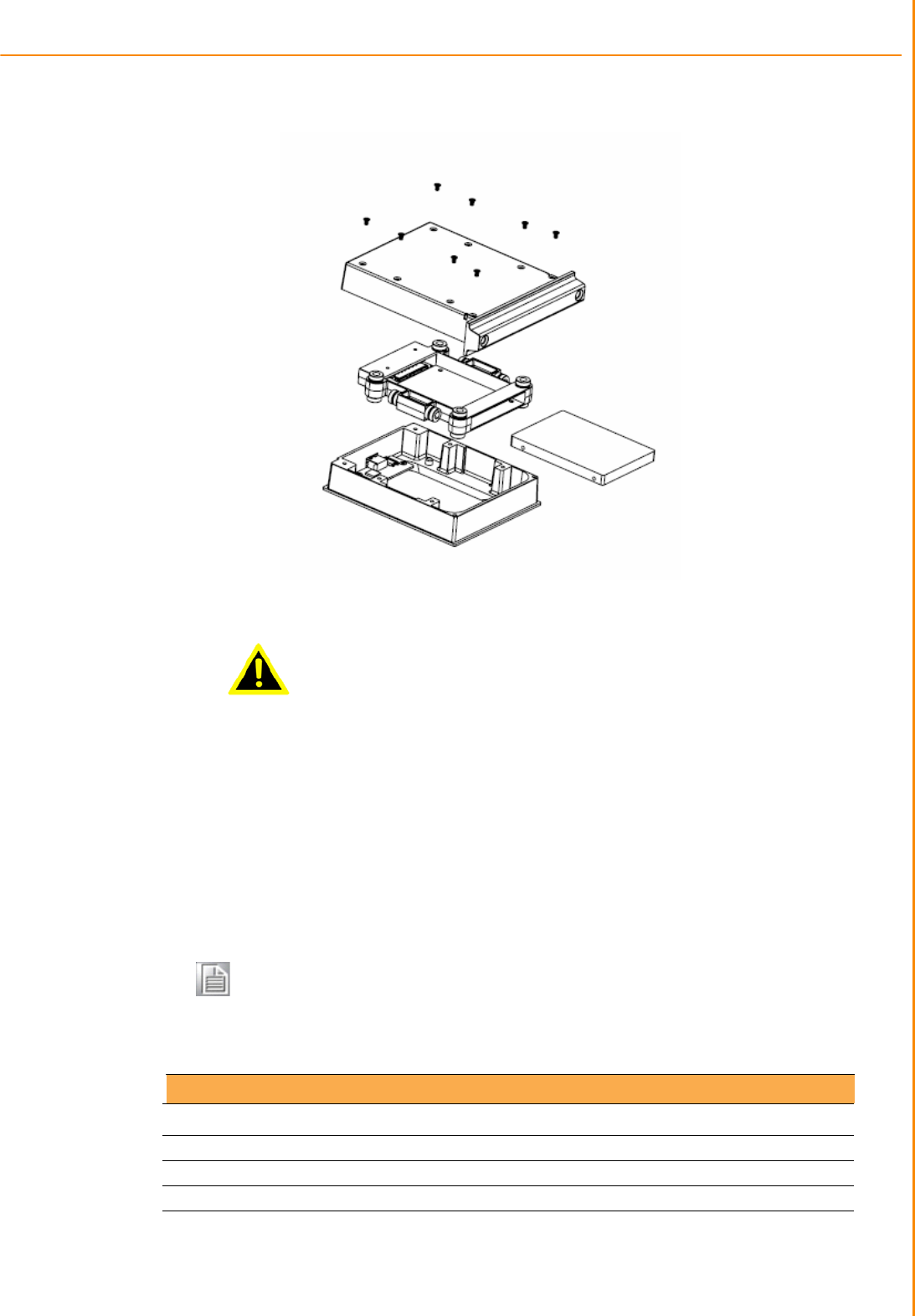
2.1.2 Installing Storage
1. Release2pcsscrewsofeachHDD/SDDTrayandpulloutthetray.
2. Remove8pcsscrewsofHDD/SSDtraytopcoverandtakeouttheHDD/SSDframe.InsertHDD/SSDintothe
frameandfixby4pcsscrews.
3. FixHDD/SSDtraytopcoverby8pcsscrews.
SIM1 SIM2 CFastCard
TREK-688 User Manual 1
Chapte
r
2 System Setup
Warning! Do not remove the HDD/SSD tray when system running.
Power must be switched off in advance. Take care in
order to avoid injury or damage to the equipment.
2.2 Installation Procedures
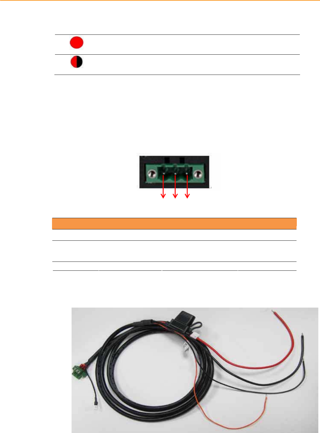
2.2.1 Connecting the Power Cord
Connect the three pin waterproof power cord to the DC inlet of the In-Vehicle Com-
puting Box. On the open-wire end, one pin is reserved for positive voltage and is
marked, "+"; one pin is reserved for ground and is marked, "-"; and, one pin is
reserved for the ignition signal with an “ignition” mark.
Note! Ignition on/off setting: The TREK-688 supports an ignition on/off function
so that you can power on/off the TREK-688 via the ignition signal/volt-
age and connect the TREK-688 vehicle ignition switch.
Table 2.1: Pin Definition of Power Cord
Pin Definition Color
1 - Black
2 + Red
3 Ignition Orange
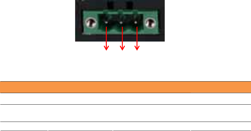
2.2.2
Power Connector
11 TREK-688 User Manual
Figure 2.6 Power connector outlook
Table 2.2: Power connector
Pin Signal Pin Signal
1 Ground 2 Power input
(9~32VDC)
3 Acc ignition input
123

TREK-688 User Manual 1
2.3 Running the BIOS Setup Program
In most cases, the computer will have been properly set up and configured by the
dealer or SI prior to delivery. However, it may still be necessary to adjust some of the
computer's BIOS (Basic Input-Output System) setup programs to change the system
configuration data, like the current date and time, or the specific type of hard drive
currently installed.
The setup program is stored in read-only memory (ROM). It can be accessed either
when turning on or resetting the computer, by pressing the “Del” key on the keyboard
immediately after powering up the computer.
The settings that are specified with the setup program are recorded in a special area of
the memory called CMOS RAM. This memory is backed up by a battery so that it will
not be erased when turning off or resetting the system. Whenever the power is turned
on, the system reads the settings stored in CMOS RAM and compares them to the
equipment check conducted during the power on self-test (POST). If an error occurs,
an error message is displayed on screen, and the user is prompted to run the setup
program.

Chapter 3
4 Switches Setting and
Connectors
This chapter explains how to set
up the In-Vehicle Computing Box
hardware, including instructions
on setting and how to set
switches and read indicators.
Sections include:
Setting Switches
Indicators introduction
I/O connectors pin assignment
TREK-688 User Manual 14
3.1 Setting Switches
It is possible to configure the In-Vehicle Computing Box to match the needs of the
application by resetting the switches.
3.1.1SwitchesList
Switches Description
SW2 MiniPCIe(WWAN)PowerVoltageSetup
SW3 MiniPCIe(WWAN)SupportWWANModuleSetup
SW6 CANBUSTermerater(Onlyfortestuse)
SW8 MiniPCIe(WWAN)PowerVoltageSetup
SW9 MiniPCIe(WWAN)SupportWWANModuleSetup
CN15 I/ODB9PIN9select(ONTOPLATOUT)
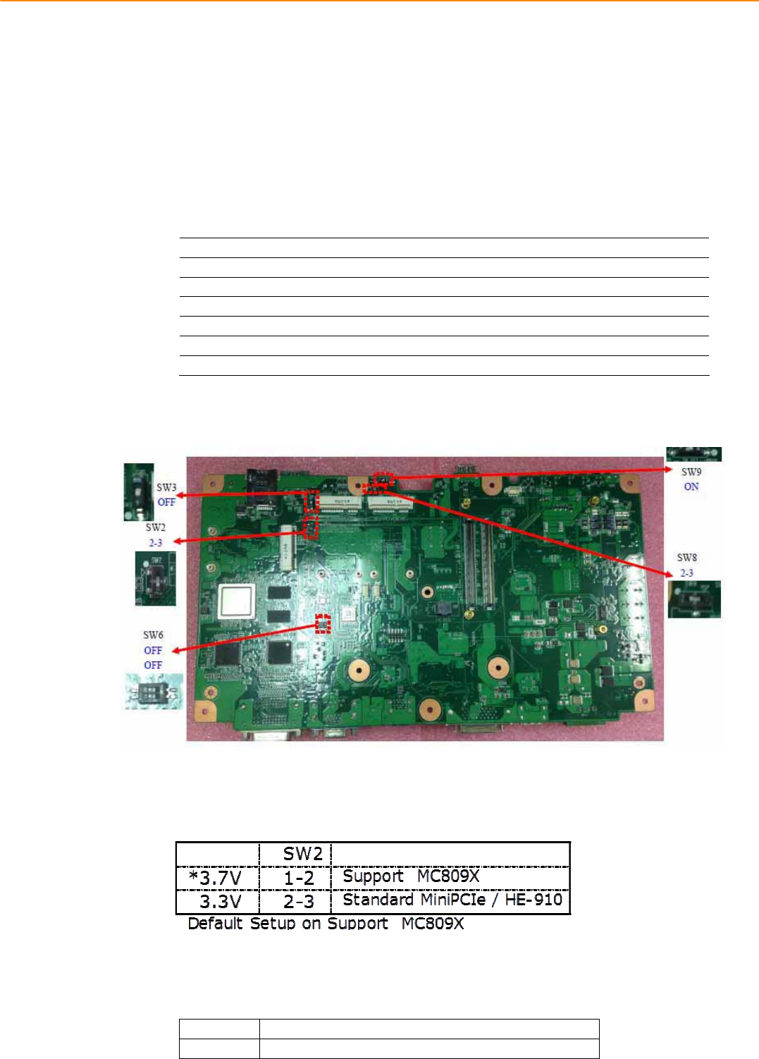
3.1.2SwitchesLocation
3.1.3Switchessetting
3.1.3.1MiniPCIe(WWAN)PowerVoltageSetup(SW2)
3.1.3.2MiniPCIe(WWAN)SupportWWANModuleSetup(SW3)
ON ForstandardMiniPCIe(forWLAN)
OFF SupportLTE/3.5GModule(forWWAN)(Default)
15 TREK-688 User Manual
3.1.3.3CANBUSTermination(Onlyfortestuse)(SW6)
ON/ON Disable(Default)
OFF/OFF EnableCANBUSTerminator
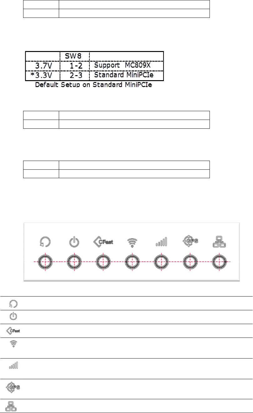
3.1.3.4MiniPCIe(WWAN)PowerVoltageSetup(SW8)
3.1.3.5MiniPCIe(WWAN)SupportWWANModuleSetup(SW9)
ON ForstandardMiniPCIe(forWLAN)(Default)
OFF SupportLTE/3.5GModule(forWWAN)
3.1.3.6I/ODB9PIN9select(ONTOPLAYOUT)(CN15)
1Ͳ2 Ring(Default)
2Ͳ3 Power_+12V/0.5A
3.2 LED Indicator
System Reset
Button
Force the system to reboot.
Power Activity
indicator LED
When the system is in NORMAL mode, this LED will be light
up.(Red color)
CFast Activity
Indicator LED
The storage activity indicator is a green LED, and flashes to show
the activity of CFast.(Orange color)
WLAN Activity
Indicator LED
The WLAN activity indicator is an orange LED, and flashes to
show the activity of the WLAN module.(Green color)
This LED is controlled directly by the WLAN module.
WWAN Activity
Indicator LED
The WWAN activity indicator is a green LED, and flashes to show
the activity of the WWAN module.(Green color)
This LED is controlled directly by the WWAN module.
GPS Activity
Indicator LED
The GPS activity indicator is an orange LED, and is used to show
GPS activity. This LED is controlled directly by the GPS
chips.(Orange color)
LAN Activity
Indicator LED
The LAN activity indicator is a green LED, and flashes to show
the activity of the LAN data transportation. (Green color)
TREK-688 User Manual 16
System power indicator LED
Red LED keep light
Normal mode
System is in NORMAL mode
Red LED flashing
Boot loader mode
F/W can be update
3.3 I/O Connectors Pin Assignment
3.3.1Powerconnector
Table 3.1: Power connector
Pin Signal Pin Signal
1 Ground 2 Power input
(9~32VDC)
3 Acc ignition input
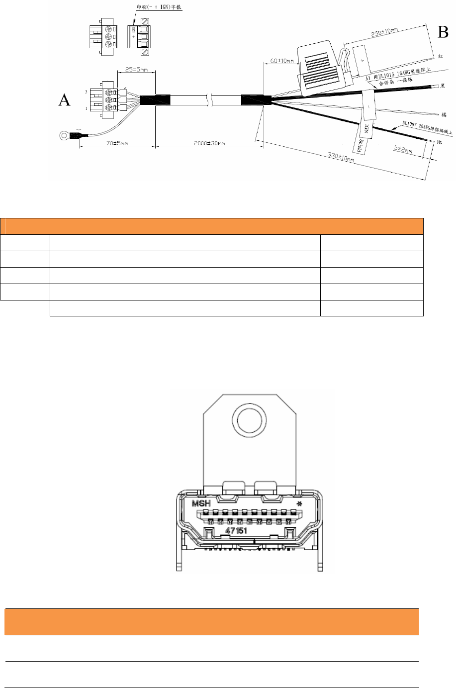
3.3.1.1PowerinJackCable
123
17 TREK-688 User Manual
Connector Type: M12 JACK GT238134-0205Z-JG-01 MALE 5P*1
Table 1: Power
M12 JACK
Cable
Pin
Depiction
PIN Signal Depiction
Cable /Label
1 Power
Ground
႑
/-
2
Power Input (9 ~ 32 VDC)
႑
/+
3
Acc Ignition Input
႑
/IGN
Shield
Ground
႑
/Shield
Fuse Spec: 58V/10A*1
3.3.2HDMIConnector
Connector type: HDMI Conn. 19P 0.5mm 90D(F) SMD 471511002
Table HDMI Connector Pin Assignment
Pin
Signal Depiction
Pin Signal Depiction
1 HDMI_DATA2P 11
GND

TREK-688 User Manual 18
2
GND
12 HDMI_CLKN
3 HDMI_DATA2N 13 NC
4 HDMI_DATA1P 14 NC
5
GND
15
HDMI_CTRLCLK
6 HDMI_DATA1N
16
HDMI_CTRLDATA
7 HDMI_DATA0P
17
GND
8
GND
18
HDMI_Power(5V)
9 HDMI_DATA0N
19
HDMI_HPD
10 HDMI_CLKP
3.3.3SmartDisplayConnector
Table 5.2: Smart Display Connector
Pin Signal Pin Signal
1 Backlight Enable output # 2 Panel Power Enable output #
3 LVDS Ground 4 Reset Button Input #
5 LVDS Clock + 6 LVDS Clock -
7 LVDS Ground 8 LVDS Ground
9 LVDS Data2 + 10 LVDS Data2 -
11 RS232 TXD1 # 12 RS232 RXD1 #
13 LVDS Data1 + 14 LVDS Data1 -
15 LVDS Ground 16 LVDS Ground
17 LVDS Data0 + 18 LVDS Data0 -
19 USB D- 20 USB D+
21 USB Ground 22 USB Ground
23 +12 VDC output (+/- 5%, max 1A) 24 +12 VDC output (+/- 5%, max 1A)
25 +12 VDC output (+/- 5%, max 1A) 26 +12 VDC output (+/- 5%, max 1A)
27 Power Ground 28 Power Ground
29 Power Ground 30 Power Ground
31 RS232 TXD2 # 32 RS232 RXD2 #
33 RS232 RTS2 34 Power Button Input #
35 Audio Ground 36 Mono. Line-out
19 TREK-688 User Manual
3.3.3.1SmartDisplayCable(P/N:1700020007)
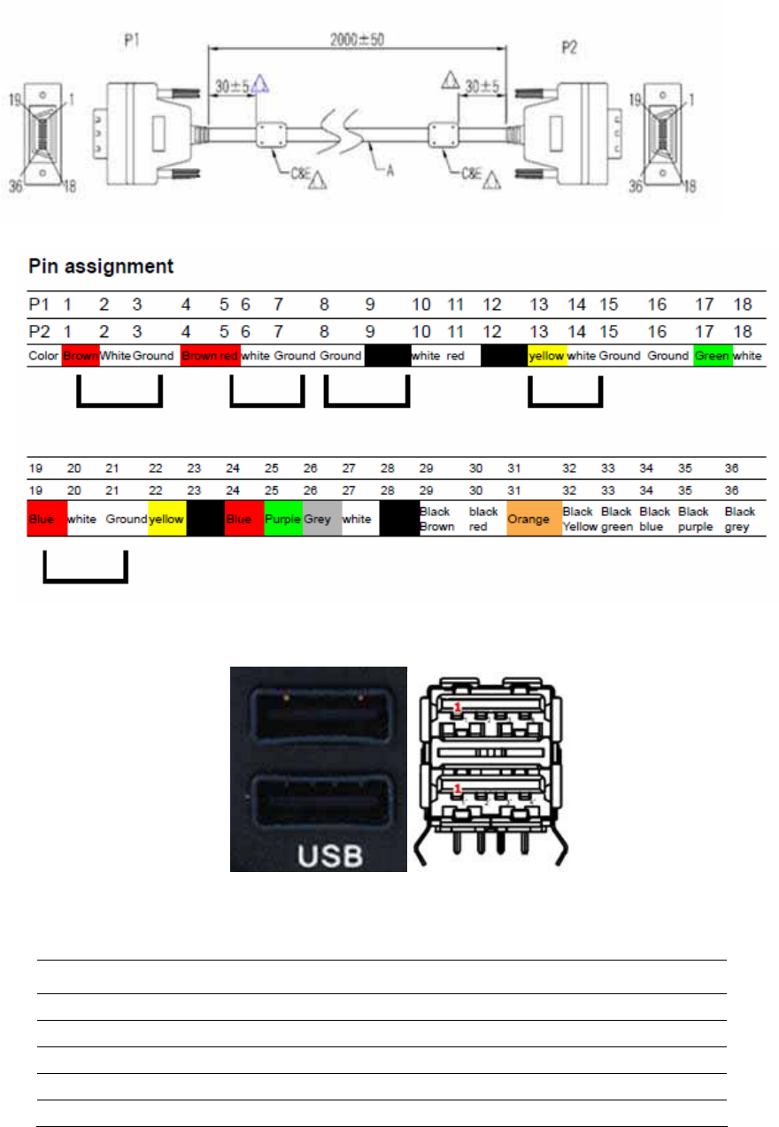
3.3.4USBConnector(Rearside)
Connector type: Stack USB A-Type Receptacle DIP UB1112C-8FDE-4F
Table 3. : USB Connector
Pin Signal Depiction
1 Vcc
2 USB_Data-
3 USB_Data+
4 GND
3.3.5USBConnector(Frontside)
TREK-688 User Manual 20
Connector type: Single USB A-Type Receptacle DIP UB1112C-4K1-4F
Table 3. : USB Connector
Pin Signal Depiction
1 Vcc
2 USB_Data-
3 USB_Data+
4 GND
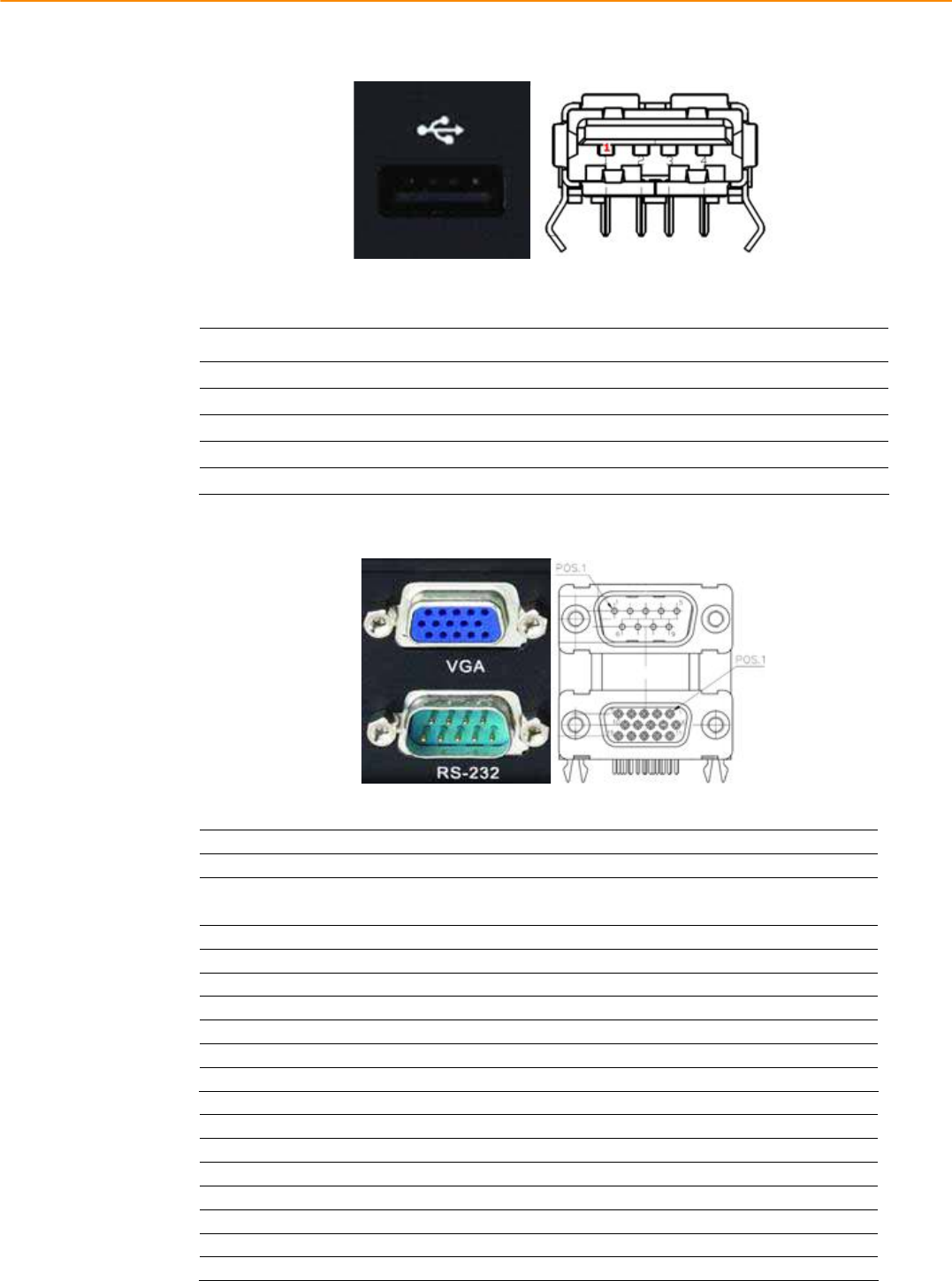
3.3.6VGA&RSͲ232Connector
Connector type: D-SUB Conn. 9P+15P 90D (M/F) DIP DM10191-H551-4F
Table3.:VGAConnector
Pin SignalDepiction Pin SignalDepiction
1 CRTR 9 CRTPOWER
+5VDC(̈́5%,max1A)
2 CRTG 10 Ground
3 CRTB 11 NC
4 NC 12 CRTDDC_DATA
5 Ground 13 CRTHSYN
6 Ground 14 CRTVSYN
7 Ground 15 CRTDDC_CLK
8 Ground
Table3.:RSͲ232Connector
Pin SignalDepiction Pin SignalDepiction
1 RSͲ232DCD 5 RSͲ232Ground
2 RSͲ232RXD 6 RSͲ232DSR
3 RSͲ232TXD 7 RSͲ232RTS
4 RSͲ232DTR 8 RSͲ232CTS
9 RSͲ232RI/+12VDCoutput
3.3.7VideoInputConnector

21 TREK-688 User Manual
Connectortype:DVIͲI29P/DVTͲI29P1.905mm
FemalerightangleDIPC1DA2G2Ͳ020ͲR
Table3.:VideoInputConnector1
Pin SignalDepiction Pin SignalDepiction
1 VideoInputChannel1 15 DigitalGround
2 VideoInputChannel2 16 DigitalGround
3 VideoInputChannel3 17 RSͲ485N
4 VideoInputChannel4 18 RSͲ485P
5 AudioInputChannel1 19 DigitalGround
6 AudioInputChannel2 20 DigitalGround
7 AudioInputChannel3 21 VideoInputChannel5
8 AudioInputChannel4 22 VideoInputChannel6
9 DigitalGround 23 VideoInputChannel7
10 DigitalGround 24 VideoInputChannel8
11 DigitalGround C1 +12VDCoutput
12 +12VDCOutputEnable# C2 +12VDCoutput
13 DigitalGround C3 +12VDCoutput
14 DigitalGround C4 +12VDCoutput
Table3.:VideoInputConnector2
Pin SignalDepiction Pin SignalDepiction
1 VideoInputChannel9 15 DigitalGround
2 VideoInputChannel10 16 DigitalGround
3 VideoInputChannel11 17 RSͲ485N
4 VideoInputChannel12 18 RSͲ485P
5 AudioInputChannel5 19 DigitalGround
6 AudioInputChannel6 20 DigitalGround
7 AudioInputChannel7 21 VideoInputChannel13
8 AudioInputChannel8 22 VideoInputChannel14
9 DigitalGround 23 VideoInputChannel15
10 DigitalGround 24 VideoInputChannel16
11 DigitalGround C1 +12VDCoutput
12 +12VDCOutputEnable# C2 +12VDCoutput
13 DigitalGround C3 +12VDCoutput
14 DigitalGround C4 +12VDCoutput
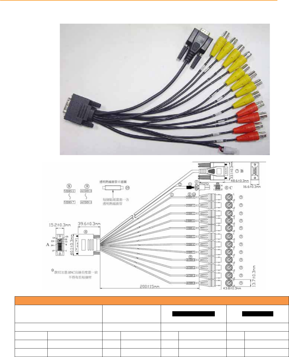
3.3.7.1VideoInputCable(P/N:1700022702Ͳ01)
TREK-688 User Manual 22
Table : Video Input Cable Connector
Pin
Depiction
HOUSING C4255HF
2*02P (PH4.2) 9P D-SUB MALE
CONNECTOR( B ) (YELLOW BNC) (RED BNC)
Power Output RS-485 VIDEO INPUT AUDIO INPUT
PIN Depiction PIN Depiction PIN Depiction PIN Depiction
1,2 +12V/2A (NC)* 1RS485-N 1VIDEO INPUT
1
AUDIO INPUT
3,4 GND (NC)* 2RS485-P 2GND
2
GND
P.S : TREK-688 doesn`t support +12V output
3.3.8VI/OConnector

23 TREK-688 User Manual
VI/OPortisTREK’snextgenerationcommunicationinterfaceconnectorwhichcontainsDualCAN
BusandSingleJ1708interface.
AllnewTREKx86computingbox(e.g.TREKͲ688,TREKͲ674)cansharethesameoneVI/Ocable.
Connector type: 15PIN D-SUB MALE CONNECTOR
Table VIO Connector Pin Assignment
Pin Signal Depiction Pin Signal Depiction
1 CAN_H 9 ODB_CAN_H_R
2 CAN_L 10 J1708_GND
3 ODB_CAN_GND 11 VIOCOM_R485P
4 J1708_DN 12 VIOCOM_422RXP
5
J1708_DP
13
VIOCOM_R485N
6
NC
14
VIOCOM_422RXN
7
CAN_GND
15
VIOCOM_232GND
8
ODB_CAN_L
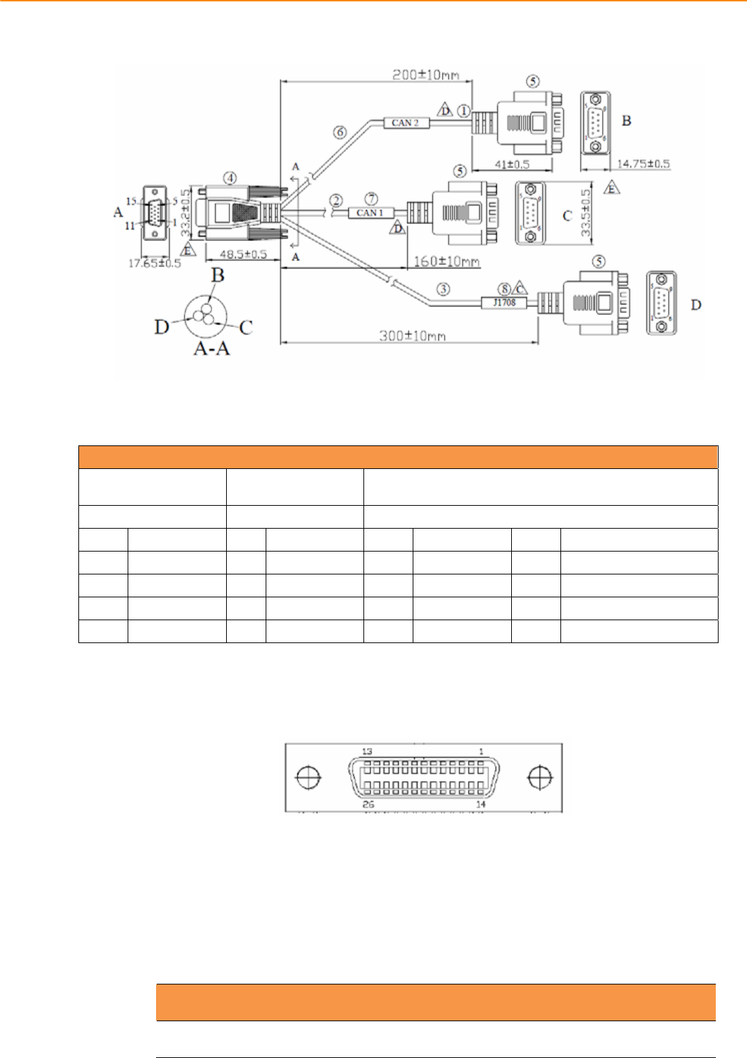
3.3.8.1VehicleI/OCable(P/N:1750023051Ͳ01)
TREK-688 User Manual 24
CONNECTOR TYPE: (D-SUB 15P MALE *1) (D-SUB 9PIN MALE*4)
Table:DB15CableConnector
Pin
Depiction
B
(DͲSUB9PINMALE)
C
(DͲSUB9PINMALE)
D
(DͲSUB9PINMALE)
CAN2BUS CAN1BUS J1708
PIN
Depiction
PIN
Depiction
PIN
Depiction
PIN
Depiction
2
CAN2_L
2
CAN1_L 1 J1708_N 2 485P/422TXP/232ͲRXD
7 CAN2_H 7 CAN1_H
4
J1708_P 6 485N/422TXP/232ͲCTS
3
CAN2_GND
3
CAN1_GND
8
J1708_GND 3 422RXP/232ͲTX
5 COMͲGND 7 422RXN/232ͲRTS
3.3.9GenericI/OConnector
GenericI/OPortisTREK’snextgenerationhighdensityconnectorwhichprovidesseveralcommonI/O
interfaceforperipheralcontrolbutitismorecompactandcosteffectivethantheHDCconnector
(a.k.a.ExtendedI/OPort)onTREKͲ688.
AllnewTREKx86computingbox(e.g.TREKͲ688,TREKͲ674)cansharethesameoneGenericI/Ocable.
However,therearesomepinassignmentdifferentonTREKͲ688andTREKͲ674.
Connector type: D-SUB Conn. 26P 1.27mm 90D(F) DIP MCR26FL33
Table GIO Connector Pin Assignment
Pin Signal Depiction Pin Signal Depiction

25 TREK-688 User Manual
1 ISO_DI1# 14 ISO_RELAYOUT1#
2 ISO_DI2# 15 ISO_RELAYOUT2#
3 ISO_DI3# 16 GIO_GND_DIO
4 ISO_DI4# 17 GIOCOMA_232_RXD
5 GIO_GND_DIO 18 GIOCOMA_232_TXD
6 ISO_RELAYOUT3# 19 GIOCOMA_232_RTS#
7 ISO_RELAYOUT4# 20 GIOCOMA_232_CTS#
8 GIO_GND_COM 21 GIO_GND_COM
9 NC 22 GIOCOMB_232_RXD
10 NC 23 GIOCOMB_232_TXD
11 GND_AUD 24 GIOCOMB_232_RTS#
12 GIO_MIC_IN 25 GIOCOMB_232_CTS#
13 GIO_LINE_OUT 26 GIO_GND_COM
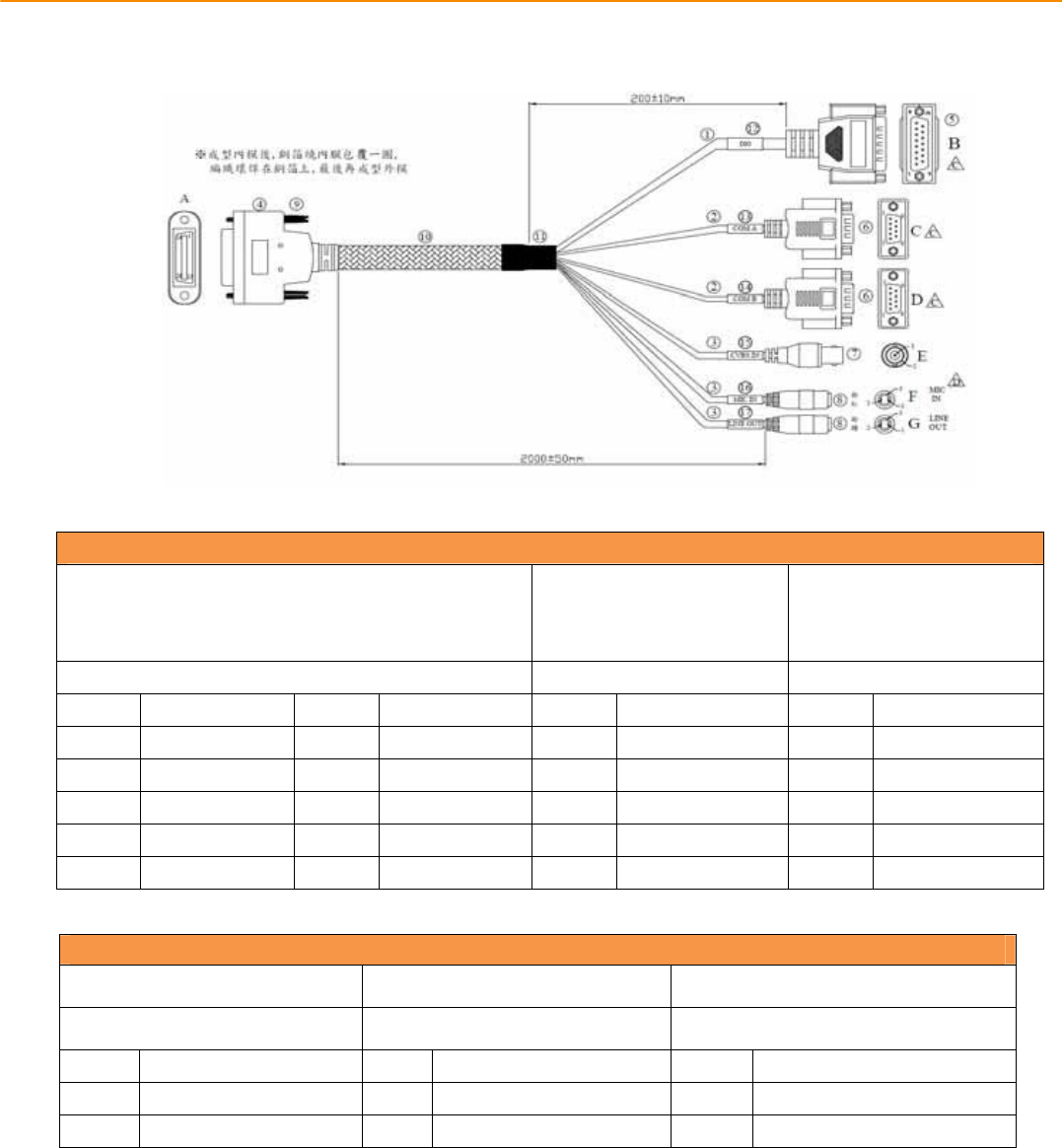
3.3.9.1GenericI/OCable(P/N:1700023050Ͳ01)
TREK-688 User Manual 26
GIOTableͲ1:C
ablePin
Depiction
15PINDͲSUBMALECONNECTOR
(B)9PINDͲSUBMALE
Connector(C) 9PINDͲSUBMALE
Connector(D)
ISO_DIO(4DI&4DO) RS232(4ͲWire) RS232(4ͲWire)
PIN
Depiction
PIN
Depiction
PIN
Depiction
PIN
Depiction
1 ISO_DI1 9 ISO_DO1 2 232ͲRXD 2 232ͲRXD
2 ISO_DI2 10 ISO_DO2 3 232ͲTXD 3 232ͲTXD
3 ISO_DI3 13 ISO_DO3 7 232ͲRTS 7 232ͲRTS
4 ISO_DI4 14 ISO_DO4 8 232ͲCTS 8 232ͲCTS
5 ISO_GND 6 ISO_GND 5 COM_GND 5 COM_GND
GIOTableͲ2:C
ablePin
Depiction
BNCJACK(E) 3.5ˠPHONEJACK(F) 3.5ˠPHONEJACK(G)
CVBSIn MIC_IN LINEOUT
PIN
Depiction
PIN
Depiction
PIN
Depiction
1 CVBSIn(NC)* 1+2 MIC_IN 1+2 LINEOUT
2 GND(NC)* 2 MIC_GND 2 AudioͲGND
P.STREKͲ688doesn`tsupportCVBSInfunction.
3.3.10LANConnector

27 TREK-688 User Manual
Chapte
r
5 Pin Assignments
Connector type: M12 A-coding Jack GT234102-01080 female 8P
Table LAN Connector Pin Assignment
Pin Signal Depiction Pin Signal Depiction
1
LAN TRP0P
5
LAN TRP2N
2
LAN TRP0N
6
LAN TRP1N
3
LAN TRP1P
7
LAN TRP3P
4
LAN TRP2P
8
LAN TRP3N

TREK-688 User Manual 28

Chapter 4
6 Software Demo Utility
Setup
This appendix explains the soft-
ware demo utility for TREK-688
Sections include:
̗ʳ
Introduction
̗ʳ
How to Set up Demo Utility
TREK-688 User Manual 30
4.1 Introduction
Advantech has developed demo utilities based on Advantech provided SDK APIs
to let user test the functions on TREK-688. This document describes the usage of
each demo utilities and also provide a basic concept of the application
development on TREK-688.
For technical support, contact Advantech application engineers worldwide. For
news updates, please visit our website : www.advantech.com and MRM forum :
http://mrmforum.advantech.com/index.aspx
4.2 IVCP Demonstration
TheIVCPdemonstrationapplicationdemonstratetheusageofMRMIVCPAPIwhichisa
lightweightinterfacebetweenOS(Operatingsystem)andIVCP(IntelligentVehicleCoͲ
Processor)allowusertoaccessthestatusofmachineandchangemachinebehaviorsuch
aspowermanagement,bootbehavior,peripheralcontroletc.
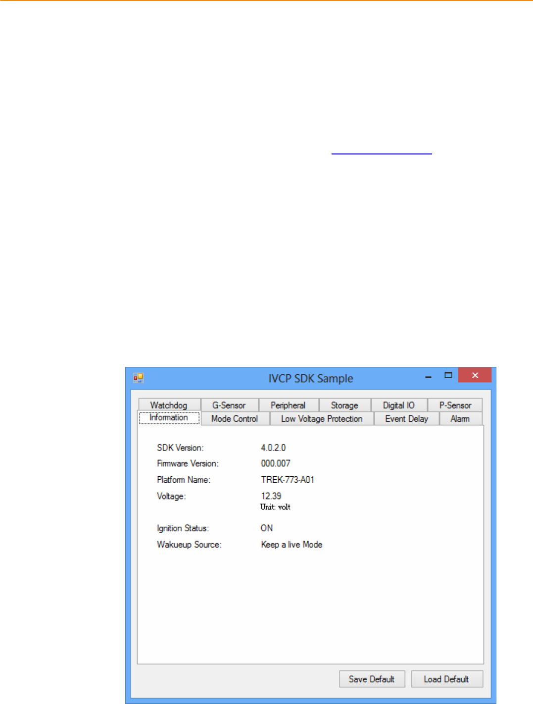
4.2.1 Information
Inthispage,thedemoapplicationshowsthecurrentstatusandbasicinformation.
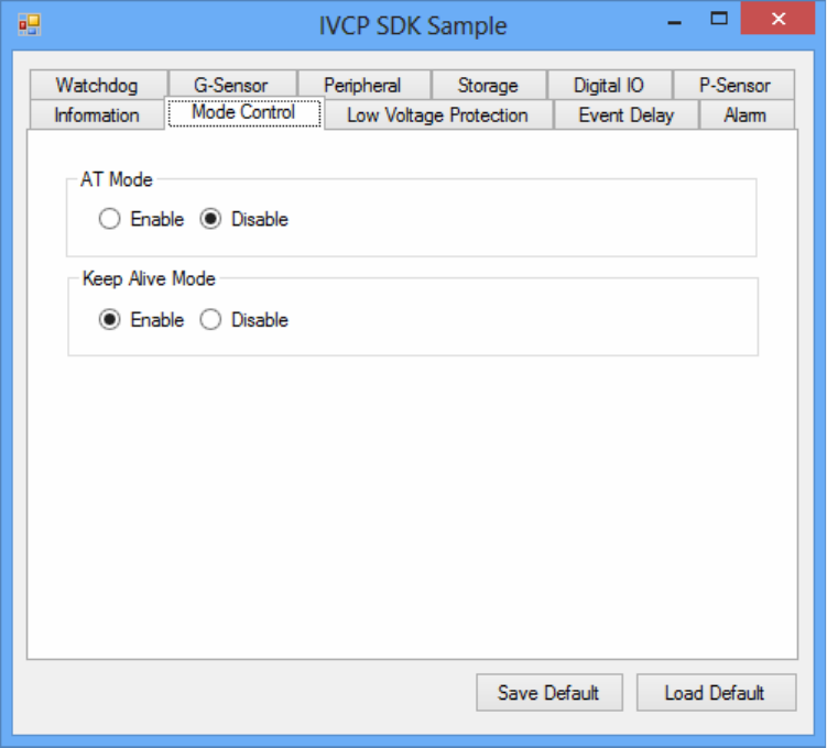
4.2.2 Mode Control
Inthispage,youcantoggle“ATMode”and“KeepAliveMode”.
Press“SaveDefault”tosetcurrentsettingsasdefaultvalueofVPM(VehiclePower
Management)controller.
Press“LoadDefault”toloadthedefaultvalues.
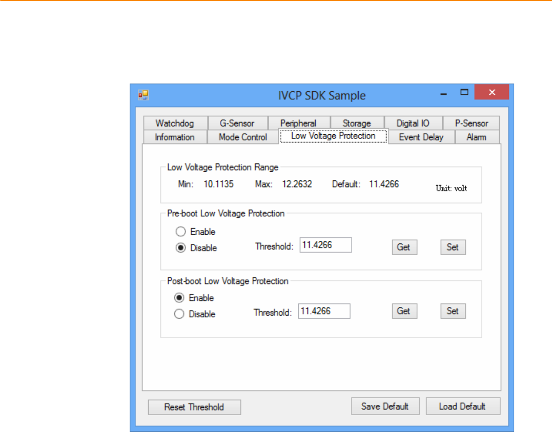
4.2.3 Low Voltage Protection
Youcanenable/disableandsetthepreͲboot/postͲbootlowvoltageprotectionthresholdin
thispage.
Press“Get”togetthecurrentthresholdvalueandPress“Set”tosetthevalue.
Press“SaveDefault”tosetcurrentvalueasdefaultvalueofVPMcontroller.
Press“LoadDefault”toloadthestoreddefaultvalues.
TREK-688 User Manual 32
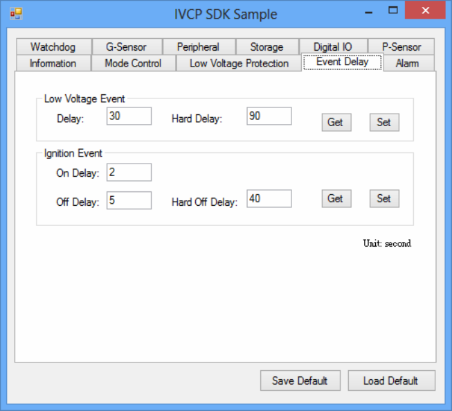
4.2.4 Event Delay
4.2.4.1 Power control mechanism
TREKͲ688providesVPM(VehiclePowerManagement)featurestofulfillspecific
requirements.Thebasicmechanismisshowninthefollowingfigure.
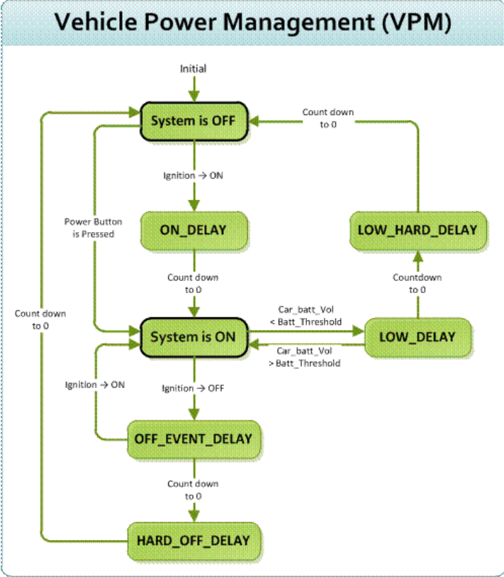
Thepowerofsystemcanbecontrolledwiththefollowingevents:
z IgnitionON
Theignitionsignalcanbeusedtopoweronorshutdownthesystem.WhenthesystemisinanOFF
stateandtheignitionisturnedON,theVPMcontrollerwillcountdownadelayperiod(ON_DELAY).
Onceitcountstozero,thesystemwillbepoweredon.
z IgnitionOFF
Whenthesystemispoweredonandtheignitionisturnedoff,theVPMcontrollerwillcountdowna
delayperiod(OFF_EVENT_DELAY).Duringthisperiod,iftheignition
isswitchedbacktoON,theVPMcontrollerwillstopcountdownandresettheOFF_EVENT_DELAY.If
OFF_EVENT_DELAYcountstozero,theVPMcontrollerwilltriggeranpoweroffevent(i.e.power
buttonpress).SystemandapplicationswhichreceivesthiseventcandopreͲdefinedtasks,likestoring
dataandpreparingtoturnoffthesystem.
Aftertheeventistriggered,VPMcontrollerstartstocountdownnextdelayperiod(HARD_OFF_DELAY).
IfHARD_OFF_DELAYcountstozero,thesystempowerwillbecutoffabruptlytoavoidunexpected

TREK-688 User Manual 34
systemhang.Aldo,onceVPMcontrollerentertheHARD_OFF_DELAYstage,theprocesscannotbe
reversed.
z Lowpowerprotection
Toavoiddrainingpower,lowͲpowerprotectionistoensurethatthereisenoughpower
tostartthemachine.WhenthesystemisON,theVPMcontrollerwillmonitorthepowervoltage.If
thevoltageislowerthantheprogrammablethreshold(LOW_THRESHOLD),theVPMcontrollerwill
starttocountdownadelay(LOW_DELAY).DuringthestageofLOW_DELAYcountdown,ifvoltage
goesbackaboveLOW_THRESHOLD,theVPMcontrollerwillstopcounting
downandexit.
IfLOW_DELAYcountstozero,theVPMcontrollerwilltriggeranpoweroffevent(i.e.powerbutton
press)andstartstocountdownnextdelayperiod(LOW_HARD_DELAY).IfLOW_HARD_DELAYcounts
tozero,thesystempowerwillbecutoffabruptlytoavoiddrainingthepower.
4.2.4.2 Demonstration
Youcansetthedelayandharddelaytimeofthelowvoltageeventandignitionevent.
LowVoltageEvent
z Delay:
ThedelaytimebeforeVPMtriggerapoweroffevent(i.e.powerbuttonpress).
z HardDelay:
Thedelaytimecounteddownafterapoweroffeventistriggered.VPMwillforcepoweroffthe
machineiftheharddelaytimeiscounteddowntozero.
IgnitionEvent
z OnDelay:
ThedelaytimebeforeVPMtriggeranpoweronevent(poweronthemachine).
z OffDelay:
ThedelaytimebeforeVPMtriggeranpoweroffevent(i.e.powerbuttonpress).
z HardOffDelay:
Thedelaytimecountedafteranpoweroffeventistriggered.VPMwillforcepoweroffthe
machineiftheharddelaytimeiscounteddowntozero.
Press“SaveDefault”tosetcurrentvalueasdefaultvalue.
Press“LoadDefault”toloadthestoreddefaultvalues.
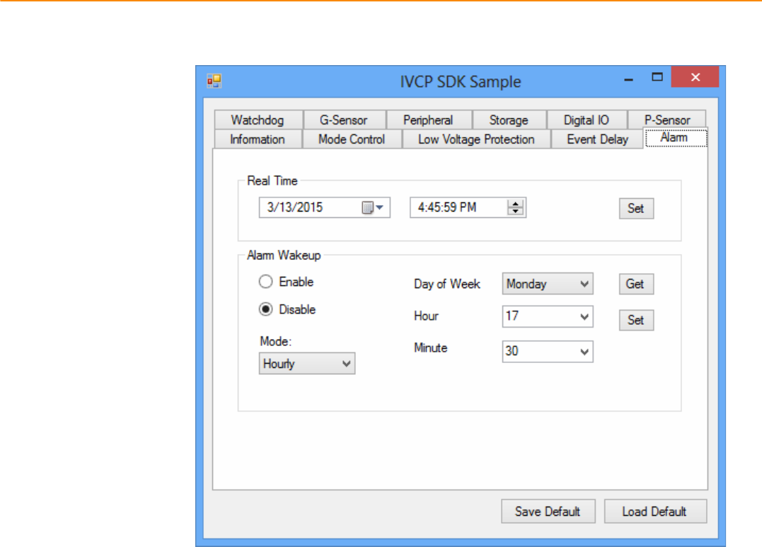
4.2.5 Alarm
Inthispage,youcansetthetimeandsetalarmwakeuptimetoVPMcontrollerandenable/disablethe
alarmasasystemwakeupsource.
Press“SaveDefault”tosetcurrentvalueasdefaultvalue.
Press“LoadDefault”toloadthestoreddefaultvalues.
TREK-688 User Manual 36
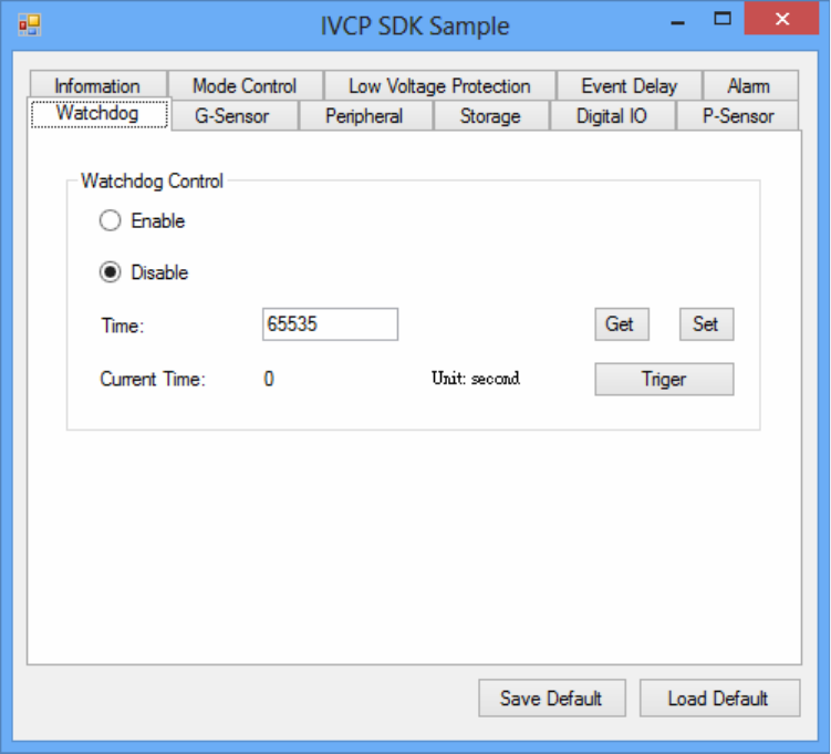
4.2.6 Watchdog
Inthispage,youcanenable/disablethewatchdogfunctionandsetthecounttime(second)forthe
watchdogtoavoidunexpectedsystemhang..
Whenwatchdogisenabled,theVPMcontrollerwillstartcountingdownthetimesetforwatchdogand
poweroffthemachineifitiscountedto0.Youcanpress“Trigger”buttonwhilewatchdogiscounting
toresetthecountdowntimeandkeepitcounting.
Press“SaveDefault”tosetcurrentvalueasdefaultvalue.
Press“LoadDefault”toloadthestoreddefaultvalues.
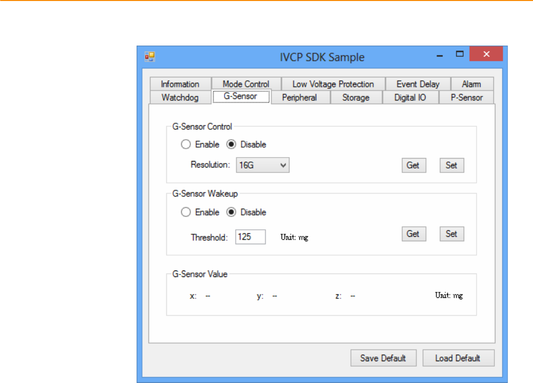
4.2.7 G-Sensor
Inthispage,youcanenable/disabletheGͲsensor.Also,youcansetGͲsensorasasystemwakeup
sourceandsetthethresholdtotriggersystemwakeup.
TREK-688 User Manual 38
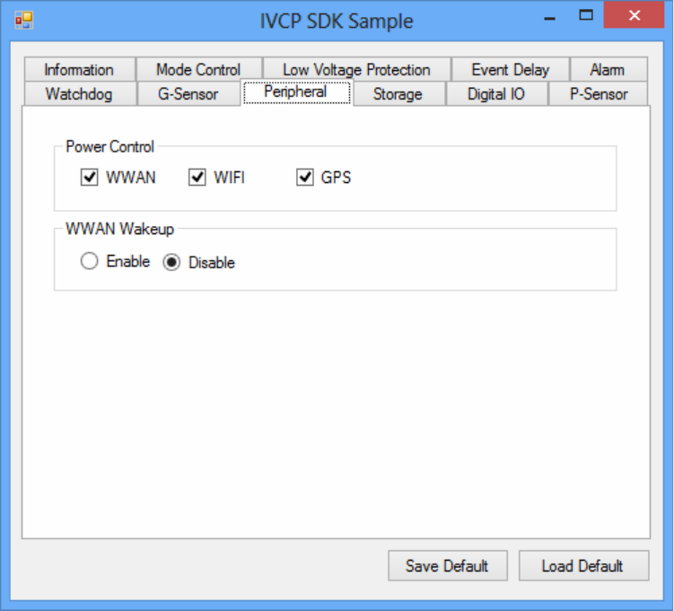
4.2.8 Peripheral
Inthispage,youcanenable/disabletheperipheralfunctionsandsetWWANassystemwakeupsource.
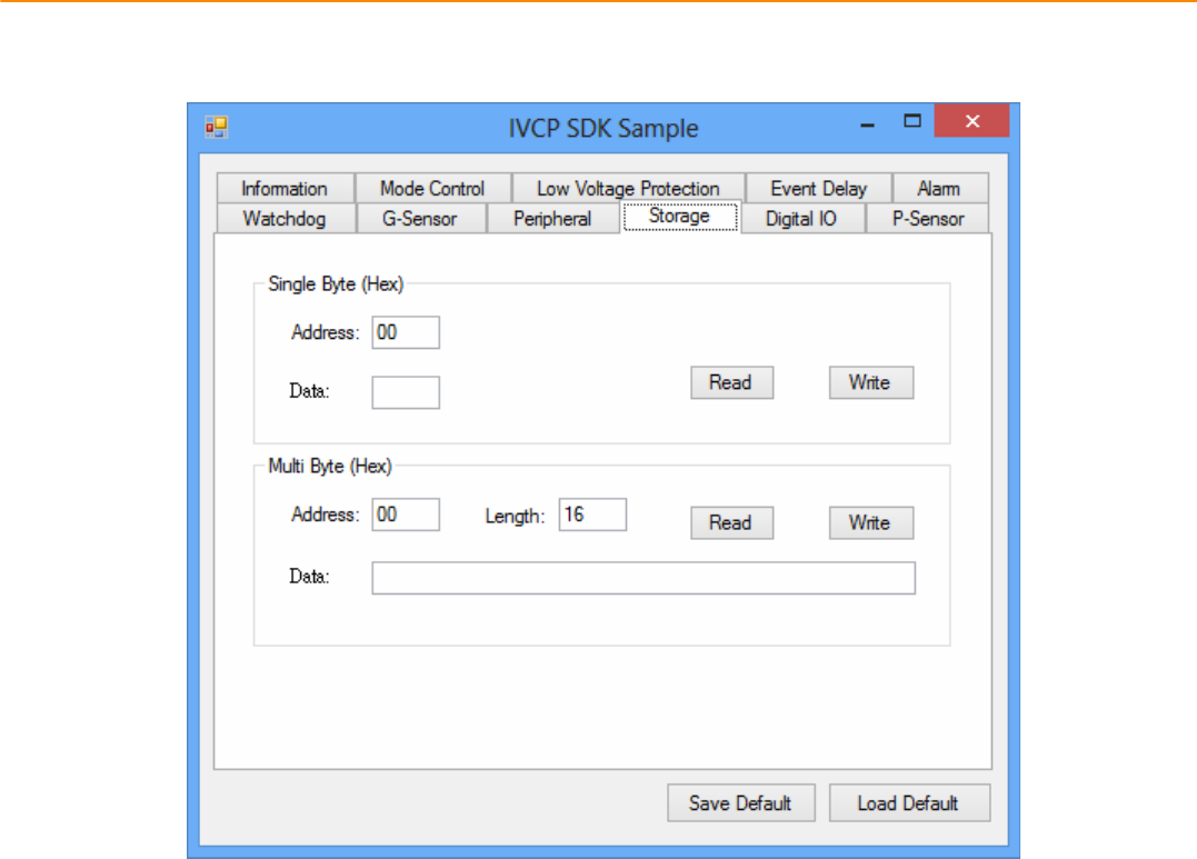
4.2.9Storage
Inthispage,youcansave/loadarbitrarydatatotheprivatestorage(256byte)onthemachine.
TREK-688 User Manual 40
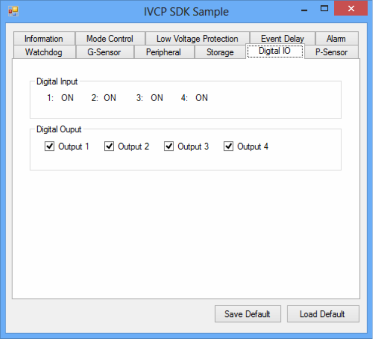
4.2.10 Digital I/O
Inthispage,youcanmonitorthedigitalinputstatusandenable/disabledigitaloutput.
DI1defaultisnormaldigitalinputandcanbesetasdedicatedreversesignalinput.
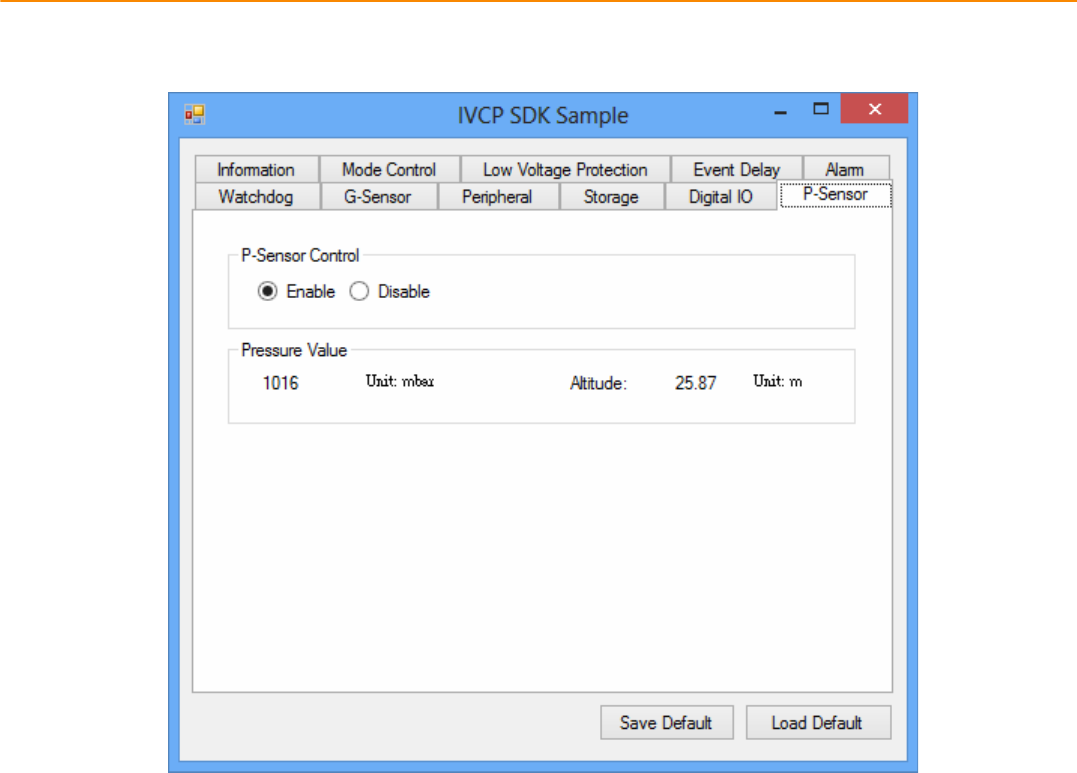
4.2.11 P-Sensor
Inthispage,youcanmonitorthepͲsensorstatusandenable/disableit.
TREK-688 User Manual 42
4.3 VCIL Demonstration
TheVCILdemonstrationapplicationdemonstratetheusageofMRMVCIL(Vehicle
CommunicationInterfaceLayer)APIwhichallowusertoaccessvehicleprotocoleasily.
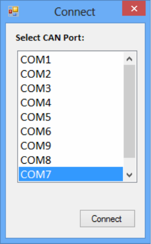
4.3.1 Port selection
WhenfirstopenVCILdemonstrationapp,youwillseeaportselectionwindowsasfollowing.
PleaseselecttheVCILportpathandpressConnectbutton.
VCILportpathindifferentplatformshavedifferentnodes.ThecommonpathatWindowisCOM7.
TREK-688 User Manual 44
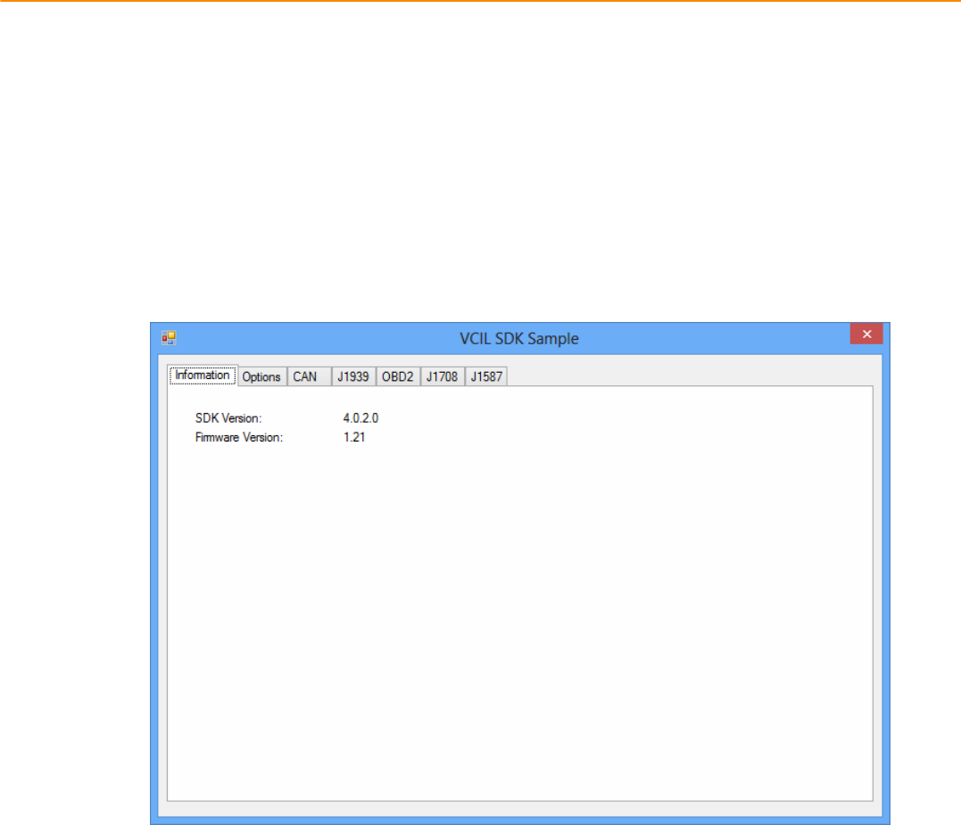
4.3.2 Information
Inthispage,thedemoapplicationshowsthecurrentstatusandbasicinformation.
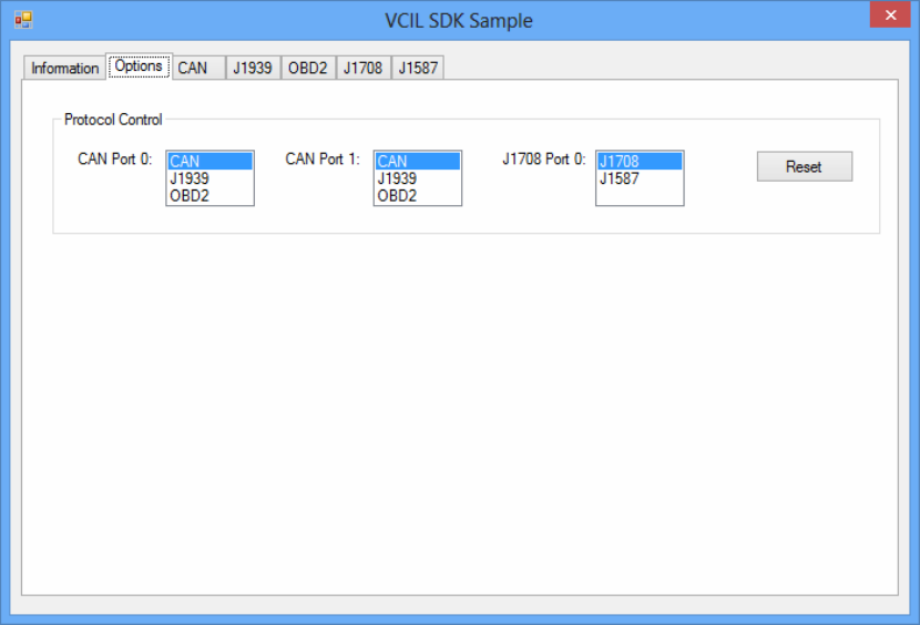
4.3.3 Option
Inthispage,youcanthesettheprotocolforeachport.
TREK-688 User Manual 46
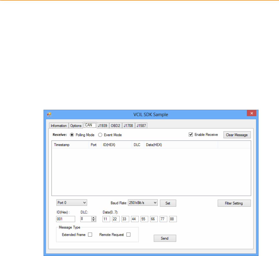
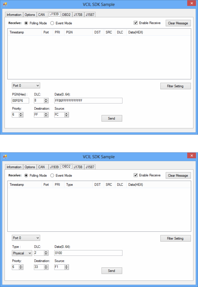
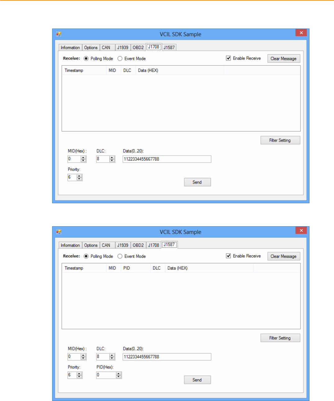
4.3.4 CAN / J1939 / OBD2 / J1708 / J1587
TouseCAN/J1939/OBD2/J1708/J1587protocoloneachport,pleaseclickoncorrespondingtabto
switchtothepageofspecificprotocol,thenyoucansend/readmessageonspecificportbysettingthe
detailitems.
TREK-688 User Manual 48
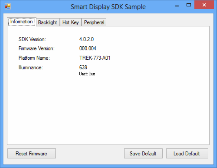
4.4SmartDisplayDemonstration
ThesmartdisplaydemonstrationapplicationdemonstratetheusageofMRMSDPAPIwhichisa
lightweightinterfacebetweenOS(Operatingsystem)andSDP(SmartDisplayCoͲProcessor)allowuser
tocontrolthefontͲenddisplay,backlightsetting,hotkey,peripheralcontrol,etc.
4.4.1 Information
Inthispage,thedemoapplicationshowsthecurrentstatusandbasicinformation.
TREK-688 User Manual 50
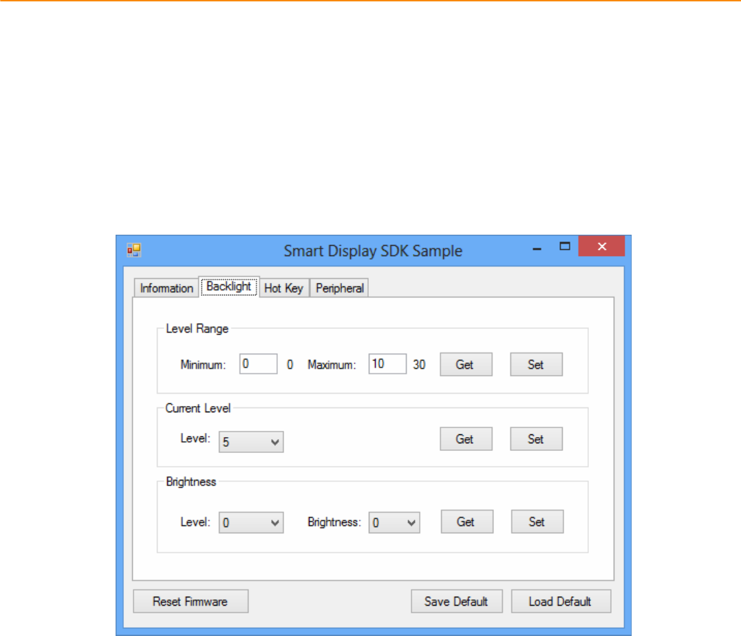
4.4.2 Backlight
Inthispage,youcansetthelevelsforbacklight,thebrightnessforeachlevelandthecurrent
brightnesslevel.
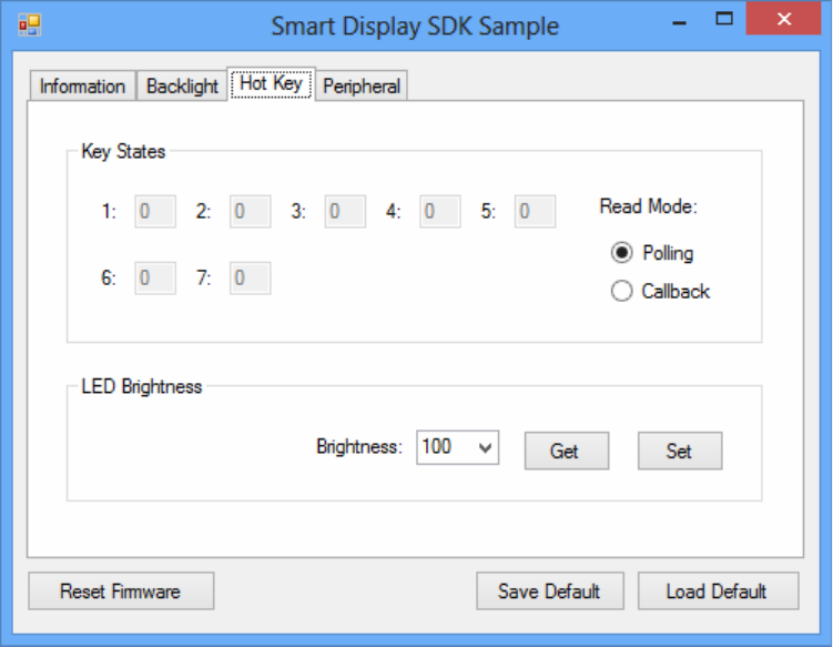
4.4.3 Hot key
Inthispage,youcanmonitorthepressstateofeachhotkeyandsettheLEDbrightnessofthehotkeys.
TREK-688 User Manual 52
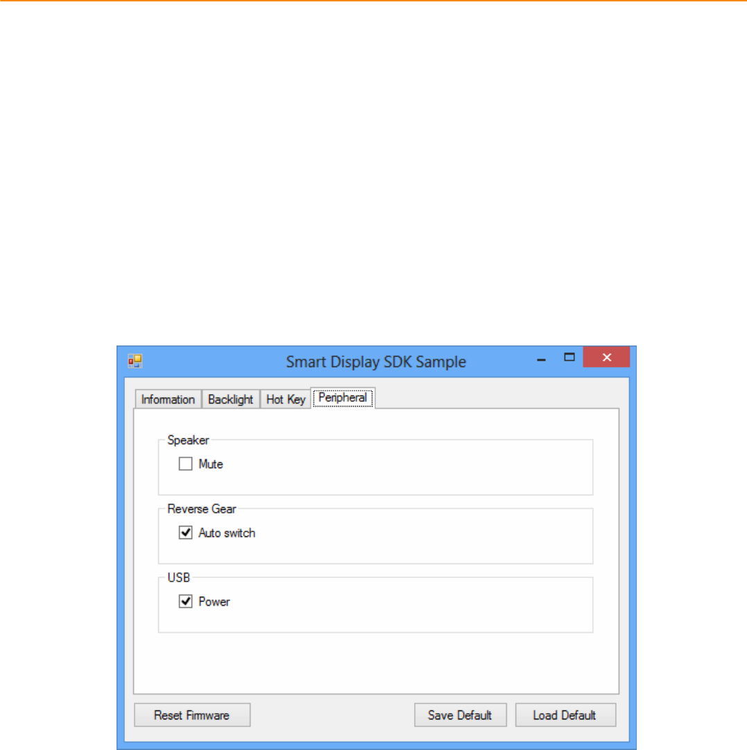
4.4.4 Peripheral
Inthispage,youcancontrolthestatusofperipheraldevices.
z Speaker
Enable/disablespeakervolume.
z Reservegear
Enable/disableautoswitchofdisplay.Ifenabled,thedisplaywillbeswitchedtocameraviewif
reversegeardetectedandswitchedtoLVDSviewifreversegearabsent.
z USB
Enable/disablepoweroffrontͲendUSBport.
4.5GPSDemonstration
TheGPSdemonstrationapplicationdemonstratetheusageofMRMGPSAPIwhichisalightweight
interfacebetweenOS(Operatingsystem)andGPSmoduleallowsusertoeasilygetGPSinformation.
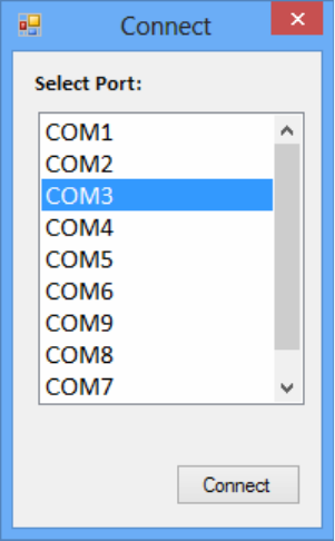
4.5.1 Port selection
WhenfirstopenGPSdemonstrationapp,youwillseeaportselectionwindowsasfollowing.
PleaseselecttheGPSportpathandpressConnectbutton.ThecommonpathatWindowisCOM3.
TREK-688 User Manual 54
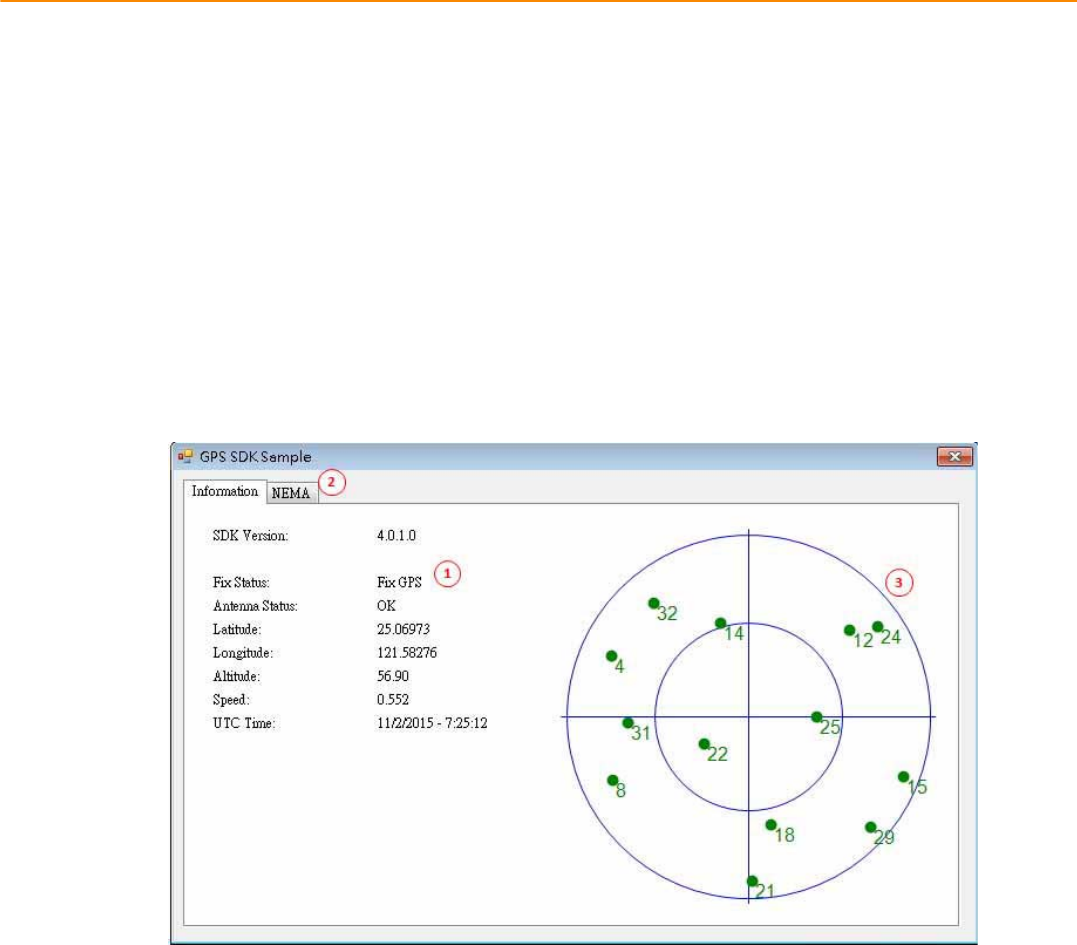
4.5.2 Information
Inthispage,thedemoapplicationshowsthecurrentGPSstatus.
1. GPSStatus
2. Functiondemonstrationselection
3. SatellitelocationInformation
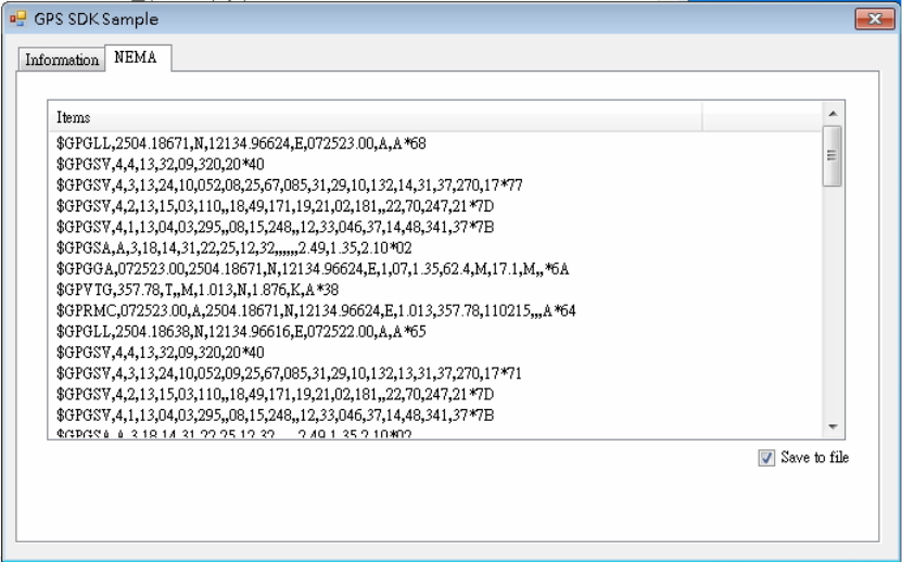
4.5.3 NEMA
Inthispage,thedemoapplicationshowstheincomingNMEAcode.Check'Savetofile'tologgingthe
NMEAcodetofile.

www.advantech.com
Please verify specifications before quoting. This guide is intended for reference
purposes only.
All product specifications are subject to change without notice.
No part of this publication may be reproduced in any form or by any means,
electronic, photocopying, recording or otherwise, without prior written permis-
sion of the publisher.
All brand and product names are trademarks or registered trademarks of their
respective companies.
© Advantech Co., Ltd. 2010