Advantech Data Acquisition Modules Adam 4000 Users Manual
ADAM 4000 to the manual 3bbbceb2-10c6-4f24-8f7c-b05ba99ff31c
2015-02-02
: Advantech Advantech-Data-Acquisition-Modules-Adam-4000-Users-Manual-413091 advantech-data-acquisition-modules-adam-4000-users-manual-413091 advantech pdf
Open the PDF directly: View PDF ![]() .
.
Page Count: 429 [warning: Documents this large are best viewed by clicking the View PDF Link!]
ADAM 4000
Data Acquisition Modules
User's Manual
ADAM 4000 Series
Data Acquisition Modules
User’s Manual
Copyright Notice
This document is copyrighted, 1997, by Advantech Co., Ltd. All rights are
reserved. Advantech Co., Ltd., reserves the right to make improvements to the
products described in this manual at any time without notice.
No part of this manual may be reproduced, copied, translated or transmitted in
any form or by any means without the prior written permission of Advantech Co.,
Ltd. Information provided in this manual is intended to be accurate and reliable.
However, Advantech Co., Ltd. assumes no responsibility for its use, nor for any
infringements upon the rights of third parties, which may result from its use.
CE Notification
The ADAM-4000 series developed by Advantech Co., Ltd. has passed the CE
test for environmental specifications when operated within an industrial enclosure
(ADAM-4950-ENC). Therefore, in order to protect the ADAM modules from
being damaged by ESD (Electric Static Discharge), we strongly recommend that
the use of CE-compliant industrial enclosure products when using any ADAM
module.
Acknowledgments
ADAM is a trademark of Advantech Co., Ltd.
IBM and PC are trademarks of International Business
Machines Corporation.
Edition 10.7
May 2008
Table of Contents
Chapter 1 Introduction ..….....……..................…..................…….. 1-1
1.1 Overview .......................…................................….........….…… 1-2
1.2 Applications ..................….........................…….............…....... 1-4
Chapter 2 Installation Guideline ...................….................…....... 2-1
2.1 System Requirements to set up an ADAM network ..…....... 2-2
2.2 Basic configuration and hook-up ....................……............... 2-6
2.3 Baud rate and Checksum .................................……............... 2-9
2.4 Multiple Module Hookup ...............................………............... 2-11
2.5 Programming Example.....................................……................ 2-12
Chapter 3 I/O Modules ..................................................…............. 3-1
3.1 ADAM-4011/4011D Thermocouple Input Modules ...…......... 3-3
3.2 ADAM-4012 Analog Input Module ………………..…............... 3-10
3.3 ADAM-4013 RTD Input Modules .......………………….…….... 3-15
3.4 ADAM-4015 6-channel RTD Input Module .…………….......... 3-17
3.5 ADAM-4015T 6-channel Thermistor Input Module ....…........ 3-20
3.6 ADAM-4016 Analog Input/Output Module....………….…....... 3-22
3.7 ADAM-4017/4017+/4018/4018M/4018+ 8-channel Analog Input
Modules ........……………………………………………………..... 3-27
3.8 ADAM-4019+ 8-channel Universal Analog Input
Module ..................................................................................... 3-37
3.9 ADAM-4021 Analog Output Module ........................…........... 3-41
3.10 ADAM-4024 4-channel Analog Output Module ................... 3-44
3.11 ADAM-4050 Digital I/O Module ……………………………..... 3-47
3.12 ADAM-4051 16-channel Isolated Digital Input Module ..…. 3-49
3.13 ADAM-4052 Isolated Digital Input Module ……………..…... 3-51
3.14 ADAM-4053 16-channel Digital Input Module …..……..…... 3-53
3.15 ADAM-4055 16-channel Isolated Digital I/O Module ……... 3-56
3.16 ADAM-4056S 12-channel Sink Type Isolated Digital Output
Module …………………………………………………….……..... 3-61
3.17 ADAM-4056SO 12-ch. Source Type Isolated Digital Output
Module ………….…………………………………………..……... 3-63
3.18 ADAM-4060/4068 Relay Output Module ................…........... 3-65
3.19 ADAM-4069 8-channel Relay Output Module ………………. 3-69
3.20 ADAM-4080/4080D Counter/Frequency Input Modules ….. 3-72
Chapter 4 Command Set ..................................................…......... 4-1
4.1 Introduction.................................................................….......... 4-2
4.2 Syntax .........................................................................….......... 4-2
4.3 I/O Module Commands Search Table ......................….......... 4-4
Chapter 5 Analog Input Module Command Set ........….............. 5-1
5.1 Analog Input Command Set ................................……............ 5-2
5.2 Analog Input Data Logger Command Set ............….…......... 5-34
5.3 Digital I/O, Alarm and Event Command Set ......………......... 5-47
5.4 Excitation Voltage Output Command Set ............…….......... 5-61
Chapter 6 AO commands..................................................…......... 6-1
6.1 Analog Output Module Command for ADAM-4021…............ 6-2
6.2 Analog Output Module Command for ADAM-4024...…......... 6-19
Chapter 7 Digital IO, Relay & Counter commands.........…......... 7-1
7.1 Configuration, Counter Input and Display Command Set ... 7-2
7.2 Counter/Frequency Module Command.................................. 7-28
7.2.1 Configuration, Counter Input and Display Command Set…... 7-28
7.2.2 Counter Setup Command Set................................................... 7-40
7.2.3 Digital Filter and Programmable Threshold Command Set….7-49
7.2.4 Digital Output and Alarm Command Set.................................. 7-60
Chapter 8 Calibration ...........................................…..................... 8-1
8.1 Analog Input Module Calibration ............................…........... 8-2
8.2 Analog Input Resistance Calibration .................................... 8-5
8.3 Analog Input Thermistor module Calibration ....................… 8-7
8.4 Analog Output Calibration ..................................................... 8-13
Appendix A Technical Specifications..............................…......... A-1
A.1 ADAM-4011 Thermocouple Input Module ................…......... A-2
A.2 ADAM-4011D Thermocouple Input Module with LED
Display .......................................................................……...... A-5
A.3 ADAM-4012 Analog Input Module ......................................... A-8
A.4 ADAM-4013 RTD Input Module ......................................….... A-10
A.5 ADAM-4016 Strain Gauge Input Module .....................…...... A-12
A.6 ADAM-4017/4017+ 8-Channel Analog Input Module ..…..... A-14
A.7 ADAM-4018/4018+ 8-channel Analog Input Module ...…..... A-16
A.8 ADAM-4018M 8-channel Analog Input Data Logger ....…... A-19
A.9 ADAM-4019+ 8-channel Universal Analog Input Module A-22
A.10 ADAM-4021/4024 Analog Output Module ........................... A-24
A.11 ADAM-4050 Digital I/O Module.................................…......... A-28
A.12 ADAM-4051/4052 Isolated Digital Input Module ................. A-30
A.13 ADAM-4053 16-channel Digital Input Module ............…..... A-32
A.14 ADAM-4055 16-channel Digital I/O Module ............…......... A-34
A.15 ADAM-4056S 12-channel Sink Type Isolated Digital Output
Module .......…………………………………………………...….. A-36
A.16 ADAM-4056SO 12-channel Source Type Isolated Digital Output
Module ........……………………………………………….…...... A-38
A.17 ADAM-4060 Relay Output Module........................................ A-40
A.18 ADAM-4068/4069 8-channel Relay Output Module ............ A-42
A.19 ADAM-4080 Counter/Frequency Input Module ................... A-44
A.20 ADAM-4080D Counter/Frequency Input Module with LED
Display …................................................................................ A-46
Appendix B Data Formats and I/O Ranges ..................…............ B-1
B.1 Analog Input Formats.............................................…............. B-2
B.1.1 Engineering Units .............................................................…….......... B-2
B.1.2 Percent of FSR .................................................................…............. B-3
B.1.3 Twos complement hexadecimal .....................................……............ B-4
B.1.4 Ohms ..............................................................................……............ B-5
B.2 Analog Input Ranges.............................................….............. B-6
B.3 Analog Output Formats ..............................................…........ B-11
B.3.1 Engineering Units ............................................................………........ B-11
B.3.2 Percent of Span ........................................................…….................. B-11
B.3.3 Hexadecimal ............................................................………............... B-11
B.4 Analog Output Ranges .......................................…................ B-12
Appendix C Technical Diagrams .................................…............. C-1
C.1 ADAM Dimensions ..............................................…................ C-2
C.2 Installation .............................................................….............. C-3
C.2.1 DIN-Rail Mounting ......................................................…...….............. C-3
C.2.2 Panel Mounting .............................................................…….............. C-5
C.2.3 Piggyback Stack ....................................................….....…................. C-7
Appendix D Utility Software .................................…..................... D-1
D.1 ADAM-4000 Utility Software ......................…......................... D-2
D.2 The procedure for ADAM-4000 series installation guide…..D-6
Appendix E RS-485 Network .............................…........................ E-1
E.1 Basic Network Layout ................................…......................... E-3
E.2 Line Termination .........................................…........................ E-5
E.3 RS-485 Data Flow Control ..................................................... E-7
Appendix F How to use the Checksum feature ..........…............ F-1
F.1 Checksum Enable/Disable ......................................…............ F-2
Appendix G ADAM-4000 I/O Modbus Mapping Table ....…......... G-1
Appendix H Changing Configuration to Modbus Protocol ....... H-1
Introduction 1

Introduction
1-
2
ADAM 4000 Series User’s Manual
1.1 Overview
The ADAM Series is a set of intelligent sensor-to-computer
interface modules containing built-in microprocessor. They are
remotely controlled through a simple set of commands issued in ASCII
format and transmitted in RS-485 protocol. They provide signal
conditioning, isolation, ranging, A/D and D/A conversion, data
comparison, and digital communication functions. Some modules
provide digital I/O lines for controlling relays and TTL devices.
Software Configuration and Calibration
By merely issuing a command from the host computer, you can
change an analog input module to accept several ranges of voltage input,
thermocouple input or RTD input. All of the module’s configuration
parameters including I/O address, communication speed, HI and LO
alarm, calibration parameters settings may be set remotely. Remote
configuration can be done by using either the provided menu-based
software or the command set’s configuration and calibration commands.
By storing configuration and calibration parameters in a nonvolatile
EEPROM, modules are able to retain these parameters in case of power
failure.
Watchdog Timer
A watchdog timer supervisory function will automatically reset the
ADAM modules in the event of system failure. Maintenance is thus
simplified.
Power Requirements
Although the modules are designed for standard industrial
unregulated 24 VDC power supply, they accept any power unit that
supplies power within the range of +10 to +30 VDC. The power supply
ripple must be limited to 5 V peak-to-peak, and the immediate ripple
voltage should be maintained between +10 and +30 VDC.
Connectivity and Programming
ADAM modules can connect to and communicate with all computers
and terminals. They use RS-485 transmission standards, and
communicate with ASCII format commands. The command set for
every module type consists of approximately ten different commands.
Chapter 1
Chapter 1 Introduction 1
-3
The command set for input modules is larger because it incorporates
alarm functions. All communications to and from the module are
performed in ASCII, which means that ADAM modules can be
virtually programmed in any high-level language.
RS-485 Network
The RS-485 network provides lower-noise sensor readings, as
modules can be placed much closer to the source. Up to 256 ADAM
modules may be connected to an RS-485 multi-drop network by using
the ADAM RS-485 repeater which extends the maximum
communication distance up to 4,000 ft. The host computer is connected
to the RS-485 network with one of its COM ports through the ADAM-
452x module (RS-232 to RS-422/485 converter).
To boost the network’s throughput, ADAM RS-485 repeater uses a
logical RTS signal to manage the repeater’s direction. The only two
wires that are needed for the RS-485 network, DATA+ and DATA-, are
inexpensive shielded twisted pair.
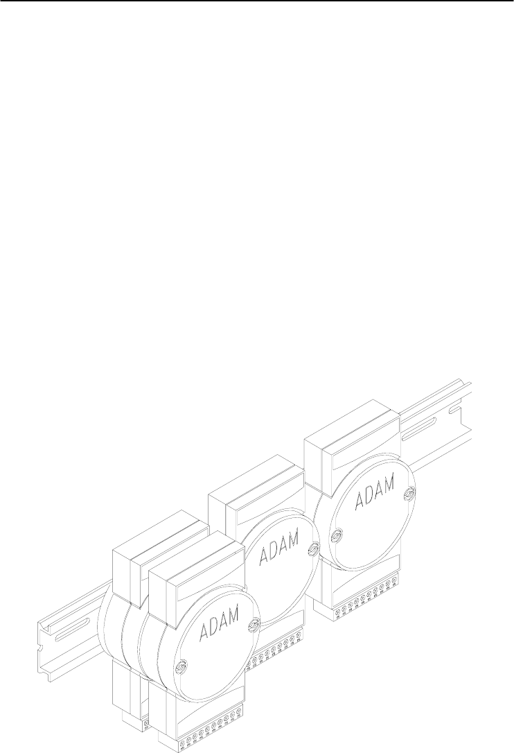
Panel/DIN Rail mounting

Introduction
1-
4
ADAM 4000 Series User’s Manual
ADAM modules can be mounted on any panels, brackets, or DIN
rails. They can also be stacked together.
The RS-485 network, together with screw-terminal plug connectors,
allows for system expansion, reconfiguration, and repair without
disturbing field wiring.
Protection against the environment
Since all the configurations are controlled by software, the
protection provided by the packaging is very important. The plastic
outer shell enhances resistance against corrosive materials, moistures
and vibrations. ADAM modules’ low power requirements help them to
operate in temperatures from 0 to 70 ℃, and in humidity from 0 to 95%
(non-condensing). They are compactly built using automated SMT
technology. Therefore, they can be implemented in water-tight and
explosion-proof industrial enclosures.
1.2 Applications
• Remote data acquisition
• Process monitoring
• Industrial process control
• Energy management
• Supervisory control
• Security systems
• Laboratory automation
• Building automation
• Product testing
• Direct digital control
Installation Guideline 2

Installation Guideline
2-
2
ADAM 4000 Series User’s Manual
This chapter provides guidelines to what is needed to set up and
install an ADAM network. A quick hookup scheme is provided that lets
you configure modules before they are installed in a network. To help
you connect ADAM modules with sensor inputs, several wiring
examples are provided. At last, you will find a programming example
using the ADAM command set at the end of this chapter.
Be sure to plan the layout and configuration of your network
carefully before you start. Guidelines regarding layout are given in
Appendix E: RS-485 Network.
2.1 System Requirements to set up an ADAM network
The following list gives an overview of what is needed to setup,
install and configure an ADAM environment.
• ADAM modules
• A host computer, such as an IBM PC/AT compatible, that can
output ASCII characters with a RS-232C or RS-485 port.
• Power supply for the ADAM modules (+10 to +30 VDC )
• ADAM Series Utility software
• ADAM Isolated RS-232/RS-485 Converter (optional)
• RS-232/RS-485 ADAM Repeater (optional)
Host computer
Any computer or terminal that can output in ASCII format over
either RS-232 or RS-485 can be connected as the host computer. When
only RS-232 is available, an ADAM RS-232/RS-485 Converter is
required to transform the host signals to the correct RS-485 protocol.
The converter also provides opto-isolation and transformer-based
isolation to protect your equipment.

Chapter 2
Chapter 2 installation Guideline 2
-3
Power supply
For the ease of use in industrial environments, the ADAM modules
are designed to accept industry standard +24 VDC, unregulated power.
Operation is guaranteed when using any power supply between +10 and
+30 VDC . Power ripples must be limited to 5 V peak to peak while the
voltage in all cases must be maintained between +10 and +30 VDC . All
power supply specifications are referenced at module connector. When
modules are powered remotely, the effects of DC voltage drops must be
considered.
All modules use on-board switching regulators to sustain good
efficiency over the 10 to 30 V input range; therefore, we can assume
that the actual drawn current is inversely proportional to the DC voltage.
The following example shows how to calculate the required current that
a power supply should provide.
Assume that a +24 VDC is used for five ADAM-4011 Analog Input
Modules, and the distance between modules and power supply is not
significant enough to cause a DC voltage drop. One ADAM-4011
module consumes a maximum of 1.2 Watts (W). The total required
power will equal to 5 x 1.2=6 W. A power supply of +24 VDC should
therefore be able to supply a minimal current of 6 / 24=0.25 Amps.
Small systems may be powered by using wall-mounted modular
power supplies. Also, when modules operate in long communication
lines (>500 feet), it is often more reliable to obtain power locally
through modular power supplies. These inexpensive units can be easily
obtained from any electronic retail stores.
The power cables should be selected according to the length of the
power lines and the number of modules connected. When implementing
a network with long cables, the use of thicker wire is more suitable due
to the limitation of DC voltage drop. Furthermore, long wires can also
cause interference with communication wires.
Installation Guideline
2-
4
ADAM 4000 Series User’s Manual
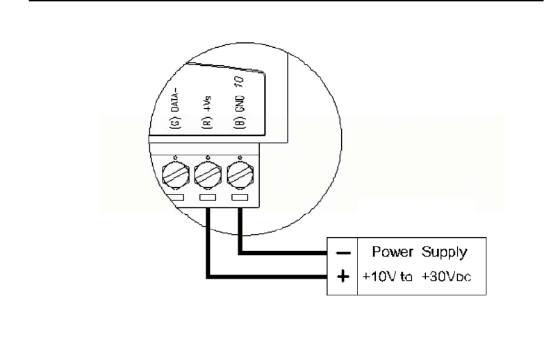
Figure 2-1 Power Supply Connections
We advise the following standard colors (as indicated on the
modules) for each power line:
+Vs (R) Red
GND (B) Black
Communication Wiring
We recommend the use of shielded-twisted-pair cable in the ADAM
network for reducing interference purpose, but the cable has to comply
with the EIA RS-485 standard. Furthermore, only one set of twisted-
pair cable is required for transmitting Data. We advise the following
standard colors (as indicated on the modules) for each the
communication line:
DATA+ (Y) Yellow
DATA- (G) Green
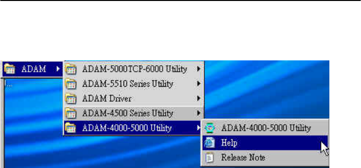
ADAM Utility Software
A menu-driven utility program is provided for ADAM module
configuration, monitoring and, calibration. It also includes a terminal
emulation program that lets you communicate through the ADAM
command set. (See Appendix D, Utility Software and online help)
Chapter 2
Chapter 2 installation Guideline 2
-5
Notice: User can refer our help file to see more details for explanation of
Utility operation.
ADAM Communication Speed
In ADAM series, the baud rate can be configured from 1200 bps to
38.4 Kbps. However, the baud rate of all modules in an RS-485
network must be the same.
ADAM Isolated RS-232/RS485 Converter (optional): ADAM-452x
When the host computer or terminal only has a RS-232 port, an
ADAM Isolated RS-232/RS-485 Converter is required. Since this
module is not addressable by the host, the baud rate must be reset using
a switch inside the module. The factory default setting is 9600 baud.
ADAM Repeater (optional): ADAM-451x
When communication lines exceed 4000 ft (1200 meter) or more
than 32 ADAM modules are connected, a repeater should be
implemented. In a network, up to eight Repeater modules can be
connected allowing connection up to 255 ADAM modules. As with the
Converter module, the Repeater module is not addressable by the host
and the baud rate must be reset by changing the switch inside the
module. The factory default setting is 9600 baud.

Installation Guideline
2-
6
ADAM 4000 Series User’s Manual
2.2 Basic configuration and hook-up
Before placing a module in an existing network, the module should
be configured. Though all modules are initially configured at the
factory, it is recommended to check if the baud rate is set correctly
beforehand.
Default Factory Settings
Baud rate: 9600 Bit/sec.
Address: 01 (hexadecimal)
The basic hook-up for module configuration is shown below.
Figure 2-2 Basic Hook-up of ADAM Module to Host Switches

Chapter 2
Chapter 2 installation Guideline 2
-7
The following items are required to configure a module: an ADAM
converter module, a personal computer with RS-232 port (baud rate set
to 9600) and the ADAM utility software.
Configuration with the ADAM Utility Software
The easiest way to configure the ADAM module is by using the
ADAM utility software. It is a user friendly structured menu program
that will guide you through every step of the configuration. (See
Appendix D, Utility Software)
Changing the protocol from ADAM ASCII to Modbus
Some ADAM-4000 modules support both ADAM ASCII and
Modbus protocols, and the factory default setting of these modules is
ADAM ASCII protocol. If you would like to configure the modules to
Modbus protocol, please refer to Appendix H which describes how to
change the protocol in ADAM utility.
Configuration with the ADAM command set
ADAM modules can also be configured by issuing direct commands
through a terminal emulation program that is part of the ADAM utility
software. The following example will guide you through the setup of an
analog input module. Assume an ADAM-4011 Analog Input module
still has its default settings (baud rate 9600 and address 01h), and you
are being requested to send its default settings before any
reconfiguration is made.
NOTICE: An analog input module requires a maximum of 7 seconds
to perform auto calibration and ranging after reboot or start up.
During this time span, the module can not be addressed to perform
any other actions.
Example:
Make sure that the module is properly connected and turn on all the
connected devices. Then, start the terminal emulation program, and
type in the following command:
$012(cr)
The command above requests the module with address 01 to send its
configuration status
!01050600

Installation Guideline
2-
8
ADAM 4000 Series User’s Manual
Module at address 01 responds that it is configured for an input
range of +/-2.5 V, baud rate of 9600, integration time of 50 ms (60 Hz).
The code also shows engineering units and no checksum checking or
generation.
To change the configuration setting of the analog input module, the
following command is issued:
%01070F0600(cr)
% = change configuration
01 = target module at address 00 to:
07 = change address to 07 hexadecimal
0F = set input range to Type K thermocouple
06 = set baud rate to 9600
00 = set integration time to 50 ms (60 Hz)
disable checksum
set data format to engineering units
(Please refer to Chapter 4, a full description of Command set syntax for
an analog input module)
When the module received the configuration command, it will
respond with its new address as shown below:
!07(cr)
Before giving more commands to the module, please wait for 7
seconds to let the new configuration settings to take effect.
NOTICE: All reconfiguration except for changing baud rate and
checksum values can be done dynamically, and the modules are not
required to reset. However, all the connected devices are required to
reset by turning power off and on after the baud rate or checksum
values are changed. The baud rate or checksum values should be the
same for all the connected devices after the reconfiguration. See the
next page for a strategy in changing baud rate and checksum of the
network.

Chapter 2
Chapter 2 installation Guideline 2
-9
2.3 Baud rate and Checksum
ADAM modules contain EEPROMs to store configuration
information and calibration constants. The EEPROM replaces the
conventional array of switches and pots that are originally used for
specifying baud rate, input and output range… etc.
Since there is no visual indication of a module’s configuration status,
it is impossible to know the baud rate, address and other settings just by
looking at it. It might not be possible to establish communications with
a module whose baud rate and address are unknown. To overcome this
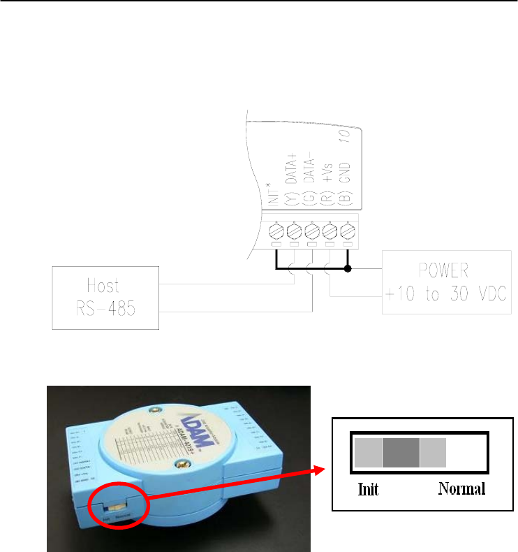
problem, most modules have an input terminal labeled INIT*. Booting
the module while connecting the INIT* terminal with the module’s
GND terminal forces the configuration into a known state called the
INIT* state. Besides, some newer modules have INIT switch which you
can set “Init” or “Normal” (See Figure 2.4). If you set the switch to
“Init”, then it becomes INIT* state.
INIT* state defaults:
Baud rate: 9600
Address: 00h
Checksum: disabled
Forcing the module in INIT* state does not change any parameters
in the module’s EEPROM. When the module is in the INIT* state with
its INIT* and GND terminals shorted, all configuration settings can be
changed, and the module will respond to all other commands normally.
Changing Baud rate and Checksum
Baud rate and checksum settings have several things in common:
• They should be the same for all modules and host computer.
• Their settings can only be changed by putting a module in the INIT*
state.
• Changed settings can only take effect after a module is rebooted
To alter baud rate or checksum settings, you must perform the
following steps:
Installation Guideline
2-
10
ADAM 4000 Series User’s Manual
• Power on all components except the ADAM Module.
• Power the ADAM module on while shorting the INIT* and GND
terminals (See Figure 2-3) or set the INIT switch to “Init” (See
Figure 2-4)
Figure 2-3 Grounding the INIT* Terminal
Figure 2-4 Set INIT switch to “Init”
• Configure the checksum status and/or the baud rate.
• Switch the power OFF to the ADAM Module.
• Remove the grounding of the INIT* terminal and turn on the
module, or set the INIT switch to “Normal”.
• Check the settings (If the baud rate has changed, the settings on the
host computer should be changed accordingly).
Chapter 2
Chapter 2 installation Guideline 2
-11
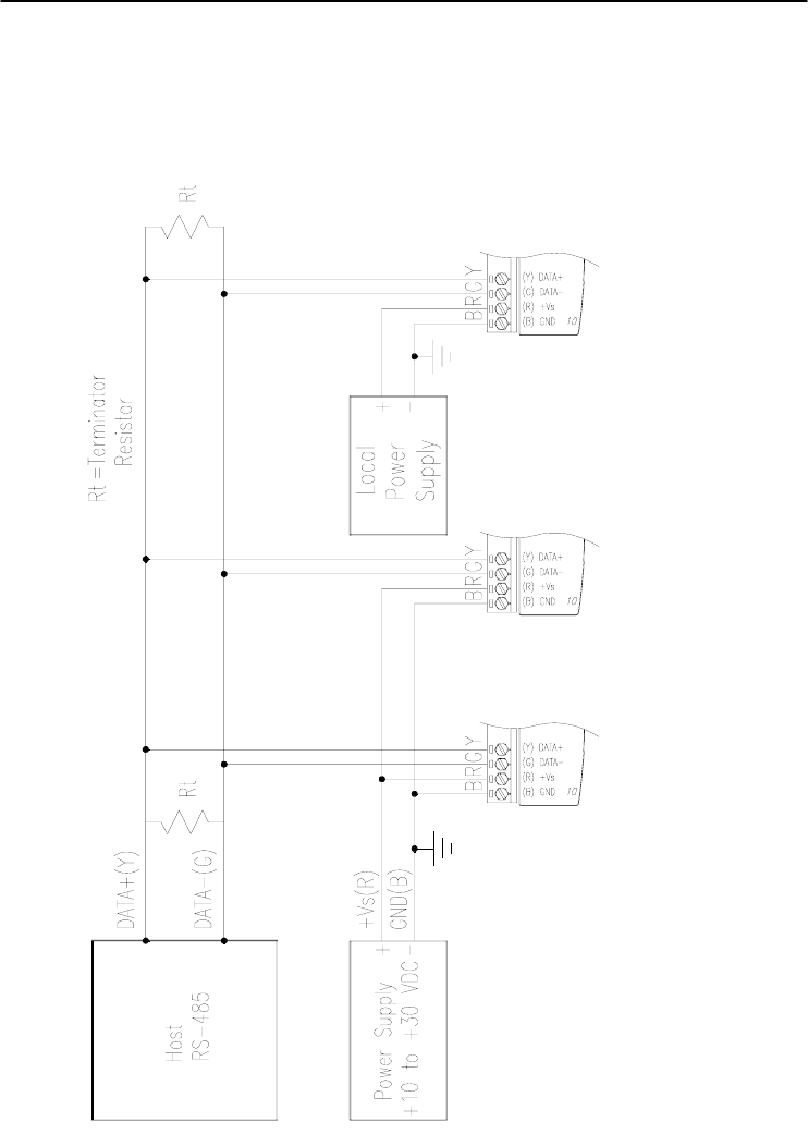
2.4 Multiple Module Hookup
The Figure below is an example of how ADAM modules are connected
in a multiple module network:
Figure 2-5 Multi-module Connection
Installation Guideline
2-
12
ADAM 4000 Series User’s Manual
2.5 Programming Example
The following example is a simple program written in Visual Basic 6.0
that demonstrates how to get temperature reading which is stored in the
address of 01H from ADAM-4011 module.
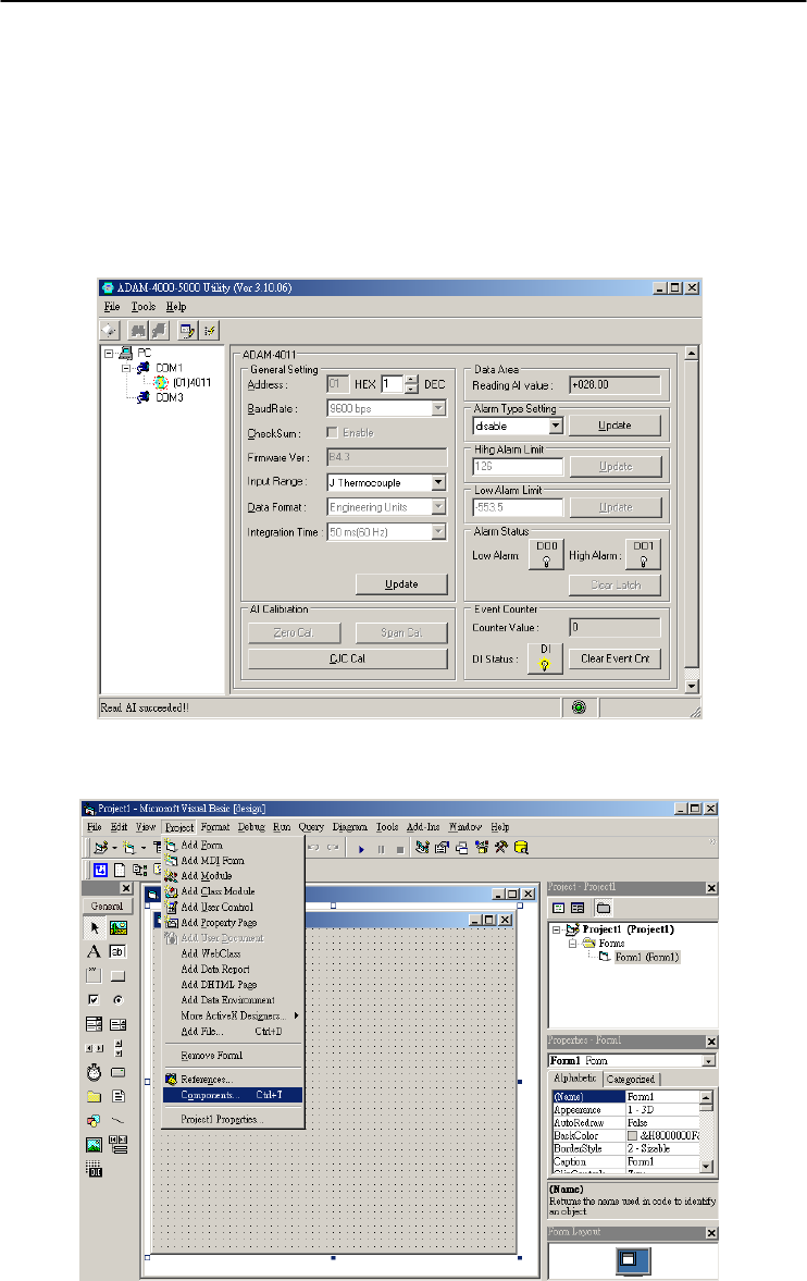
Step 1. Using ADAM Utility to check the settings as the following below:
“Address = 01H”, “Baud rate = 9600” and “Checksum = Disabled”.
Step 2. Run VB 6.0 and add a control via “Project\Component”.
Chapter 2
Chapter 2 installation Guideline 2
-13
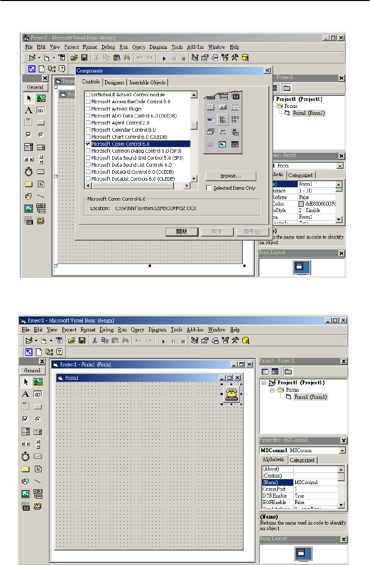
Step 3. Select “Microsoft Comm Control”
Step 4. Add the Comm Control on the form.
Installation Guideline
2-
14
ADAM 4000 Series User’s Manual
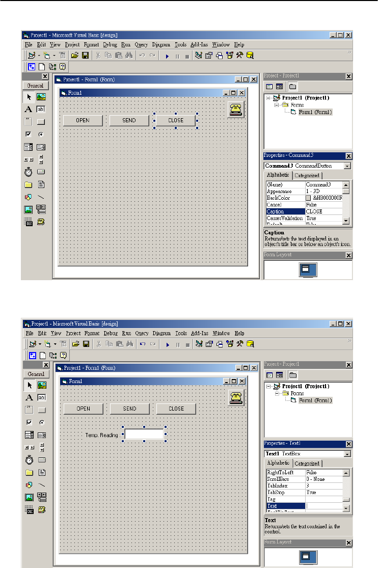
Step 5. Add three Command Buttons on the form as shown below
Step 6. Add one Label and one Text on the form as shown below.
Chapter 2
Chapter 2 installation Guideline 2
-15
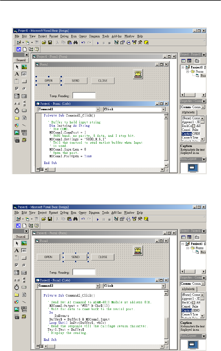
Step 7. Click OPEN Button and type in the following codes. The source
codes are listed at the end of this section.
Step 8. Click SEND Button and type in the following codes. The source
codes are listed at the end of this section.
Installation Guideline
2-
16
ADAM 4000 Series User’s Manual
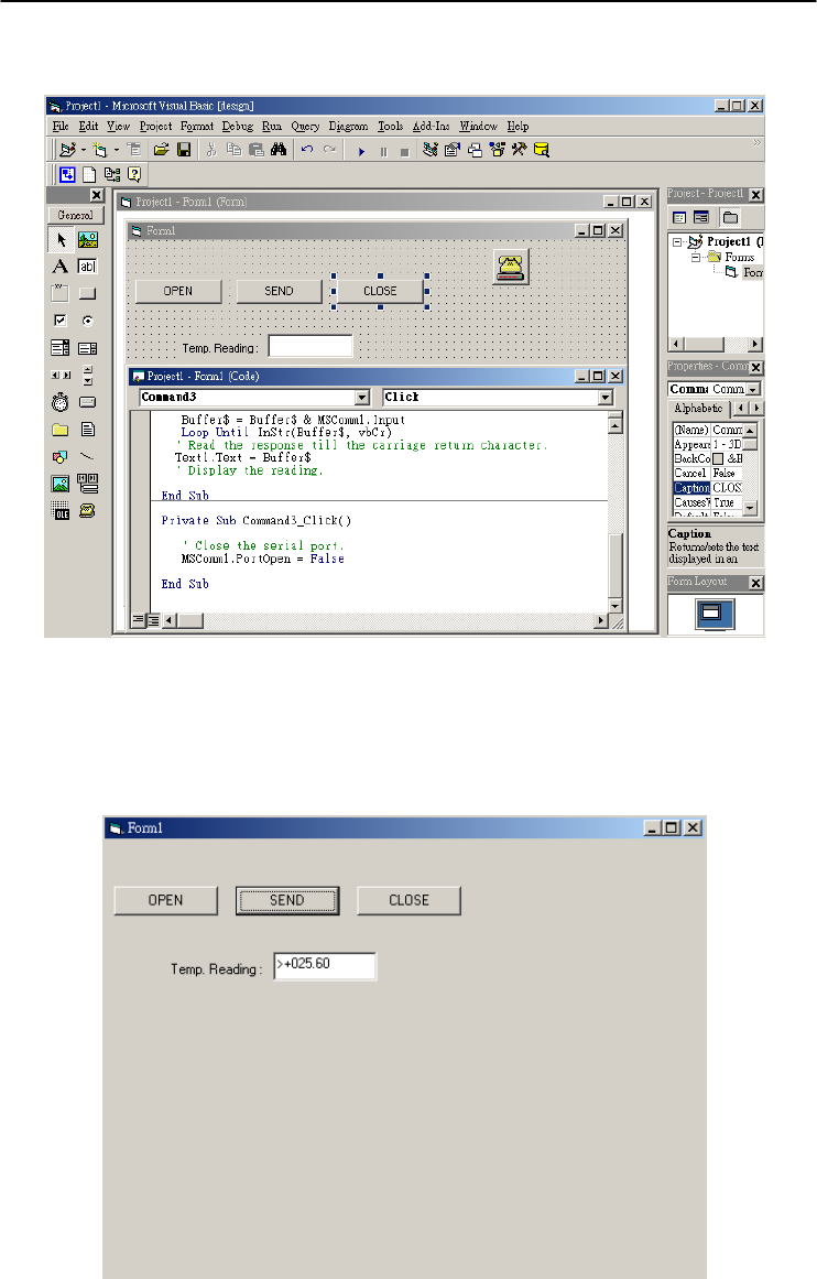
Step 9. Click CLOSE Button and type in the following codes. The source
codes are listed at the end of this section.
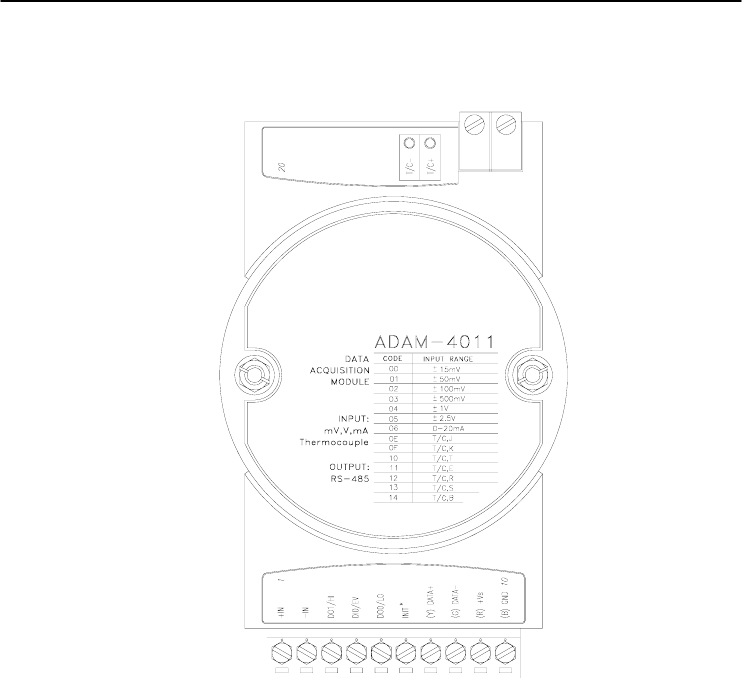
Step 10. Run the Project → Click OPEN to open COM1 → Click SEND to
send the Get Temperature Reading Command. Now, you will find the
reading the same as the displayed format shown below.

Chapter 2
Chapter 2 installation Guideline 2
-17
Program Source Codes:
OPEN Command Button:
Private Sub Command1_Click()
' Buffer to hold input string
Dim Instring As String
' Use COM1.
MSComm1.CommPort = 1
' 9600 baud, no parity, 8 data, and 1 stop bit.
MSComm1.Settings = "9600,N,8,1"
' Tell the control to read entire buffer when Input
' is used.
MSComm1.InputLen = 0
' Open the port.
MSComm1.PortOpen = True
End Sub
SEND Command Button:
Private Sub Command2_Click()
' Send Get AI command to ADAM-4011 Module at address 01H.
MSComm1.Output = "#01" & Chr$(13)
' Wait for data to come back to the serial port.
Do
DoEvents
Buffer$ = Buffer$ & MSComm1.Input
Loop Until InStr(Buffer$, vbCr)
' Read the response till the carriage return character.
Text1.Text = Buffer$
' Display the reading.
End Sub
CLOSE Command Button
Private Sub Command3_Click()
' Close the serial port.
MSComm1.PortOpen = False
End Sub
I/O Modules 3

I/O Modules
3-
2
ADAM 4000 Series User’s Manual
3.0 The common specification of ADAM-4000 I/O Series
Communication:
z RS-485 (2-wire) to host
z Speeds: 1200, 2400, 4800, 9600, 19200, 38400, 57600, 115200 bps
(ADAM-4080, ADAM-4080D only support up to 38400 bps)
z Max. communication distance: 4000 feet (1.2 km)
z Power and communication LED indicator
z ASCII command/response protocol
z Communication error checking with checksum
z Asynchronous data format: 1 start bit, 8 data bits, 1 stop bit, no parity
(N, 8, 1)
z Up to 256 multidrop modules per serial port
z Online module insertion and removal
z Transient suppression on RS-485 communication lines
Power Requirement:
z Unregulated +10 ~ +30 VDC
z Protected against power reversal
Mechanical:
z Case ABS+PC with captive mounting hardware
z Plug-in screw Accepts 0.5 mm2 to 2.5 mm2,
Terminal block #14 ~22 or #14~28 AWG
Environment
z EMI Meets FCC Class A or CE
z Operating Temperature -10 ~ 70° C (14 ~ 158° F)
z Storage Temperature -25 ~ 85° C (-13 ~ 185° F)
z Humidity 5 ~ 95%, non-condensing

Chapter 3
Chapter 3 I/O Modules
3-3
3.1 ADAM-4011/4011D Thermocouple Input Modules
The ADAM-4011/4011D Thermocouple Input Modules use a
microprocessor-controlled integrating A/D converter to convert sensor
voltage, current or thermocouple signal into digital data. The digital
data is then translated into either two’s complement hexadecimal
format or percentage of full-scale range (FSR) according to the
module’s configuration. When prompted by the host computer, the data
is sent through a standard RS-485 interface.
The ADAM-4011/4011D Thermocouple Input Modules offer signal
conditioning, A/D conversion, ranging, and RS-485 digital
communication functions. They protect your equipment from power
surges at the ground terminal by providing opto-isolation of the A/D
input and transformer based isolation up to 3000 VDC. (ADAM-4011
has transformer-based isolation up to 500 VDC)
Open Thermocouple Detection and Input Surge Protection
(ADAM-4011D only)
The ADAM-4011D provides an open thermocouple detection
function. Users can use a simple command to detect whether the
thermocouple is opened or closed. The module also provides surge
protection on its input channel. Internal high-speed transient suppressor
on its input channel protects the module from dangerous spikes and
voltages.
Front Panel LED Indicator (ADAM-4011D only)
The 4½ digits LED display on the back of the ADAM-4011D lets
you monitor the process readings right at their source. The module
displays readings in a wide variety of formats as well as high-low alarm
messages. The ADAM-4011D offers flexibility, easy installation, and
direct availability of process data. For critical process monitoring, this
module is the ideal choice.
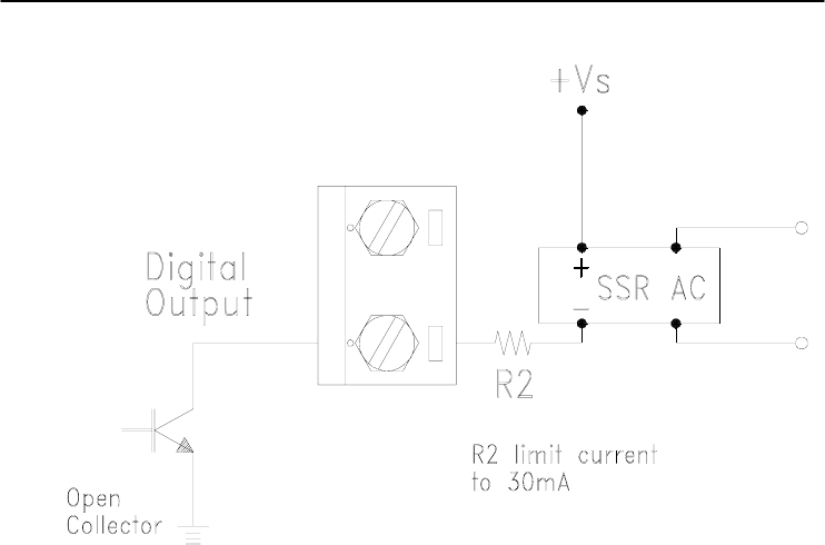
Digital Input/Output
The ADAM-4011/4011D Thermocouple Input Modules also contain
two digital outputs and one digital input. Outputs are open-collector
transistor switches that may be controlled by the host computer. They
can control solid-state relays, which may be used to control heaters,
pumps, and other electrical powered equipment. The digital inputs may
be read by the host computer and used to sense the state of a remote
digital signal.

I/O Modules
3-
4
ADAM 4000 Series User’s Manual
Event counting
The event counter is connected to the Digital Input channel and can
be used to keep track of the total amount of external low-speed pulses.
Its accumulated maximal count is 65535. The count will maintain at
65535 even if the actual number of events exceeds 65535. The counter
can be read or reset to zero by the host computer.
Since the Event counter’s data are not stored in EEPROM, the event
counter is cleared and set to zero after every reset or start up of the
analog input module.
Alarm signaling
Analog input modules include High and Low alarm functions. High
and Low alarm limits may be downloaded into the module’s EEPROM
by the host computer.
The alarm functions can be enabled or disabled remotely. When the
alarm function is enabled, both Digital Output channels are used to
indicate the High and Low alarm state. Digital Output channel 1 (DO1)
equals to High alarm state, and Digital Output channel 0 (DO0) equals
to Low alarm state. The High and Low alarm states can be read at any
time by the host computer.
Every A/D conversion will be followed by a comparison with the
High and Low limit. When the input value exceeds one of these limits,
the High or Low alarm state is set to ON.
There are two alarm mode options, Momentary and Latching. If the
alarm is in Latching mode, the alarm will stay on even if the input value
returns within the limits. An alarm in Latching mode can be turned OFF
by giving a Clear Alarm command from the host computer. A Latching
alarm is cleared by the module when the opposite alarm is set. When
the module receives a value that is lower than the Low alarm limit, it
will clear the High alarm and turn the Low alarm ON.
When the alarm is in Momentary mode, the alarm will be turned
OFF as soon as the input value returns within the limits.
The arrangement of coupling High and Low alarm states with
Digital Output lines may be utilized to build ON/OFF controllers that
can operate without the involvement of host computer.

Chapter 3
Chapter 3 I/O Modules
3-5
Function Description for the ADAM-4011 Thermocouple Input
Module
To provide a better understanding of the ADAM module functions,
the following is a description of the module ADAM-4011 with the most
extensive set of functions.
All analog input data first flow through the PGA (programmable
gain amplifier). The amplifier can vary its gain from 1 to 128. The PGA
then automatically adjusts the signal to a range from -2.5 V to +2.5 V.
This ensures an optimal input voltage and resolution for the A/D
converter.
The A/D conversion is supervised by the microprocessor that holds
the calibration software. Two kinds of calibrations, Auto Zero and Auto
Span calibrations, take place automatically in startup or reset. Normal
calibration is used to adjust the signal according to calibration
parameters defined by the user.
The digital 10 Hz filter provides a steady state output by using the
function.
Before the data enter the microprocessor, they pass through an
optical isolation device which prevents the chance of circuit damaging
caused by power surges from the ground terminal.
The microprocessor has six basic functions:
- Linearization of T/C (Thermocouple)
- Communication software and command set
- Calibration software
- Alarm monitoring
- Event counting
- Management of the EEPROM device that holds the system parameters
- Data transformation
After data have been transformed to the right data format, they are
being passed on to the RS-485 output port.
If an input value exceeds the High alarm setting or falls below the
Low alarm setting, a flag is set in one of the Digital Output channels.
Finally, the on-board switching regulator accepts voltage between +10
and +30 VDC, and it has an isolation value of 500 VDC to protect your
equipment from damages caused by power surges.
I/O Modules
3-
6
ADAM 4000 Series User’s Manual
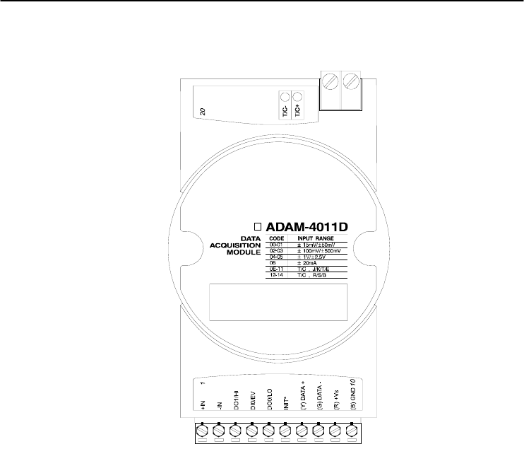
ADAM-4011 Thermocouple Input Module
Figure 3-1 ADAM-4011 Thermocouple Input Module
Accepts:
- J, K, T, E, R, S and B thermocouples
- Millivolt inputs: ±15 mV, ±50 mV, ±100 mV and ±500 mV
- Volt inputs: ±1 V and ±2.5 V
- Current input: ±20 mA (Requires a 125 resistor)
Two digital output channels and one digital input channel are provided.
Depending on the module’s configuration setting, it can forward the
data to the host computer in one of the following formats:
- Engineering units (o C, mV, V or mA)
- Percent of full-scale range (FSR)
- Two’s complement hexadecimal
Chapter 3
Chapter 3 I/O Modules
3-7
ADAM-4011D Thermocouple Input Module
Figure 3-2 ADAM-4011D Thermocouple Input Module with LED Display
Accepts:
- J, K, T, E, R, S and B thermocouples
- Millivolt inputs: ±15 mV, ±50 mV, ±100 mV and ±500 mV
- Volt inputs: ±1 V and ±2.5 V
- Current input: ±20 mA (Requires a 125 resistor)
Two digital output channels and one digital input channel are provided.
Depending on the module’s configuration setting, it can forward the
data to the host computer in one of the following formats:
- Engineering units (oC, mV, V, or mA)
- Percent of full-scale range (FSR)
- Two’s complement hexadecimal
I/O Modules
3-
8
ADAM 4000 Series User’s Manual
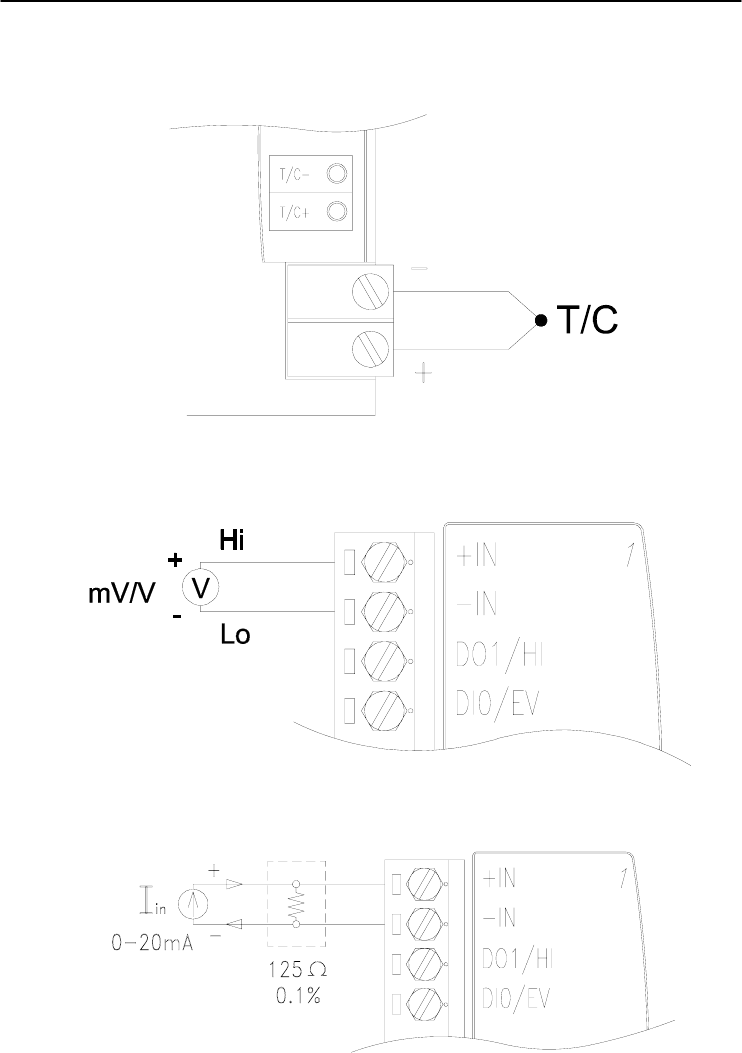
Application Wiring
Figure 3-3 ADAM-4011/4011D Thermocouple Input Wiring Diagram
Figure 3-4 ADAM-4011/4011D Millivolt and Volt Input Wiring Diagram
Figure 3-5 ADAM-4011/4011D Process Current Input Wiring Diagram
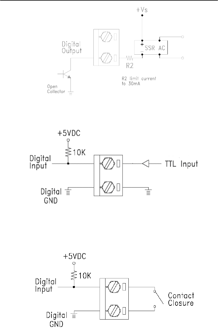
Chapter 3
Chapter 3 I/O Modules
3-9
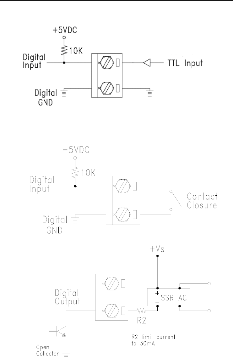
Figure 3-6 ADAM-4011/4011D Digital Output Wiring Diagram
Used with SSR (HI-LO alarm)
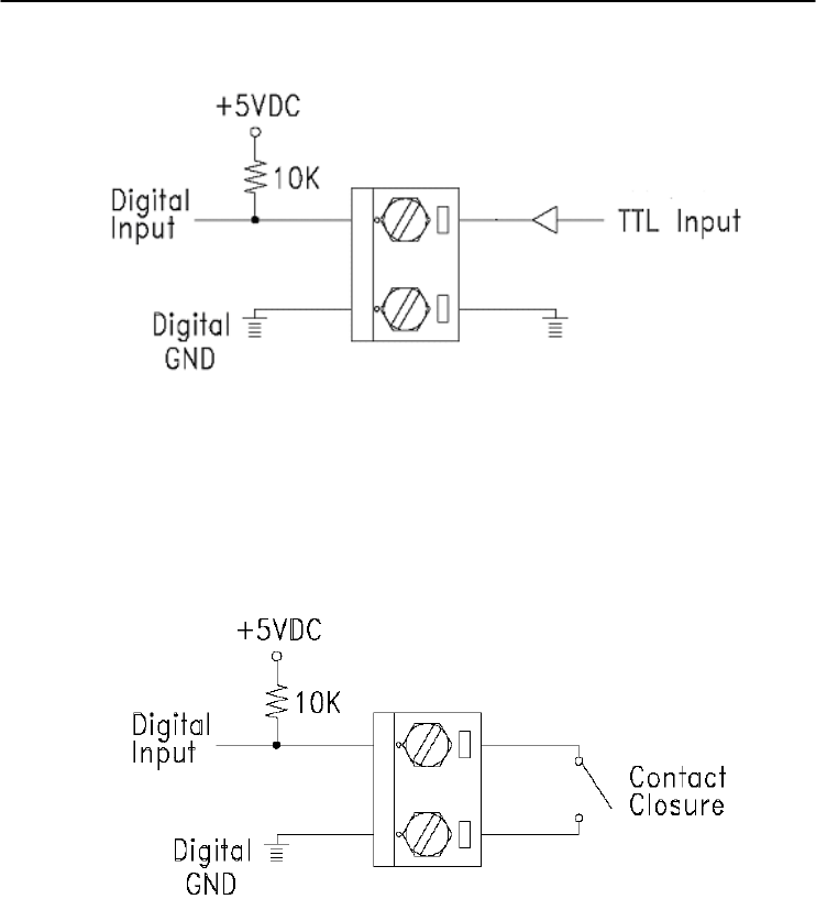
Figure 3-7 ADAM-4011/4011D Digital Input Wiring Diagram
Used with TTL
Figure 3-8 ADAM-4011/4011D Digital Input Wiring Diagram
Used with Dry contact

I/O Modules
3-
10
ADAM 4000 Series User’s Manual
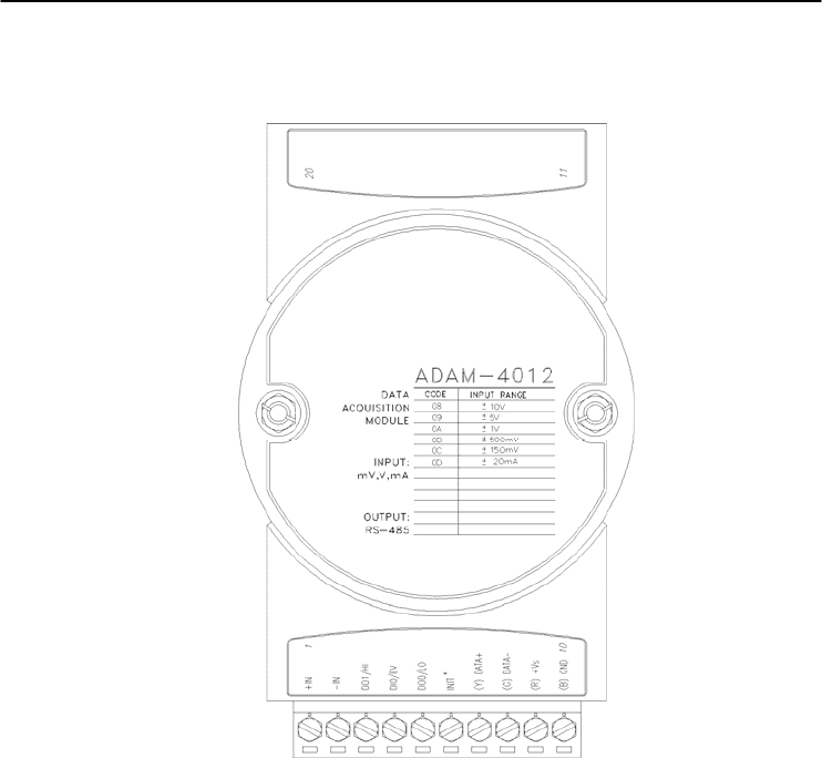
3.2 ADAM-4012 Analog Input Module
The ADAM-4012 Analog Input Modules use a microprocessor-
controlled integrating A/D converter to convert sensor voltage or
current signals into digital data. The digital data are then translated into
either two’s complement hexadecimal format or percentage of full-scale
range (FSR) according to the module’s configuration. When prompted
by the host computer, the data are sent through a standard RS-485
interface.
The ADAM-4012 Analog Input Modules offer signal conditioning,
A/D conversion, ranging, and RS-485 digital communication functions.
They protect your equipment from power surges at the ground terminal
by providing opto-isolation of the A/D input and up to 3000 VDC
transformer based isolation.
Digital Inputs/Outputs
The ADAM-4012 also contains two digital outputs and one digital
input. Outputs are open-collector transistor switches that may be
controlled by the host computer. They can control solid-state relays,
which can be applied to heaters, pumps, and other electrical powered
equipment. The digital inputs may be read by the host computer and
used to sense the state of a remote digital signal.
Event counting
The event counter is connected to the Digital Input channel and can
be used to keep track of the total amount of external low-speed pulses.
Its accumulated maximal count is 65535. The number 65535 is held
even if the actual number of events exceeds 65535. The counter can be
read or reset to zero by the host computer.
Since the Event counter’s data are not stored in EEPROM, the event
counter is cleared and set to zero after every reset or start up of the
analog input module.

Chapter 3
Chapter 3 I/O Modules
3-11
Alarm signaling
Analog input modules include High and Low alarm functions. High
and Low alarm limits may be downloaded into the module’s EEPROM
by the host computer.
The alarm functions can be enabled or disabled remotely. When the
alarm function is enabled, both Digital Output channels are used to
indicate the High and Low alarm states. Digital Output channel 1 (DO1)
equals to High alarm state, and Digital Output channel 0 (DO0) equals
to Low alarm state. The High and Low alarm states can be read at any
time by the host computer.
Every A/D conversion will be followed by a comparison with the
High and Low limit. When the input value exceeds one of these limits,
the High or Low alarm state is set to ON.
There are two alarm mode options, Momentary and Latching.
If the alarm is in Latching mode, the alarm will stay on even when
the input value returns within the limits. It can also be turned OFF by
issuing a Clear Alarm command from the host computer. A Latching
alarm is cleared by the module when the opposite alarm is set.
When the module receives a value that is lower than the Low alarm
limit, it will clear the High alarm and turn the Low alarm ON.
When the alarm is in Momentary mode, the alarm will be turned OFF
as soon as the input value returns within the limits.
The arrangement of coupling High and Low alarm states with
Digital Output lines may be utilized to build ON/OFF controllers that
can operate without involving the host computer.
I/O Modules
3-
12
ADAM 4000 Series User’s Manual
ADAM-4012 Analog Input Module
Figure 3-9 ADAM-4012 Analog Input Module
Accepts:
- Millivolt inputs ± 150 mV and ±500 mV
- Volt inputs: ±1 V, ±5 V and ±10 V
- Current input: ±20 mA (requires a 125 resistor)
Two digital output channels and one digital input channel are provided.
Depending on the module's configuration setting, it can forward the
data to the host computer in one of the following formats:
- Engineering units (mV, V, or mA)
- Percent of full-scale range (FSR)
- Two’s complement hexadecimal
Chapter 3
Chapter 3 I/O Modules
3-13
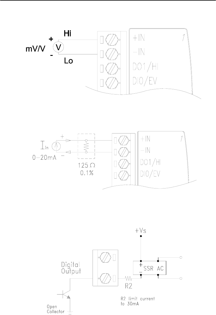
Application Wiring
Figure 3-10 ADAM-4012 Millivolt and Volt Input Wiring Diagram
Figure 3-11 ADAM-4012 Process Current Input Wiring Diagram
Figure 3-12 ADAM-4012 Digital Output Wiring Diagram
Used with SSR (HI-LO alarm)
I/O Modules
3-
14
ADAM 4000 Series User’s Manual
Figure 3-13 ADAM-4012 Digital Input Wiring Diagram Used with TTL
Figure 3-14 ADAM-4012 Digital Input Wiring Diagram
Used with Dry contact
Chapter 3
Chapter 3 I/O Modules
3-15
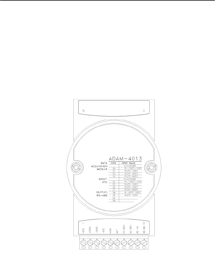
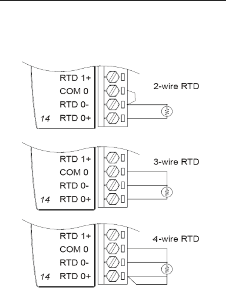
3.3 ADAM-4013 RTD Module
The ADAM-4013 RTD Input Module supports one Pt or Ni RTD
input channel for temperature measurement. This module can accept
RTD sensors with two, three, or four wires. The module offers signal
conditioning, A/D conversion, ranging, and RS-485 digital
communication functions. It protects your equipment from power
surges at the ground terminal by providing opto-isolation of the A/D
input and up to 3000 VDC transformer based isolation.
Figure 3-15 ADAM-4013 RTD Input Module
Accepts:
- Input from platinum and nickel RTDs
Depending on the module’s configuration setting, it can forward the
data to the host computer in one of the following formats:
- Engineering units (°C)
- Percent of full-scale range (FSR)
- Two’s complement hexadecimal
I/O Modules
3-
16
ADAM 4000 Series User’s Manual
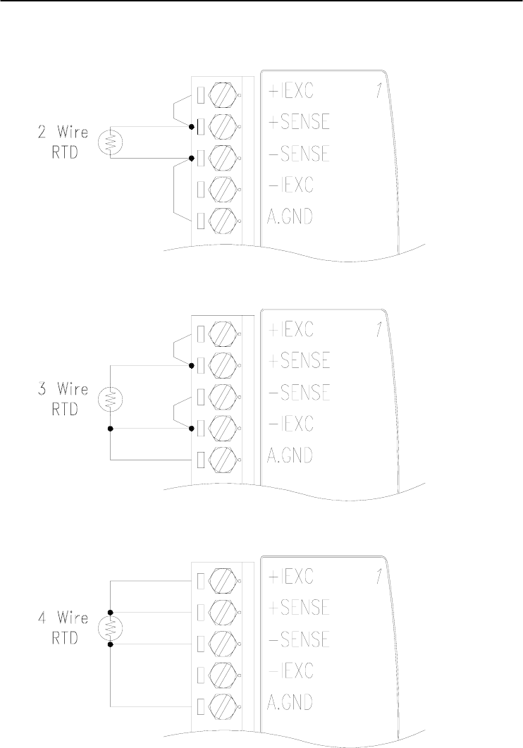
Application Wiring
Figure 3-16 ADAM-4013 RTD Inputs Wiring Diagram
Chapter 3
Chapter 3 I/O Modules
3-17
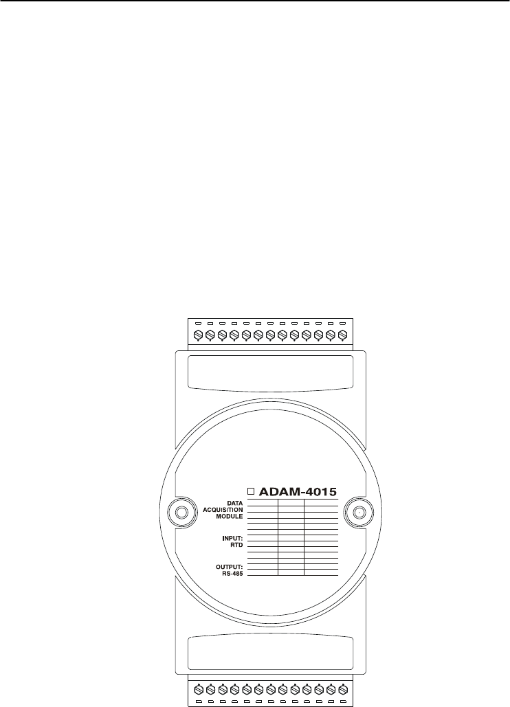
3.4 ADAM-4015 6-channel RTD Input Module
A RTD module is popularly used for temperature measurement.
Unlike the traditional design, the ADAM-4015 RTD Input Module
provides six RTD input channels for different types of RTD signal like
as Pt, Ni, Balco. It is an effective solution in industrial & building
automation. Normally, broken external wire will lead to an inaccurate
current value; however, the ADAM-4015 provides a broken wire
detecting function. Therefore, users can easily fix the broken wire
problems. This module can accept RTD sensors that have two or three
wires. After the V2.04 of ADAM-4015, ADAM-4015 can support the
“BA1 -200~600℃”
26
COM 4
RTD4-
RTD4+
COM 5
RTD5-
RTD5+
N/A
INIT*
(Y) D
A
T
A+
(G)D
A
T
A-
(R) +Vs
(B) GND
N/A
1
1314
CODE TYPE
(IEC/JIS) 30/35
(IEC/JIS) 30/35
(IEC/JIS) 30/35
(IEC/JIS) 30/35
(IEC/JIS) 30/35
40
41
42
43
RANGE
Pt 100
-
-
-
-
Pt 1000
BALCO 500
Ni
Ni
-50
蚓
- 150
蚓
0
蚓
- 100
蚓
0
蚓
- 200
蚓
0
蚓
- 400
蚓
-200
蚓
- 200
蚓
-40
蚓
- 160
蚓
-30
蚓
- 120
蚓
-80
蚓
- 100
蚓
0
蚓
- 100
蚓
GND
COM 3
RTD3-
RTD3+
COM 2
RTD2-
RTD2+
COM 1
RTD1-
RTD1+
COM 0
RTD0-
RTD0+
Figure 3-17 ADAM-4015 6-channel RTD Input Module
I/O Modules
3-
18
ADAM 4000 Series User’s Manual
Application Wiring
Figure 3-18 ADAM-4015 RTD Input Module Wiring Diagram

Chapter 3
Chapter 3 I/O Modules
3-19
Technical specification of ADAM-4015
Channel Number 6 differential
Support Protocol ADAM ASCII and MODBUS/RTU
Input Type Pt100, Pt1000, BALCO500, Ni
Input Connections 2 or 3 wires
Wire Burnout Detection Yes
Input Type and
Temperature Range
Pt100: -50 to 150° C
0 to 100° C
0 to 200° C
0 to 400° C
-200 to 200° C
Pt1000: -40 to 160° C
Balco500: -30 to 120° C
Ni 50 RTD: -80 to 100° C
Ni 508 RTD: 0 to 100° C
Isolation Voltage 3000 VDC
Sampling Rate 10 sample/second (total)
Input Impedance 10 M
Resolution 16-bit
Accuracy ±0.1% or better
CMR@50/60Hz 120 dB
NMR@50/60Hz 100 dB
Span Drift ± 25 ppm/℃
Zero Drift ± 3 V/℃
Watchdog Timer System (1.6 second) and Communication
Power Input +10~+30 VDC (non-regulated)
Power Consumption 1.2 W @ 24VDC
Table 3-1 Technical specification of ADAM-4015
I/O Modules
3-
20
ADAM 4000 Series User’s Manual
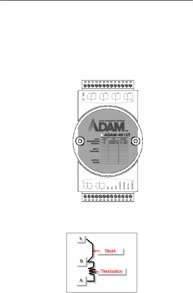
3.5 ADAM-4015T 6-channel Thermistor Input Module
A Thermistor Module is popularly used for temperature
measurement. Unlike the traditional design, the ADAM-4015T
provides six thermistor input channels for thermistor signal. It is an
effective solution in industrial & building automation. Normally,
broken external wires will lead to an inaccurate current value. The
ADAM-4015T provides a broken wire detecting function, so users
can easily fix the problems.
Figure 3-19 ADAM-4015T 6-channel Thermistor Input Module
Application Wiring
Figure 3-20 ADAM-4015T Thermistor Input Module Wiring Diagram

Chapter 3
Chapter 3 I/O Modules
3-21
Technical specification of ADAM-4015T
Channel Number 6 differential
Support Protocol ADAM ASCII and MODBUS/RTU
Input Type Thermistor
Input Connections 2 or 3 wires
Wire Burnout Detection Yes
Input Type and
Temperature Range
Thermistor 3k 0~100℃
Thermistor 10k 0~100℃
Isolation Voltage 3000 VDC
Sampling Rate 10 sample/second (total)
Input Impedance 10 M
Resolution 16-bit
Accuracy ±0.1% or better
CMR@50/60Hz 120 dB
NMR@50/60Hz 100 dB
Span Drift ± 25 ppm/℃
Zero Drift ± 3 V/℃
Watchdog Timer System (1.6 second) and Communication
Power Input +10~+30 VDC (non-regulated)
Power Consumption 1.2 W @ 24VDC
Table 3-2 Technical specification of ADAM-4015T

I/O Modules
3-
22
ADAM 4000 Series User’s Manual
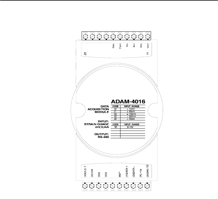
3.6 ADAM-4016 Analog Input/Output Module
A strain gauge input module uses a microprocessor-controlled
integrating A/D converter to convert sensor voltage or current signals
into digital data for load cell and stress measurement. The digital data
are then translated into either, two’s complement hexadecimal format or
percentage of full-scale range (FSR) according to the module’s
configuration. When prompted by the host computer, the data are sent
through a standard RS-485 interface.
The strain gauge input module offers signal conditioning, A/D
conversion, ranging, and RS-485 digital communication functions.
They protect your equipment from power surges at the ground terminal
by providing opto-isolation of the A/D input and up to 3000 VDC
transformer based isolation.
Excitation Voltage Output
A strain gauge input module can supply single channel voltage
output for excitation. The module receives digital input from the host
computer, and the format of the data is engineering units. It then uses
its microprocessor-controlled D/A converter to convert the digital data
into output signals.
Strain gauge input modules protect your equipment from power
surges at the ground terminal by providing opto-isolation of the D/A
output and up to 3000 VDC transformer-based isolation.
Digital Outputs
A strain gauge input module also contains four digital outputs.
Outputs are open-collector transistor switches that may be controlled by
the host computer. They can control solid-state relays which can be
applied to heaters, pumps, and other electrical controlled equipments.
Alarm signaling
Strain Gauge input modules include High and Low alarm functions.
High and Low alarm limits may be downloaded into the module’s
EEPROM by the host computer.
The alarm functions can be enabled or disabled remotely. When the
alarm function is enabled, both Digital Output channels are used to
indicate the High and Low alarm states. Digital Output channel 1 (DO1)
equals to High alarm state and Digital Output channel 0 (DO0) equals
to Low alarm state. The High and Low alarm state can be read at any
time by the host computer.

Chapter 3
Chapter 3 I/O Modules
3-23
Every A/D conversion will be followed by a comparison with the
High and Low limits. When the input value exceeds one of these limits,
the High or Low alarm state is set to ON.
There are two alarm mode options, Momentary and Latching. If the
alarm is in Latching mode, the alarm will stay on even when the input
value returns within limits. An alarm in Latching mode can be turned
OFF by issuing a Clear Alarm command from the host computer. A
Latching alarm is cleared by the module when the opposite alarm is set.
When the module receives a value that is lower than the Low alarm
limit, it will clear the High alarm and turn the Low alarm ON.
When the alarm is in Momentary mode, the alarm will be turned
OFF as soon as the input value returns to within limits.
The arrangement of coupling High and Low alarm states with
Digital Output lines may be utilized to build ON/OFF controllers that
can operate without the host computer involvement.
I/O Modules
3-
24
ADAM 4000 Series User’s Manual
ADAM-4016 Analog Input/Output Module
Figure 3-21 ADAM-4016 Analog Input/Output Module
Accepts:
- Millivolt inputs: ±15 mV, ±50 mV, ±100 mV, ±500 mV
- Current input: ±20 mA
Excitation voltage output: 0 ~ 10 V
Four digital output channels are provided.
Depending on the module’s configuration setting, it can forward the
data to the host computer in one of the following formats:
- Engineering units (mV or mA)
- Percent of full-scale range (FSR)
- Two’s complement hexadecimal
Chapter 3
Chapter 3 I/O Modules
3-25
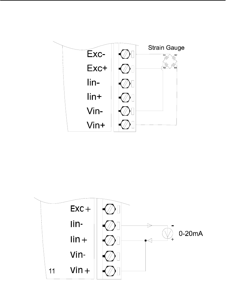
Application Wiring
Figure 3-22 ADAM-4016 Strain Gauge Voltage Input Wiring Diagram
Figure 3-23 ADAM-4016 Strain Gauge Current Input Wiring Diagram
I/O Modules
3-
26
ADAM 4000 Series User’s Manual
Figure 3-24 ADAM-4016 Digital Output Wiring Diagram Used with SSR

Chapter 3
Chapter 3 I/O Modules
3-27
3.7 ADAM-4017/4017+/4018/4018M/4018+ 8-channel Analog Input Modules
ADAM-4017/4018 8-channel Analog Input Module
The ADAM-4017/4018 is a 16-bit, 8-channel analog input module
that provides programmable input ranges on all channels. This module
is an extremely cost-effective solution for industrial measurement and
monitoring applications. Its opto-isolated inputs provide 3000 VDC of
isolation between the analog input and the module, and protect the
module and peripherals from damaging due to high input-line voltages.
The ADAM-4017/4018 offers signal conditioning, A/D conversion,
ranging and RS-485 digital communication functions. The module
protects your equipment from power surges at the ground terminal by
providing opto-isolation of A/D input and up to 3000 VDC transformer
based isolation.
The ADAM-4017/4018 uses a 16-bit microprocessor-controlled
sigma-delta A/D converter to convert sensor voltage or current into
digital data. The digital data are then translated into engineering units.
When prompted by the host computer, the module sends the data to the
host through a standard RS-485 interface.
ADAM-4018M 8-channel Analog Input Data logger
The ADAM-4018M is a 16-bit, 8-channel analog input data logger
featuring programmable input ranges on all channels. This reliable and
easy to use analog input logger can store up to 38,000 measurements
for a maximum duration of 20 years.
The ADAM-4018M can accept various analog inputs such as
thermocouple, mV, V and mA. It also offers three configurable logging
modes, standard log, event log, and mixed log. Optically isolated inputs
provide 3000 VDC of isolation between the module and the analog input,
and protect the module and peripherals from damaging due to high
voltages on the input lines.
The ADAM-4018M is an extremely cost-effective solution for
industrial measurement and monitoring applications.

I/O Modules
3-
28
ADAM 4000 Series User’s Manual
ADAM-4017+ 8-channel Differential Analog Input Module
Here comes a solution to the demand for more analog input channels.
Similar to its counterpart, the ADAM-4017+ enables eight differential
channels with multiple input ranges. This multi-channel/multi-range
structure allows channels with different input ranges at the same time.
For example, channel 1 can have the range ± 5V meanwhile the others
are ± 10V and ± 20 mA.
Instead of leaving two single-ended channels in ADAM-4017
module due to the limit number of pins, ADAM-4017+ uses a switch
to switch AGND and INIT* to Vin6- and Vin7- respectively to allow 8-
channel input. Moreover, the ADAM-4017+ has been expanded to
accept 4 ~ 20 mA, so the user can employ it in various applications
ADAM-4018+ 8-channel Thermocouple Input Module
Here comes a solution to the demand for more thermocouple input
channels. Similar to its counterpart, the ADAM-4018+ enables eight
differential channels with multiple input types. This multi-
channel/multi-type structure allows synchronizing channels with
different types of input. For example, channel 1 has K type of input
meanwhile the others have R and S types.
ADAM-4018+ is an 8-channel T/C input module. Comparing with
the universal analog input module ADAM-4019, it is more dedicated to
T/C and 4 ~ 20 mA inputs for those with special request. It improves
ADAM-4018 with the traditional design of six differential and two
single-ended channels. It also enhances the steadiness and reliability of
the wiring. Normally, broken external wires will lead to an inaccurate
current value. ADAM-4018+, however, provides burned-out detection
that allows users to fix the problems easily. ADAM 4018+ has build in
Shunt.
Chapter 3
Chapter 3 I/O Modules
3-29
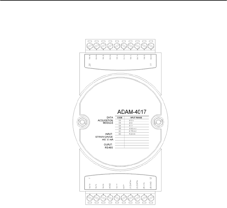
ADAM-4017 8-channel Analog Input Module
Figure 3-25 ADAM-4017 8-channel Analog Input Module
Channels:
- Six differential, two single-ended
Accepts:
- Millivolt inputs: ±150 mV and ±500 mV
- Volt inputs: ±1 V, ±5 V, and ±10 V
- Current input: ±20 mA (requires a 120 resistor)
The module forwards the data to the host computer in engineering units
(mV, V or mA)
I/O Modules
3-
30
ADAM 4000 Series User’s Manual
ADAM-4017+ 8-channel Differential Analog Input Module
Figure 3-26 ADAM-4017+ 8-ch. differential analog input module
Jumper setting (ADAM-4017+)
1. JP0~JP7
JP0~
JP7 20 mA Input Range
Voltage Input range
Mapping to
Channel
Ch.
1
Ch.
2
Ch.
3
Ch.
4 Ch.5 Ch.6 Ch.7 Ch.8
JP 0 JP 2 JP 4 JP 6 JP 1 JP 3 JP 5 JP 7
2. JP12 can Enable/Disable Watchdog Timer Function. The default
setting is closed, i.e., Watchdog Timer Function Enabled. Please
always keep JP12 closed and enable/disable the watchdog timer
function in ADAM-utility.
A
DAM-4017+
CODE INPUT RANGE
08
09
0A
0B
0C
DATA
ACQUISITION
MODULE
INPUT:
STRAIN GAUGE
mV, V, m
A
OUPUT:
RS-485
0D
±10 V
±5 V
±1 V
±500 m
V
±100 m
V
±20 m
A
07 4 ~20 m
A
Vin5+
Vin5-
Vin6+
Vin6-
Vin7+
Vin7-
(Y)Data+
(G)Data-
(R)Vs+
(B)GND
Vin4+
Vin4-
Vin3+
Vin3-
Vin2+
Vin2-
Vin1+
Vin1-
Vin0+
Vin0-
Chapter 3
Chapter 3 I/O Modules
3-31
Technical specification of ADAM-4017+
Channel 8
Input Type mV, V, mA
Input Range ±150 mV, ±500 mV, ±1 V, ±5 V, ±10 V,
±20 mA, 4 ~ 20 mA
Isolation Voltage 3000 VDC
Fault and Over-voltage
protection With stands over-voltage up to ±35 V
Sampling Rate 10 sample/sec (total)
Input Impedance Volta
g
e: 20 M, Current: 120
Accuracy ±0.1% or better
Power Consumption 1.2 W
@
24VDC
I/O Connector Type 10 pin plug-in terminal
Table 3-3 Technical specification of ADAM-4017+
I/O Modules
3-
32
ADAM 4000 Series User’s Manual
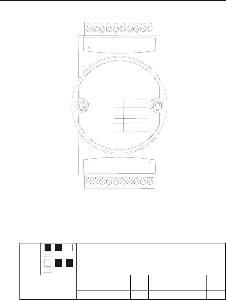
ADAM-4018 8-channel Analog Input Module
ADAM-4018
CODE INPUT RANGE
00
01
02
03
04
DATA
ACQUISITION
MODULE
Vin 0+
Vin 0-
Vin 1+
Vin 5+
Vin 5-
Vin 6+
INIT*
(Y) DATA+
(G) DATA-
(R) +Vs
(B) GND
Vin 1-
Vin 4+
Vin 4-
AGND
INPUT:
Thermocouple
mV, V, mA
OUPUT:
RS-485
05
?5 mV
?0 mV
?00 mV
?00 mV
? V
?.5 V
Vin 7+
Vin 3-
Vin 3+
Vin 2-
Vin 2+
?0 mA
T/C J
T/C K
T/C T
T/C E
T/C R
T/C S
T/C B
06
DE
DF
10
11
12
13
14
Figure 3-27 ADAM-4018 8-channel Thermocouple Input Module
Channels:
- Six differential, two single-ended
Accepts:
- J, K, T, E, R, S and B thermocouples
- Millivolt inputs: ±15 mV, ±50 mV, ±100 mV and ±500 mV
- Volt inputs: ±1 V and ±2.5 V
- Current input: ±20 mA (requires a 125 resistor)
The module forwards the data to the host computer in engineering units
(oC, mV, V or mA)

Chapter 3
Chapter 3 I/O Modules
3-33
ADAM-4018M 8-channel Analog Input Data logger
ADAM-4018M
CODE INPUT RANGE
00
01
02
03
04
DATA
ACQUISITION
MODULE
Vin 0+
Vin 0-
Vin 1+
Vin 5+
Vin 5-
Vin 6+
INIT*
(Y) DATA+
(G) DATA-
(R) +Vs
(B) GND
Vin 1-
Vin 4+
Vin 4-
AGND
INPUT:
Thermocouple
mV, V, mA
OUPUT:
RS-485
05
?5 mV
?0 mV
?00 mV
?00 mV
? V
?.5 V
Vin 7+
Vin 3-
Vin 3+
Vin 2-
Vin 2+
?0 mA
T/C J
T/C K
T/C T
T/C E
T/C R
T/C S
T/C B
06
DE
DF
10
11
12
13
14
Figure 3-28 ADAM-4018M 8-channel Analog Input Data Logger
Channels:
- Six differential, two single-ended
Accepts:
- J, K, T, E, R, S and B thermocouples
- Millivolt inputs: ±15 mV, ±50 mV, ±100 mV, ±500 mV
- Volt inputs: ±1 V and ±2.5 V
- Current input: ±20 mA (requires a 125 resistor)
The module forwards the data to the host computer in engineering units
(oC, mV, V, or mA)
Storage Capacity:
- 128 KB flash memory
I/O Modules
3-
34
ADAM 4000 Series User’s Manual
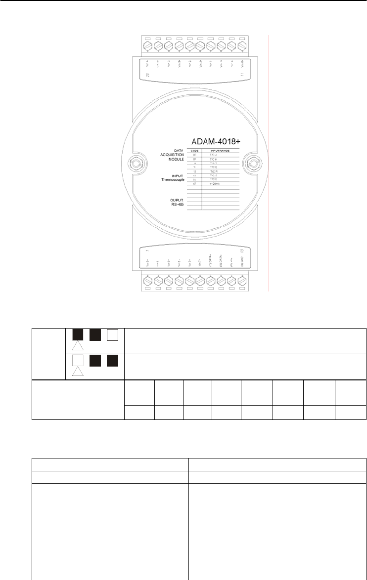
ADAM-4018+ 8-channel Thermocouple Input Module
Figure 3-29 ADAM-4018+ 8-ch. thermocouple input module
JP0~
JP7 4~20 mA Input Range
Voltage Input range
Mapping to
Channel
Ch.
1
Ch.
2
Ch.
3
Ch.
4 Ch.5 Ch.6 Ch.7 Ch.8
JP 0 JP 2 JP 4 JP 6 JP 1 JP 3 JP 5 JP 7
Technical specification of ADAM-4018+
Channel 8
Input Type Thermocouple
Input range and T/C type ±20 mA, 4~20 mA
J 0 ~ 760° C
K 0 ~ 1370° C
T -100 ~ 400° C
E 0 ~ 1000° C
R 500 ~ 1750° C
S 500 ~ 1750° C
B 500 ~ 1800° C
Chapter 3
Chapter 3 I/O Modules
3-35
Isolation Voltage 3000 VDC
Fault and over-voltage protection Withstands over voltage up to ±35 V
Sampling Rate 10 sample/sec (total)
Input Impedance Voltage: 20 M, Current: 120
Accuracy ±0.1% or better
Power Consumption 0.8 W @ 24VDC
I/O Connector Type 10 pin plug-in terminal
Table 3-4 Technical specification of ADAM-4018+
Application Wiring
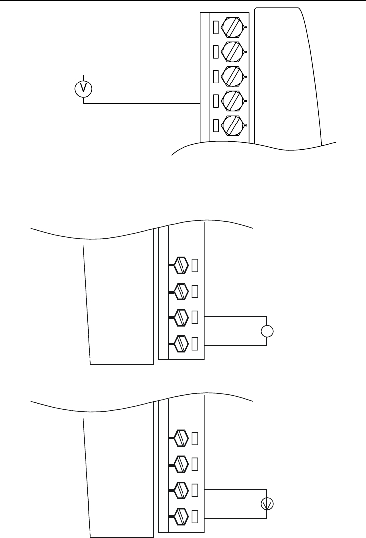
Figure 3-30 Current Input Wiring Diagram of ADAM-4017
Vin0-
Vin0+
11
V
-
+
mV/V
Figure 3-31(a) ADAM-4017 Differential Input Wiring Diagram (Ch0 ~ Ch5)
I/O Modules
3-
36
ADAM 4000 Series User’s Manual
Vin5-
Vin5+
1
Vin6+
mV/V
-
+
AGND
Vin7+
Figure 3-31(b) ADAM-4017 Single-ended Input Wiring Diagram (Ch6 and Ch7)
11 Vin 0+
Vin 0-
Vin 1+
Vin 1-
mV/V
V
+
-
11 Vin 0+
Vin 0-
Vin 1+
Vin 1-
±
4~20 mA
+
-
Built-in 125 Ohm Resister
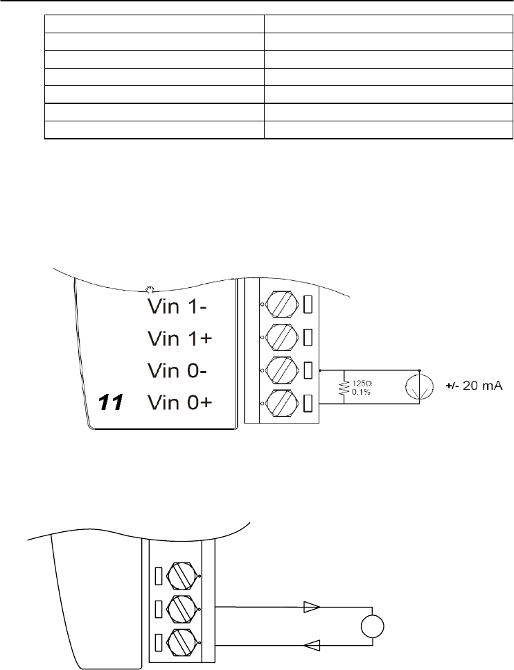
Figure 3-32 ADAM-4017+ Voltage and Current Input Wiring Diagram
Chapter 3
Chapter 3 I/O Modules
3-37
11 Vin 0+
Vin 0-
Vin 1+
Vin 1-
T/C or 4~20m
A
+
-
Figure 3-33 ADAM-4018+ Thermocouple Input Wiring Diagram
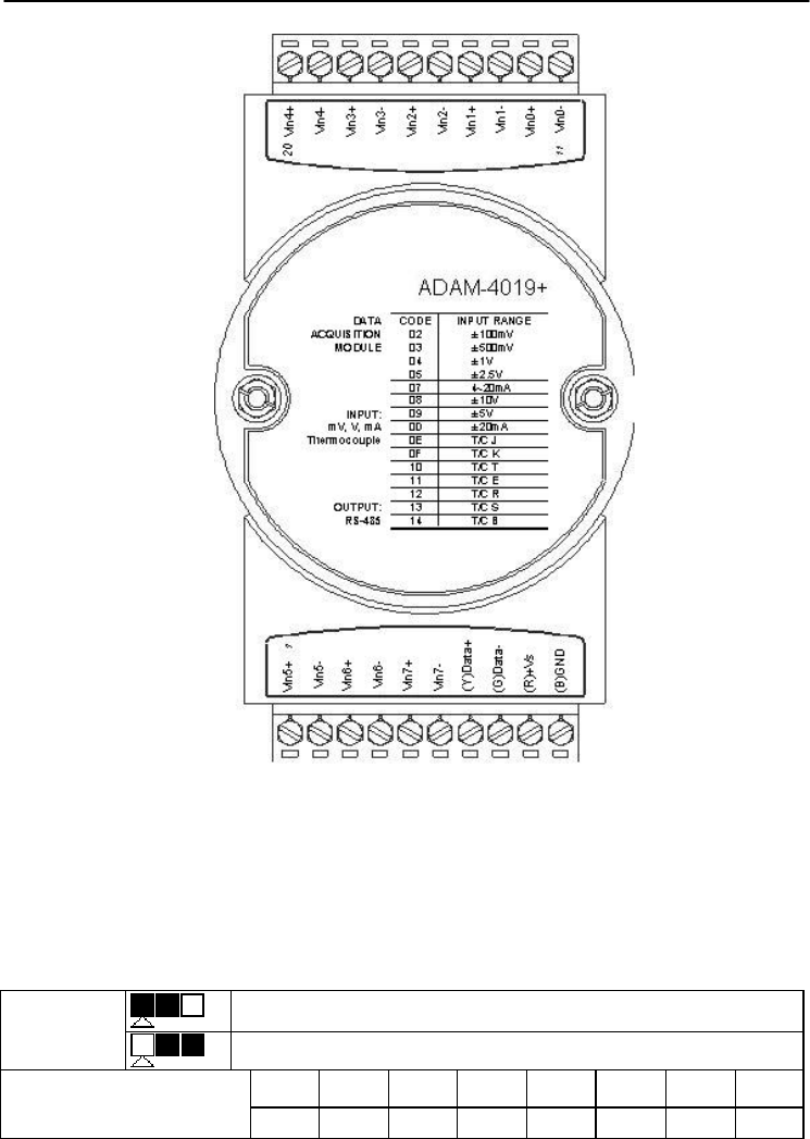
3.8 ADAM-4019+ 8-channel Universal Analog Input Module
The ADAM-4019+ is universal analog input module to integrate
with various AI modules into one. It not only reduces the hardware cost,
but also simplifies the wiring complexity. Furthermore, the ADAM-
4019+ provides the burnt-out detection functionality for 4~20mA and
all thermocouple input.
I/O Modules
3-
38
ADAM 4000 Series User’s Manual
Figure 3-34 ADAM-4019+ 8-channel Universal Analog Input
The jumper setting of ADAM-4019+ for input type selection:
JP0~JP7 20mA Input Range
Voltage Input range
Mapping to Channel Ch.0 Ch.1 Ch.2 Ch.3 Ch.4 Ch.5 Ch.6 Ch.7
JP 0 JP 1 JP 2 JP 3 JP 4 JP 5 JP 6 JP 7
*It is built the 120Ω resister inside under current input mode
Chapter 3
Chapter 3 I/O Modules
3-39
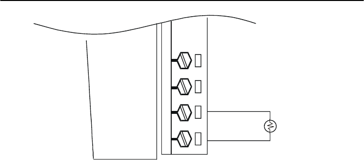
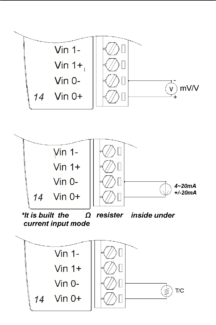
Application Wiring
Figure 3-35 ADAM-4019+ Universal Analog Input Wiring Diagram
120

I/O Modules
3-
40
ADAM 4000 Series User’s Manual
Technical specification of ADAM-4019+
Channel 8
Resolution 16 bits
Input Type V, mV, mA, T/C
Input type and temperature range V: ±1 V , ±2.5 V, ±5 V , ±10 V
mV: ±100 mV , ±500 mV
mA: ±20 mA (with 120 Ω resister)
4~20mA (with 120 Ω resister)
Thermocouple:
J 0 to 760 °C
K 0 to 1370 °C
T -100 to 400 °C
E 0 to 1000 °C
R 500 to 1750 °C
S 500 to 1750 °C
B 500 to 1800 °C
Isolation Voltage 3000 VDC
Sampling Rate 10 samples/sec (total)
Input Impedance Voltage: 20 M, Current: 120
Accuracy ±0.1% or better
Power Consumption 1.0W @ 24VDC
I/O Connector Type 10 pin plug-in terminal
Burn-out Detection 4~20mA and all thermocouple input
Table 3-5 Technical specification of ADAM-4019+

Chapter 3
Chapter 3 I/O Modules
3-41
3.9 ADAM-4021 Analog Output Module
Analog output module receives its digital input through an RS-485
interface from the host computer. The format of the data is either two’s
complement hexadecimal format or percentage of full-scale range
(FSR), depending on the module’s configuration. It then uses its
microprocessor-controlled D/A converter to convert the digital data into
output signals.
You will get a true read-back of the analog output signal from the
unit’s ADC, which monitors the output independently. You can also
specify slew rates and start up currents through the configuration
software. The Analog Output Module can supply single-channel analog
output in a range of voltages or currents.
Furthermore, it will protect your equipment from power surges at
the ground terminal by providing opto-isolation of the D/A output and
up to 3000 VDC transformer based isolation.
Slew Rate
The slew rate is defined as the discrepancy between the present
number of milliamps (or Volts) per second and the required output
currents (or voltages). An ADAM analog output module may be
configured for a specific slew rate.
I/O Modules
3-
42
ADAM 4000 Series User’s Manual
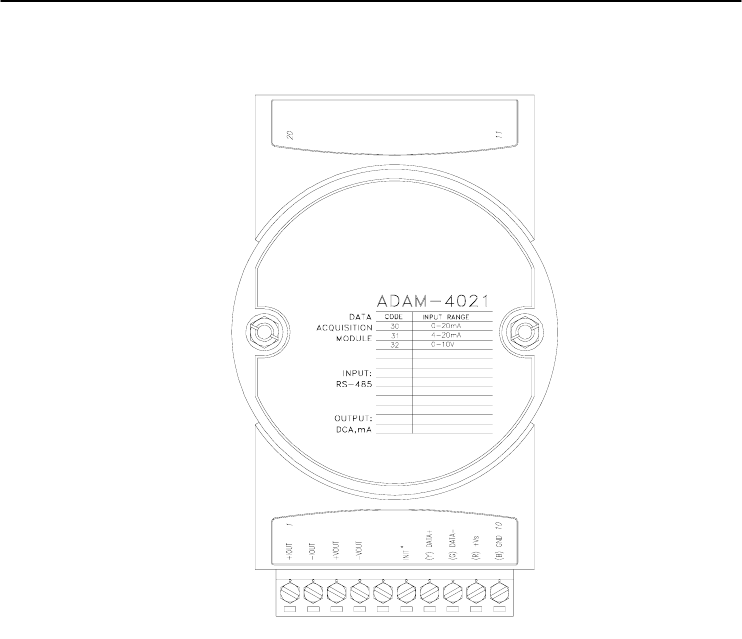
ADAM-4021 Analog Output Module
Figure 3-36 ADAM -4021 Analog Output Module
Depending on its configuration settings the module accepts the
following formats from the host computer:
- Engineering units
- Percent of full-scale range (FSR)
- Two’s complement hexadecimal format,
Output types:
- Voltage: 0 ~ 10 V
(Slew rate: 0.0625 to 64 V/sec)
- Currents: 0 ~ 20 mA, or 4 ~ 20 mA.
(Slew rate: 0.125 to 128 mA/sec)
Chapter 3
Chapter 3 I/O Modules
3-43
Application Wiring
Figure 3-37 ADAM-4021 Analog Output Wiring Diagram
I/O Modules
3-
44
ADAM 4000 Series User’s Manual
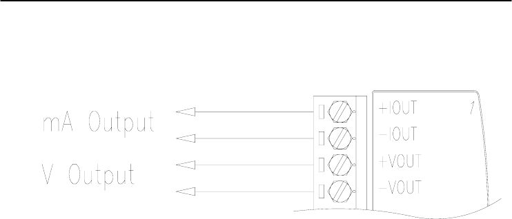
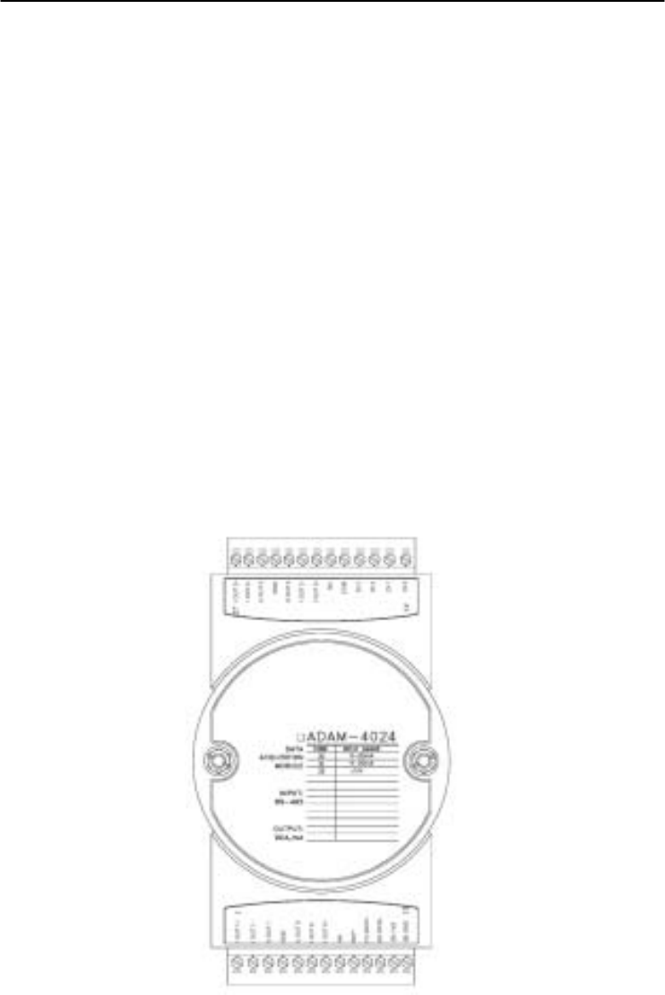
3.10 ADAM-4024 4-channel Analog Output Module
ADAM-4024 is a 4-channel analog output module with mixed type
I/O. Currently, there is not any ADAM-4000 series module that provides
more than one analog output channel. Under some circumstances, it is,
however, a demand for multiple analog outputs to fulfill particular
applications without many duplicate modules. ADAM-4024 is designed
to achieve this purpose by integrating four A/O channels and four
isolated D/I channels into only one module. The four digital input
channels function as an interlock for emergency latch output.
ADAM-4024 inherited from ADAM-4021, but provide multi-range
AO support, allows its four A/O channels working at the same time with
different and more output ranges. For example, it can have 4~20 mA and
±10 V at its output. To ensure the operation of machines and facilities,
ADAM-4024 has the functionality of slew rate control. Output slope is
programmable through ramping/clamping the slew rate. Unlike
traditional mechanism, ADAM-4024 permits users to substitute its
default value at the start up. Users can easily set up and configure the
module to be more adaptive.
Figure 3-38 ADAM-4024 4-channel Analog Output Module

Chapter 3
Chapter 3 I/O Modules
3-45
Technical specification of ADAM-4024
• Resolution: 12-bit
• Output Type: mA, V
• Output Range: 0~20 mA, 4~20 mA, and ±10V
• Isolation Voltage: 3000 VDC
• Output Impedance: 0.5 Ω
• Accuracy:
±0.1% of FSR for current output
±0.2% of FSR for voltage output
• Zero Drift:
Voltage output: ±30 µV/°C
Current output: ±0.2 µA/°C
• Span Temperature Coefficient: ±25 ppm/°C
• Output Slope Rate:
0.125 ~ 128 mA/sec.
0.0625 ~ 64 V/sec.
• Current Load Resistor: 0 to 500
• Built-in Watchdog Timer
• Isolation Digital Input
Channel: 4
Level 0: +1V max
Level 1: +10~30 VDC
I/O Modules
3-
46
ADAM 4000 Series User’s Manual
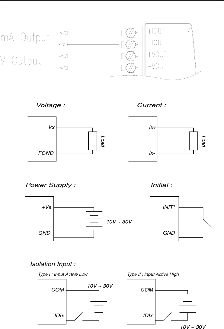
Application Wiring
Figure 3-39 ADAM-4024 Pin Define and Wiring Diagram
Chapter 3
Chapter 3 I/O Modules
3-47
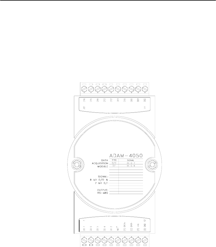
3.11 ADAM-4050 Digital I/O Module
The ADAM-4050 features seven digital input and eight digital
output channels. The outputs are open-collector transistor switches that
you can control from the host computer. You can also use the switches
to control solid-state relays, which can be applied to equipments such as
heaters and pumps. The host computer can use the module's digital
inputs to determine the states of limit, safety switches, and remote
digital signals.
Figure 3-40 ADAM-4050 Digital I/O Module
Channels:
- 7 input channels
- 8 output channels
Digital Input:
- Logic level 0: +1 V max.
- Logic level 1: +3.5 ~ 30 V
Digital Output:
- Open collector to 30 V, 30 mA max. load
I/O Modules
3-
48
ADAM 4000 Series User’s Manual
Application Wiring
Figure 3-41 ADAM-4050 TTL Input Wiring Diagram
Figure 3-42 ADAM-4050 Contact Closure Input Wiring Diagram
Figure 3-43 ADAM-4050 Digital Output Wiring Diagram Used with SSR
Chapter 3
Chapter 3 I/O Modules
3-49
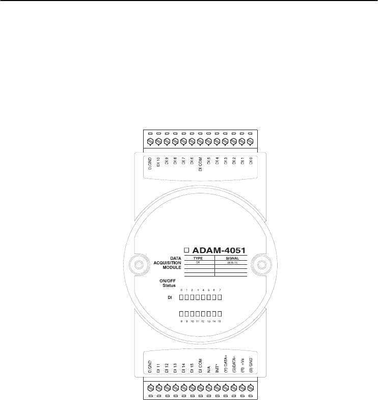
3.12 ADAM-4051 16-channel Isolated Digital Input Module
The ADAM-4051 is a 16 channel Digital Input Module. It is built
with 2500VDC optical isolation, and it is suitable for critical applications.
The main difference from other modules is that ADAM-4051 accepts
10 ~ 50V input voltage to fit various digital signals like 12 V, 24 V, and
48 V. Moreover, users can read the current status from the LED
indicators on the front panel.
Figure 3-44 ADAM-4051 16-channel Isolated Digital Input Module
• Channel: 16 (4-channel/group)
• Optical Isolation: 2500 VDC
• Opto-isolator response time: 25 s
• Over-voltage Protect: 70 VDC
• ESD (Electro Static Discharge): 2000 VDC
• LED Indicator: On: Active; Off: Non-active
• Input Voltage:
Dry Contact Logic level 1: close to GND, Logic level 0: open
Wet Contact Logic level 1: 10 ~ 50 V, Logic level 0: 3 V
• Power consumption: 1W @ 24 VDC
• I/O Connector Type: 13 pin plug-in terminal*2
I/O Modules
3-
50
ADAM 4000 Series User’s Manual
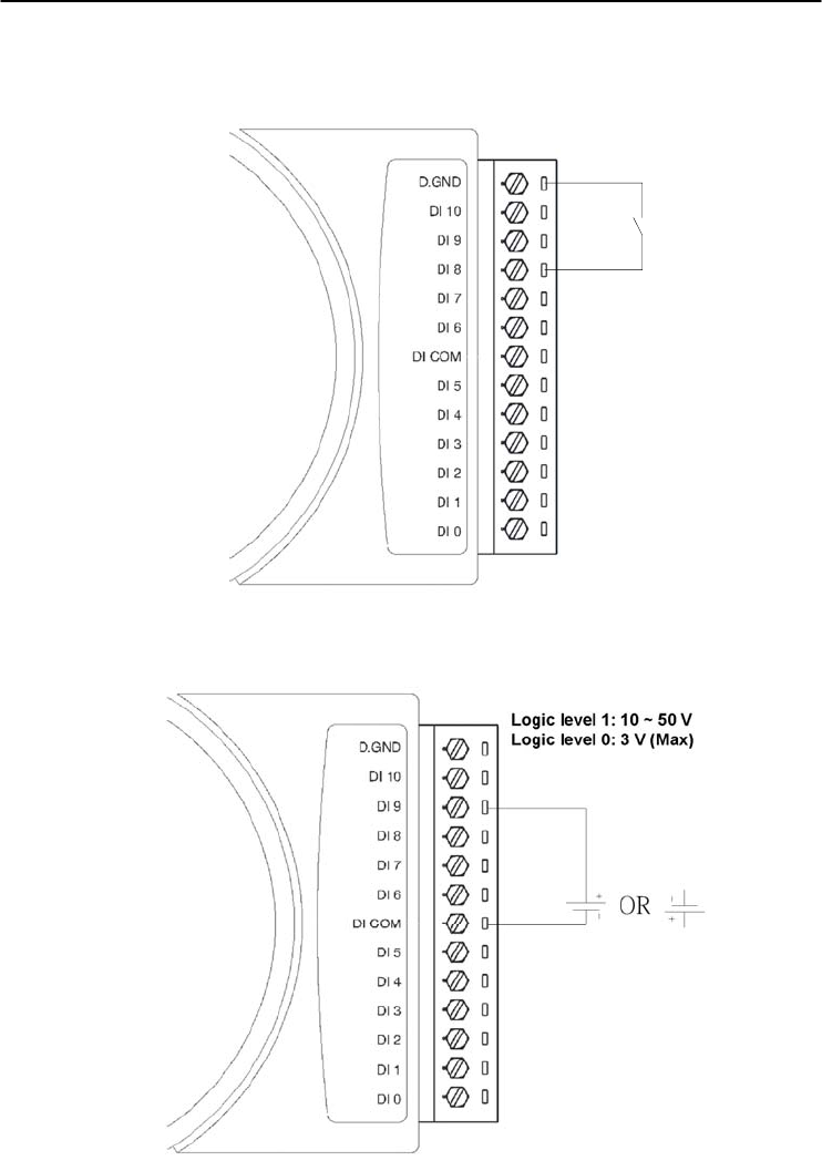
Application Wiring
Figure 3-45 ADAM-4051 Dry Contact Wiring Diagram
Figure 3-46 ADAM-4051 Wet Contact Wiring Diagram
Chapter 3
Chapter 3 I/O Modules
3-51
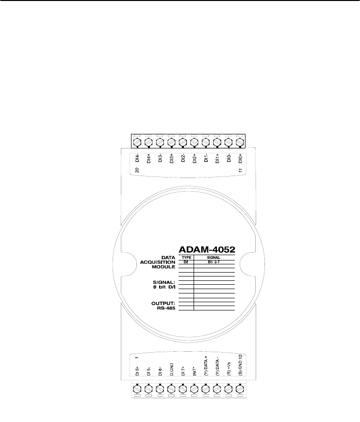
3.13 ADAM-4052 Isolated Digital Input Module
The ADAM-4052 provides eight digital input channels. Among
these eight channels, six of them are fully independent isolated
channels and the other two are isolated channels with a common ground.
They all have 5000 VRMS isolation to prevent power surges from the
input lines
Figure 3-47 ADAM-4052 Isolated Digital Input Module
Channels: 8
- 6 differential channels (fully independent isolated channels)
- 2 single-ended channels (isolated channels with common ground)
Digital Input:
- Logic level 0: +1 V max.
- Logic level 1: +3 ~ 30 V
I/O Modules
3-
52
ADAM 4000 Series User’s Manual
Application Wiring
Figure 3-48 ADAM-4052 Isolation Digital Input Wiring Ground
External
Internal
Chapter 3
Chapter 3 I/O Modules
3-53
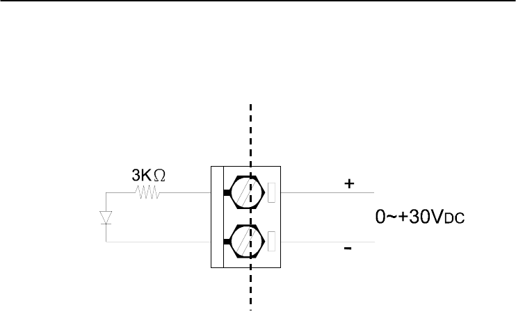
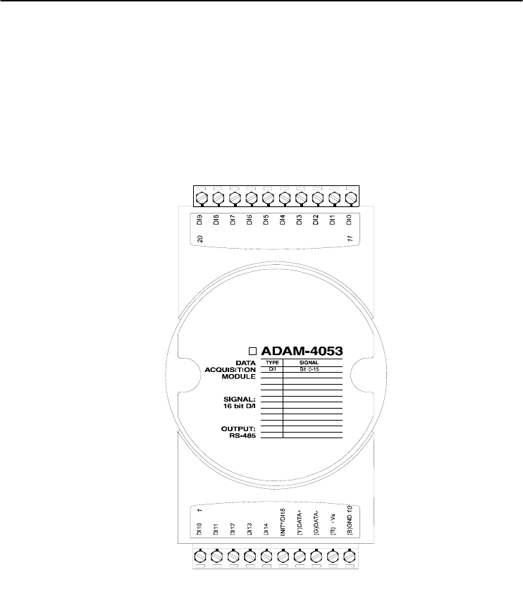
3.14 ADAM-4053 16-channel Digital Input Module
The ADAM-4053 provides 16 digital input channels for dry contact
or wet contact signals. For dry contact, the effective distance from DI
to contact point is up to 500 m.
Figure 3-49 ADAM-4053 16-channel Digital Input Module
Channels: 16 Digital Input
-Dry contact
Logic level 0: Close to GND
Logic level 1: OPEN
-Wet contact
Logic level 0: +2 V max.
Logic level 1: +4 V to +30 V
I/O Modules
3-
54
ADAM 4000 Series User’s Manual
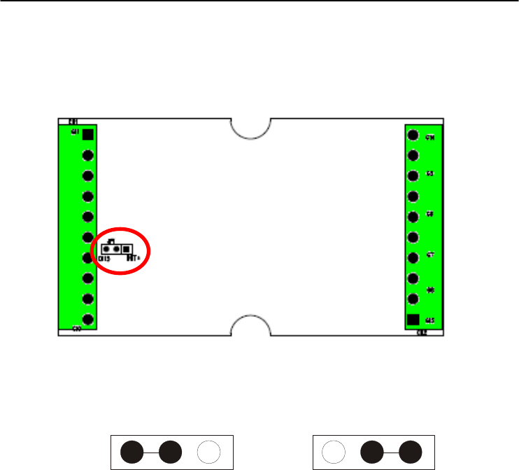
Note: There is one pin showing “INIT*/DI15” on the connector of the
ADAM-4053 module. You can configure the pin define by the jumper on
PCB (refer to the image below to see its location):
Jumper Setting:
DI15 INIT* DI15 INIT
*
DI15 INIT*
Chapter 3
Chapter 3 I/O Modules
3-55
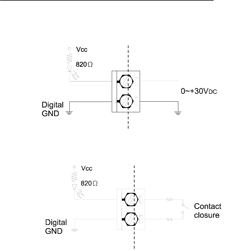
Application Wiring
Figure 3-50 ADAM-4053 Wet Contact Input Wiring Diagram
Figure 3-51 ADAM-4053 Contact Closure Input Wiring Diagram
External
Internal
External
Internal
I/O Modules
3-
56
ADAM 4000 Series User’s Manual
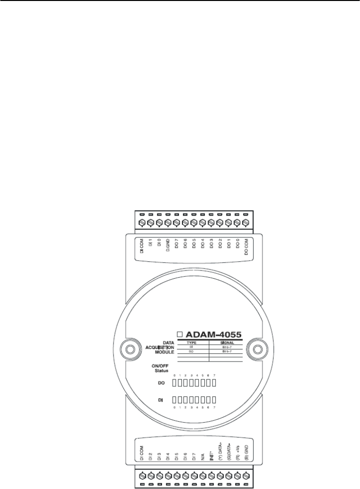
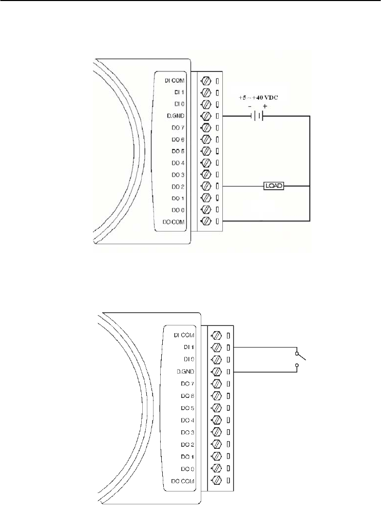
3.15 ADAM-4055 16-channel Isolated Digital I/O Module
The ADAM-4055 offers 8 channel isolated digital input and 8
channel isolated digital output for critical applications. The inputs
accept 10~50 V voltage, and the outputs can supply 5~40 VDC at the
open collector. The ADAM-4055 is user friendly with built LED
indicator for status reading.
Notice: we had updated the digital input dry/wet contact option by
using jumper selection. The default setting is to support these two DI
contacts both at the same time. However, a customer can also choose
his or her needs by supporting only one. Please refer to the following
wiring illustration figure 3-54b for more details
Figure 3-52 ADAM-4055 16-channel Digital I/O Module
Chapter 3
Chapter 3 I/O Modules
3-57
Application Wiring:
Figure 3-53 ADAM-4055 Digital Output Wiring Diagram
Figure 3-54a ADAM-4055 Digital Input Dry Contact Wiring Diagram
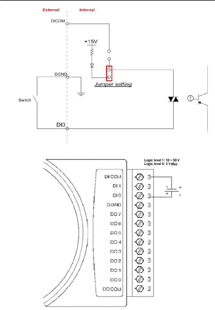
I/O Modules
3-
58
ADAM 4000 Series User’s Manual
Figure 3-54b ADAM-4055 Digital Input Dry Contact Diagram (Internal)
Figure 3-55a ADAM-4055 Digital Input Wet Contact Wiring Diagram
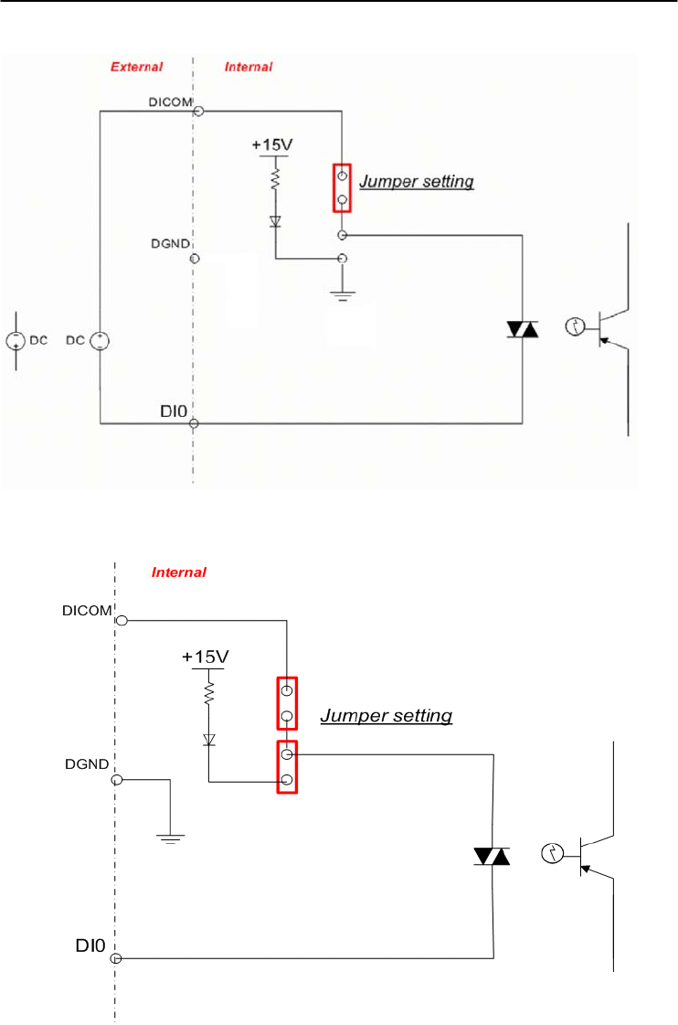
Chapter 3
Chapter 3 I/O Modules
3-59
Figure 3-55b ADAM-4055 Digital Input Wet Contact Diagram (Internal)
Figure 3-56a ADAM-4055 Default Jumper Setting for the Digital Input Wiring
(Support dry and wet contact digital input at the same time)
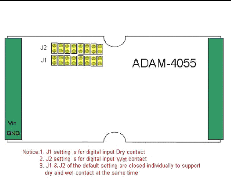
I/O Modules
3-
60
ADAM 4000 Series User’s Manual
Figure 3-56b ADAM-4055 Default Jumper Setting for the Digital Input Wiring
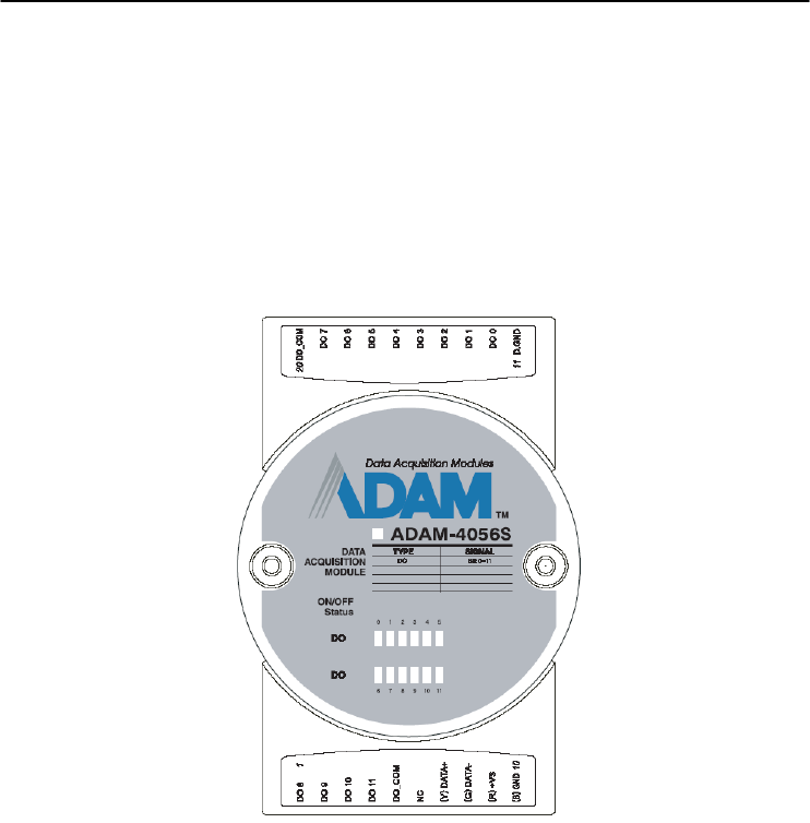
Chapter 3
Chapter 3 I/O Modules
3-61
3.16 ADAM-4056S 12-channel Sink Type Isolated Digital Output
Module
ADAM-4056S is a 12-channel sink type isolated digital output
module. The isolated channels are designed for digital output for
critical applications. Open collector outputs can provide from +5 to
+40 VDC, and both ADAM ASCII and Modbus/RTU protocols are
supported. LED indicators are used for status reading.
Figure 3-57 ADAM-4056S 12-channel Sink Type Isolated Digital Output Module
Technical Specification of ADAM-4056S
Number of Output Channel: 12
Digital Output:
Open Collector from +5 ~ +40V, 200mA max. load (Sink)
LED Indicator: On: Active, Off: Non-active
Power Consumption: 1 W @ 24VDC
Optical isolation: 5000 VDC
Supports Modbus/RTU protocol
I/O Connector Type: 10 pin plug-in terminal*2
Support Safety Value:
Force the DO channels to safety status when communication is in
time-out and over pre-defined period.
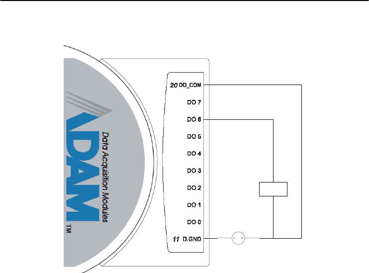
I/O Modules
3-
62
ADAM 4000 Series User’s Manual
Application Wiring
+5V ~ +40V
LOAD
+
-
Figure 3-58 ADAM-4056S Digital Output Wiring Diagram
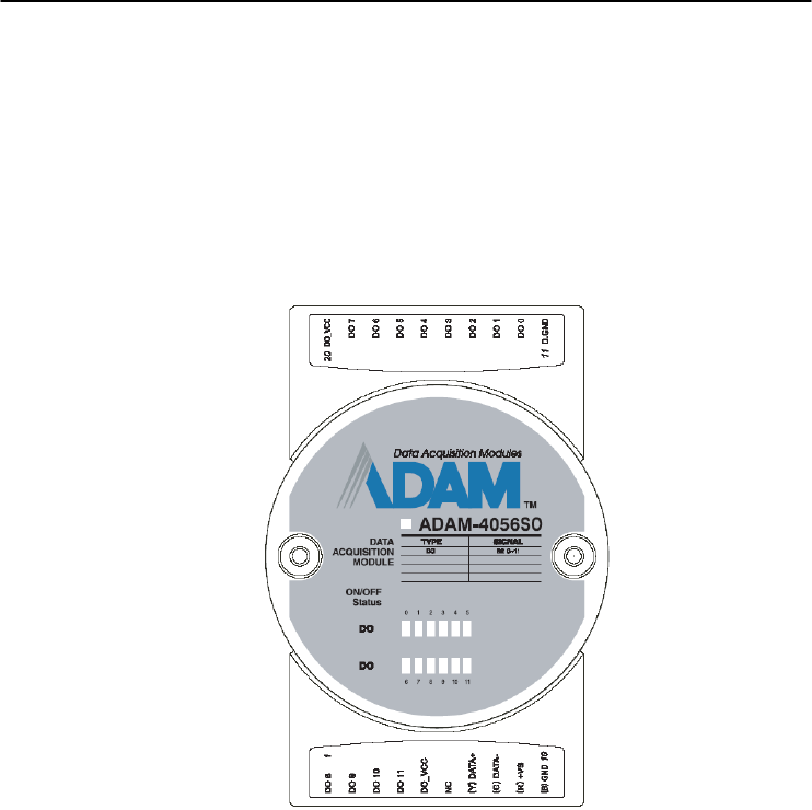
Chapter 3
Chapter 3 I/O Modules
3-63
3.17 ADAM-4056SO 12-channel Source Type Isolated Digital Output
Module
ADAM-4056SO is a 12-channel source type isolated digital output
module. The 12 isolated digital output channels are designed for
critical applications. The digital output signals are sent in the range of
10 ~ 35 VDC with maximum 1A per channel, and both ADAM ASCII
and Modbus/RTU protocols are supported. The LED indicators
provide status reading of the module.
Figure 3-59 ADAM-4056SO 12-channel Source Type Isolated
Digital Output Module
Technical Specification of ADAM-4056SO
Number of Output Channel: 12
Digital Output: VCC: +10 ~ 35VDC, 1A per Channel ( Source)
LED Indicator: On: Active, Off: Non-active
Power Consumption: 1 W @ 24VDC
Optical isolation: 5000 VDC
Supports Modbus/RTU protocol
I/O Connector Type: 10 pin plug-in terminal*2
Leakage current : 50μA
Support Safety Value:
Force the DO channels to safety status when communication is in
time-out and over pre-defined period.
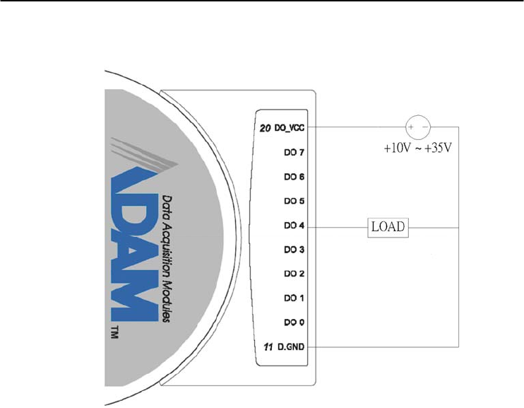
I/O Modules
3-
64
ADAM 4000 Series User’s Manual
Application Wiring
Figure 3-60 ADAM-4056SO Digital Output Wiring Diagram
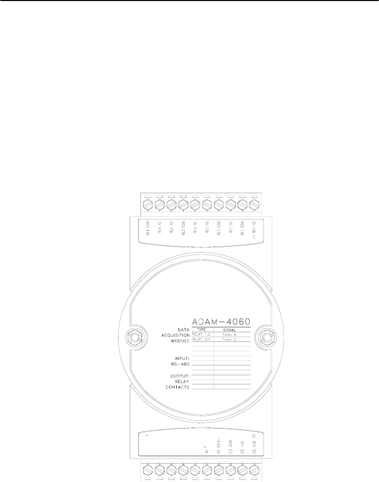
Chapter 3
Chapter 3 I/O Modules
3-65
3.18 ADAM-4060/4068 Relay Output Module
The ADAM Relay Output Module is a low-cost alternative to SSR
modules. The ADAM-4060 Relay Output Module provides four relay
channels; two of them are Form A, and two are Form C. The ADAM-
4068 Relay Output Module provides eight channels. Four of the
channels are Form A, and four are Form C. These two modules are
excellent for ON/OFF control or low-power switching applications and
they are able to support the safety value setting.
ADAM-4060 4-channel Relay Output Module
Figure 3-61 ADAM-4060 4-channel Relay Output Module
Contact rating for Form A and Form C: (Resistive)
AC 0.6 A @ 125 V
0.3 A @ 250 V
DC 2 A @ 30 V
0.6 A @ 110 V
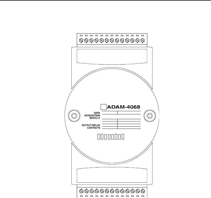
I/O Modules
3-
66
ADAM 4000 Series User’s Manual
ADAM-4068 8-channel Relay Output Module
TYPE SIGNAL
RELAY 0,1,2,3
RELAY 4,5,6,7
FORM A
FORM C
RL4 NO
RL4 COM
RL3 NO
RL3 COM
RL2 NC
RL2 COM
RL2 NO
RL1 NC
RL1 COM
RL1 NO
RL0 NC
RL0 COM
RL0 NO
RELAY
01234567
RL5 NO
RL5 COM
RL6 NO
RL6 COM
RL7 NO
RL7 COM
RL7 NC
NC
INIT*
(Y) DA
T
A+
(G) DA
T
A-
(R) +Vs
(B) GND 10
R E LA Y 3,4 ,5 ,6 F o rm A
R E LA Y 0,1 ,2 ,7 F o rm C
Figure 3-62 ADAM-4068 8-channel Relay Output Module
Contact Rating for Form A and Form C: (Resistive)
AC 125 V @ 0.6 A
250 V @ 0.3 A
DC 30 V @ 2 A
110 V @ 0.6 A
NOTICE: This electric current is under the load of resistance. If
you try to use the load of inductance, the electric current would be
less the above-mentioned value.
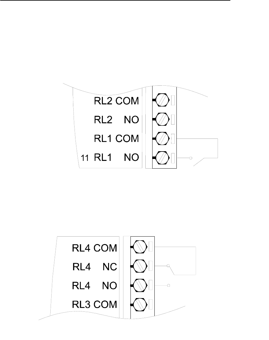
Chapter 3
Chapter 3 I/O Modules
3-67
Application Wiring
The following diagrams are examples of how to connect Form A
and Form C relay output applications to your ADAM modules.
Figure 3-63 ADAM-4060 Form A Relay Output Wiring Diagram
Figure 3-64 ADAM-4060 Form C Relay Output Wiring Diagram
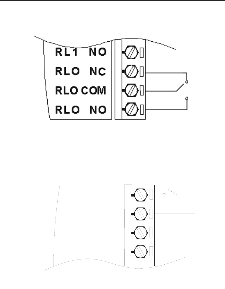
I/O Modules
3-
68
ADAM 4000 Series User’s Manual
Figure 3-65 ADAM-4068 Form C Relay Output Wiring Diagram
RL4 NO
RL4 COM
RL3 NO
RL3 COM
Figure 3-66 ADAM-4068 Form A relay output Wiring Diagram
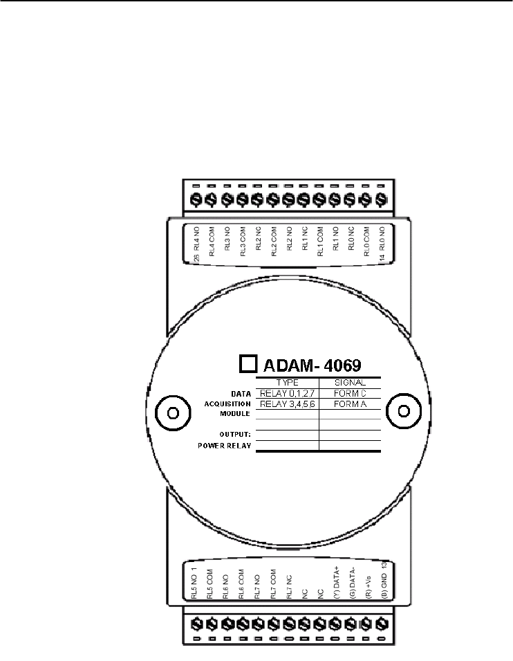
Chapter 3
Chapter 3 I/O Modules
3-69
3.19 ADAM-4069 8-channel Relay Output Module
The ADAM-4069 Relay Output Module provides eight channels; four
are Form A and the rest are Form C. This module is excellent for ON/OFF
control or low-power switching applications.
Figure 3-67 ADAM-4069 Relay Output Module

I/O Modules
3-
70
ADAM 4000 Series User’s Manual
Specification:
z Number of Relay Output Channel: 8
z Digital Output: (Source)
4 Form A , 4 Form C
AC 5A@240V
DC 5A@30V
ON/OFF : 5ms/ 5.6ms
z Power Consumption: 2.2 W
z Supports Modbus/RTU protocol
z I/O Connector Type: 13-pin plug-terminal * 2
z Support Safety Value: Force the DO channels to safety status
when communication is in time-out and over pre-defined period.
Wiring:
Figure 3-68 ADAM-4069 Form C Relay Output
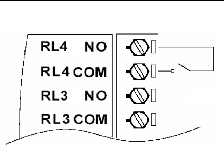
Chapter 3
Chapter 3 I/O Modules
3-71
Figure 3-69 ADAM-4069 Form A Relay Output

I/O Modules
3-
72
ADAM 4000 Series User’s Manual
3.20 ADAM-4080/4080D Counter/Frequency Input Modules
ADAM-4080/4080D Counter/frequency input module has two 32-
bit counter input channels (counter 0 and counter 1) with built-in
programmable timer for frequency measurement. These cost-effective
modules let you monitor counter/frequency data as measurements are
taken.
Front Panel LED Indicator (ADAM-4080D only)
The 5-digit LED display of the ADAM-4080D lets you monitor its
counter data right at the source. The module's LED display shows
counter values as well as high-low alarm messages when the counter
exceeds its programmed limits (direct display).
Another option is to display the data sent by the host computer. The
module first sends counter data to the host computer for conversion or
calculation. The host computer then sends the data back to the ADAM-
4080D and displays on the module's LED display (remote display).
Signal Input Mode
The ADAM-4080/4080D provides separate terminals for photo
isolated input and non-isolated input to simplify the wiring. Opto-
isolated input provides 2500 VRMS isolation to protect your equipment
from power surges at the ground terminal. After you make the physical
connections, program the module to identify which of its two input
terminals should be activated (isolated or non-isolated terminals).
Programmable Digital Filter
The ADAM-4080/4080D module includes a unique programmable
digital filter to reject noise from the input lines. You can specify
separate time constant like minimum signal width at high level and
minimum signal width at low level. This provides stable output
readings.
Programmable Threshold
When the ADAM-4080/4080D is programmed for non-isolated
input, you can set a high and low trigger level. Like the programmable
digital filter, the programmable threshold rejects noise from the input
lines and provides a stable input readings

Chapter 3
Chapter 3 I/O Modules
3-73
External Control (Gate mode)
Aside from the GND and counter terminal, each channel has a gate
terminal to connect to an external gate signal. The gate signal (high or
low) can trigger the counter from start or stop counting. The gate mode
can be among these three options, low, high or disabled (low means that
counting starts when the gate signal is low. It stops once the gate signal
becomes high)
Programmable Alarm Output
The ADAM-4080 module provides a configurable alarm for each
counter. The ADAM-4080D provides high and low alarm functions for
counter 0. When the counter reaches an alarm limit, it will trigger the
built-in digital output of machine ON/OFF control. The alarm limits
may be downloaded into the module's EEPROM by the host computer.
The initial count value of ADAM-4080 module's counter can be
configured in any values.
The alarm functions can be enabled or disabled remotely. When the
alarm functions are enabled, digital output channels are used to indicate
the alarm states. For ADAM-4080, digital output channel 0 equals to
the alarm state of counter 0, and digital output channel 1 equals to the
alarm state of counter 1. For ADAM-4080D, digital output channel 0
equals to the low alarm state of counter 0, and digital output channel 1
equals to the high alarm state of counter 0.
Every A/D conversion will be followed by a comparison of alarm
limits. If the input value exceeds one of these limits, the corresponding
alarm state is set to ON.
There are two alarm mode options, momentary and latching, for
ADAM-4080D. If the alarm is in latching mode, the alarm will stay on
even when the input value returns within the limits. An alarm in
latching mode can be turned off by issuing a Clear Alarm command
from the host computer. A latching alarm is cleared by the module
when the opposite alarm is set. For example, the alarm is in latching
mode and the high alarm is then turned ON. When the module receives
a value that is lower than the low alarm limit, it will clear the high
alarm and turn the low alarm ON.
When the alarm is in Momentary mode, the alarm will be turned
OFF as soon as the input value returns within the limits.
The arrangement of coupling high and low alarm states with digital
output lines may be utilized to build ON/OFF controllers that can
operate without the host computer involvement.
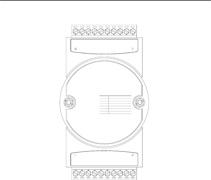
I/O Modules
3-
74
ADAM 4000 Series User’s Manual
ADAM-4080 Counter/Frequency Input Modules
ADAM-4080
CODE INPUT RANGE
50
51
DATA
ACQUISITION
MODULE
GATE 1-
GATE 1+
IN 1-
IN 0
GATE 0
D.GND
INIT*
(Y) DATA+
(G) DATA-
(R) +Vs
(B) GND
IN 1+
DO 0
DO 1
IN 1
COUNTER
FREQUENCY
GATE 1
IN 0+
IN 0-
GATE 0+
GATE 0-
(Non-isolation)
Figure 3-70 ADAM-4080 Counter/Frequency Input Module
Channels: 2 independent 32-bit counters (counter 0 and counter 1)
Input frequency: 50 kHz max.
Input mode: Isolated or non-isolated
Isolation input level:
- Logic level 0: +1 V max
- Logic level 1: +3.5 V to +30 V
- Input Impedance: 1.2 kΩ
Non-isolation input level (programmable threshold):
- Logic level 0: 0 to +5V (default = 0.8 V)
- Logic level 1: 0 to +5V (default = 2.4 V)
- Input Impedance: 50 MΩ
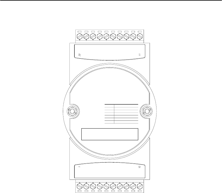
Chapter 3
Chapter 3 I/O Modules
3-75
ADAM-4080D Counter/Frequency Input Modules with LED Display
ADAM-4080D
CODE INPUT RANGE
50
51
DATA
ACQUISITION
MODULE
GATE 1-
GATE 1+
IN 1-
IN 0
GATE 0
D.GND
INIT*
(Y) DATA+
(G) DATA-
(R) +Vs
(B) GND
IN 1+
DO 0/LO
DO 1/HI
IN 1
COUNTER
FREQUENCY
GATE 1
IN 0+
IN 0-
GATE 0+
GATE 0-
(Non-isolation)
(Photo-isolation)
Figure 3-71 ADAM-4080D Counter/Frequency Input Module
with LED Display
Channels: 2 independent 32-bit counters (counter 0 and counter 1)
Input frequency: 50 kHz max.
Input mode: Isolated or non-isolated
Isolation input level:
- Logic level 0: +1 V max
- Logic level 1: +3.5 V to +30 V
- Input Impedance: 1.2 kΩ
Non-isolation input level (programmable threshold):
- Logic level 0: 0 to +5V (default = 0.8 V)
- Logic level 1: 0 to +5V (default = 2.4 V)
- Input Impedance: 50 MΩ
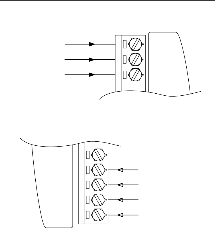
I/O Modules
3-
76
ADAM 4000 Series User’s Manual
Application Wiring
Counter Input
GATE0
IN0
1
D.GND
Gate Control
GND
Figure 3-72 ADAM-4080/4080D Non-isolated Input
GATE1+
GATE1-
11
IN1-
IN1+ +
-
+
-
Counter Input
GATE Control
Figure 3-73 ADAM-4080/4080D Photo-isolated Input
Command Set 4

Command Set
4-
2
ADAM 4000 Series User’s Manual
4.1 Introduction
In order to avoid communication conflicts among devices trying to send
data simultaneously, all the traffics are coordinated by the host
computer. This action is initiated by the host computer using a
command/response protocol.
When the modules are not transmitting, they are in listening mode. The
host issues a command to a module with a specified address and waits
for the module’s response. If there is no response, a timeout aborts the
sequence and returns the control to the host.
Changing ADAM’s configuration might require the module to perform
auto calibration before changes may take effect. This is the case when
the range is modified especially. The module has to perform all stages
of auto calibration which is also performed during the start up. When
the calibration process is underway, the module does not respond to any
other commands. The command set in the following pages includes the
exact delays that might occur as modules are reconfigured.
4.2 Syntax
[delimiter character][address][command][data][checksum] [carriage
return]
Every command begins with a delimiter character. There are four valid
characters: a dollar sign $, a pound sign #, a percentage sign % and an
at sign @.
The delimiter character is followed by a two-character address
(hexadecimal) that specifies the target module. The actual
two-character command follows by the address. Depending on the
command, an optional data segment may follows by a command string.
Furthermore, an optional two-character checksum may be appended to
the total string. Every command is terminated by a carriage return (cr).
ALL COMMANDS SHOULD BE ISSUED IN UPPERCASE
CHARACTERS!

Chapter 4
Chapter 4 Command Set
4-3
Before the command set is given, we provide an I/O module commands
search table to help you find the commands that you wish to use. The
command set is divided into the following three categories:
• Analog Input Module commands
• Analog Output Module commands
• Digital I/O, Relay Output and Counter/Frequency Module
commands
Each Category starts with a command summary of a particular type of
module. However, they are explained in more depth at Chapter 5, 6 & 7
with detailed datasheets of each individual commands.
Although commands in different subsections sometimes share the same
format, the effect they have on a certain module can be completely
different from others. For example, the configuration command
%AANNTTCCFF affects analog input modules and analog output
modules differently. The full command set for every module is listed
below.

Command Set
4-
4
ADAM 4000 Series User’s Manual
4.3 I/O Module Commands Search Table
ADAM-4011 Command Table
Command Syntax
Command Name Command Description Page No.
%AANNTTCCFF Configuration Sets the address, input range,baud
rate, data format, checksum
status, and/or integration time for a
specified analo
g
input module
5-4
$AA2 Configuration Status Returns the configuration
parameters for the specified
analo
g
input module
5-10
$AAF Read Firmware
Version Return the firmware version code
from the specified analog input
module
5-12
$AAM Read Module Name Return the module name from the
specified analo
g
input module
5-13
#AA Analog Data In Returns the input value from a
specified analog input module in
the currently configured data
format
5-14
$AA0 Span Calibration Calibrates an analog input module
to correct for gain errors 5-19
$AA1 Offset Calibration Calibrates an analog input module
to correct for offset errors
5-20
#** Synchronized
Sampling Orders all analog input modules to
sample their input values and store
them in special registers
5-21
$AA4 Read Synchronized
Data Returns the value that was stored
in the specified module's register
after the #** command
5-22
$AA3 CJC Status Returns the value of the CJC
sensor for a specified analog input
module
5-25
$AA9SNNNN CJC Offset
Calibration Calibrates the CJC sensor for
offset errors 5-26
(Continued on following page)

Chapter 4
Chapter 4 Command Set
4-5
ADAM-4011 Command Table (Continued)
Command Syntax
Command Name Command Description Page No.
@AADI Read Digital I/O and
Alarm Status The addressed module returns the
state of its digital input channel, its
two digital output channels and the
status of its alarm
5-50
@AADO(data) Set Digital Output Set the values of the module's two
di
g
ital outputs
(
ON or OFF
)
5-52
@AAEAT Enable Alarm Enables the alarm in either
Momentary or Latching mode 5-54
@AAHI(data) Set High Alarm Downloads the High alarm limit
value
5-56
@AALO(data) Set Low Alarm Downloads the Low alarm limit
value 5-57
@
AADA Disable Alarm
Disables all alarm functions
5-58
@
AACA Clear Latch Alarm
The latch alarm is reset
5-59
@AARH Read High Alarm The addressed analog input
module is asked to return its high
alarm value
5-60
@AARL Read Low Alarm The addressed analog input
module is asked to return its low
alarm value
5-61
@AARE Read Event Counter The addressed module is asked to
return its event counter value 5-62
@AACE Clear Event Counter The event counter is set to 0 5-63

Command Set
4-
6
ADAM 4000 Series User’s Manual
ADAM-4011D Command Table
Command S
y
ntax
Command Name
Command Description
Pa
g
e No.
%AANNTTCCFF Configuration Sets the address, input range,baud
rate, data format, checksum
status, and/or integration time for a
specified analog input module
5-4
$AA2 Configuration Status Returns the configuration
parameters for the specified
analo
g
input module
5-10
$AAF Read Firmware
Version Return the firmware version code
from the specified analog input
module
5-12
$AAM Read Module Name Return the module name from the
specified analo
g
input module
5-13
#AA Analog Data In Returns the input value from a
specified analog input module in
the currently configured data
format
5-14
$AA0 Span Calibration Calibrates an analog input module
to correct for gain errors 5-19
$AA1 Offset Calibration Calibrates an analog input module
to correct for offset errors
5-20
#** Synchronized
Sampling Orders all analog input modules to
sample their input values and store
them in special re
g
isters
5-21
$AA4 Read Synchronized
Data Returns the value that was stored
in the specified module's register
after the #** command
5-22
$AAB Open Thermocouple
Detection Ask the module to respond
whether the thermocouple is open
or not
5-24
$AA3 CJC Status Returns the value of the CJC
sensor for a specified analog input
module
5-25
$AA9SNNNN CJC Offset
Calibration
Calibrates the CJC sensor for
offset errors
5-26
(Continued on following page)

Chapter 4
Chapter 4 Command Set
4-7
ADAM-4011D Command Table (Continued)
Command Syntax Command Name Command Description Page No.
@AADI Read Digital I/O and
Alarm Status The addressed module returns the
state of its digital input channel, its
two digital output channels and the
status of its alarm
5-50
@AADO(data) Set Digital Output Set the values of the module's two
di
g
ital outputs
(
ON or OFF
)
5-52
@AAEAT Enable Alarm Enables the alarm in either
Momentary or Latching mode 5-54
@AAHI(data) Set High Alarm Downloads the High alarm limit
value
5-56
@AALO(data) Set Low Alarm Downloads the Low alarm limit
value 5-57
@
AADA Disable
A
larm
Disables all alarm functions
5-58
@
AACA Clear Latch Alarm
The latch alarm is reset
5-59
@AARH Read High Alarm The addressed analog input
module is asked to return its high
alarm value
5-60
@AARL Read Low Alarm The addressed analog input
module is asked to return its low
alarm value
5-61
@AARE Read Event Counter The addressed module is asked to
return its event counter value 5-62
@AACE Clear Event Counter The event counter is set to 0 5-63

Command Set
4-
8
ADAM 4000 Series User’s Manual
ADAM-4012 Command Table
Command S
y
ntax
Command Name
Command Description
Pa
g
e No.
%AANNTTCCFF Configuration Sets the address, input range,baud
rate, data format, checksum
status, and/or integration time for a
specified analo
g
input module
5-4
#AA Analog Data In Returns the input value from a
specified analog input module in
the currently configured data
format
5-14
$AA0 Span Calibration Calibrates an analog input module
to correct for
g
ain errors
5-19
$AA1 Offset Calibration Calibrates an analog input module
to correct for offset errors 5-20
#** Synchronized
Sampling Orders all analog input modules to
sample their input values and store
them in special re
g
isters
5-21
$AA4 Read Synchronized
Data Returns the value that was stored
in the specified module's register
after the #** command
5-22
$AA2 Configuration Status Returns the configuration
parameters for the specified
analog input module
5-10
$AAF Read Firmware
Version Return the firmware version code
from the specified analog input
module
5-12
$AAM Read Module Name Return the module name from the
specified analog input module 5-13
(Continued on following page)

Chapter 4
Chapter 4 Command Set
4-9
ADAM-4012 Command Table (Continued)
Command S
y
ntax
Command Name
Command Description
Pa
g
e No.
@AADI Read Digital I/O and
Alarm Status The addressed module returns the
state of its digital input channel, its
two digital output channels and the
status of its alarm
5-50
@AADO(data) Set Digital Output Set the values of the module's two
di
g
ital outputs
(
ON or OFF
)
5-52
@AAEAT Enable Alarm Enables the alarm in either
Momentary or Latching mode 5-54
@AAHI(data) Set High Alarm Downloads the High alarm limit
value 5-56
@AALO(data) Set Low Alarm Downloads the Low alarm limit
value
5-57
@AADA Disable Alarm Disables all alarm functions 5-58
@
AAC
A
Clear Latch Alarm
The latch alarm is reset
5-59
@AARH Read High Alarm The addressed analog input module
is asked to return its high alarm
value
5-60
@AARL Read Low Alarm The addressed analog input module
is asked to return its low alarm
value
5-61
@AARE Read Event Counter
The addressed module is asked to
return its event counter value
5-62
@AACE Clear Event Counter
The event counter is set to 0 5-63

Command Set
4-
10
ADAM 4000 Series User’s Manual
ADAM-4013 Command Table
Command Syntax
Command Name Command Description Page No.
%AANNTTCCFF Configuration Sets the address, baud rate, data
format, checksum status, and/or
integration time for a specified
analo
g
input module
5-4
#AA Analog Data In Returns the input value from a
specified analog input module in
the currently configured data
format
5-14
$AA0 Span Calibration Calibrates an analog input moudle
to correct for gain errors 5-19
$AA1 Offset Calibration Calibrates an analog input moudle
to correct for offset errors
5-20
#** Synchronized
Sampling Orders all analog input modules to
sample their input values and store
them in special registers
5-21
$AA4 Read Synchronized
Data Returns the value that was stored
in the specified module's register
after the #** command
5-22
$AA2 Configuration Status Returns the configuration
parameters for the specified
analo
g
input module
5-10
$AAF Read Firware
Version Returns the firmware version code
from the specified analog input
module
5-12
$AAM Read Module Name Returns the module name from the
speci
f
ied analo
g
input module
5-13

Chapter 4
Chapter 4 Command Set
4-11
ADAM-4015/ADAM-4015T Command Table
Command
Syntax Command Name
Command Description
Page
No.
%AANNTTCCFF
Configuration
Sets the address, baud rate, data format,
checksum status, and/or integration time for a
specified analog input module
5-4
$AA2 Configuration Status Returns the configuration parameters for the
specified analog input module 5-10
$AAF Read Firmware
Version Return the firmware version code from the
specified analog input module 5-12
$AAM Read Module Name Return the module name from the specified
analog input module 5-13
#AA
A
nalog Data In
Returns the input value from a specified analog
input module in the currently configured data
format
5-14
#AAN Read Analog Input
from Channel N Returns the input value from a specified channel
of analog input module in the currently configured
data format
5-16
$AA5VV Enable/Disable
Channels for
Multiplexing
Enable or disable the individual channels in an
analog module 5-17
$AA6 Read Channel
Status Get the enable/disable status of all channels in
an analog module 5-18
#** Synchronized
Sampling Orders all analog input modules to sample their
input values and store them in special registers 5-21
$AA4 Read Synchronized
Data Returns the value that was stored in the specified
module's register after the #** command 5-22
$AAB Channel Diagnose
Diagnose channel status in over range, under
range, and wire opening 5-24
$AA0Ci Single Channel
Span Calibration Calibrates a specified channel to correct for gain
errors 5-27
$AA1Ci Single Channel
Offset Calibration Calibrates a specified channel to correct for offset
errors 5-28
$AA7CiRrr Single Channel
Range Configuration
Configure the input type and range of the
specified channel in an analog input module 5-29
$AA8Ci Read Single
Channel Range
Configuration
Get the input type and range of the specified
channel in an analog input module 5-30
$AAXnnnn Watchdog Timer
Setting Set communication WDT cycle time from 0000 ~
9999 (unit: 0.1 second. if value is 0000, the
communication WDT function will be disable)
5-31
$AAY Read Watchdog
Timer Setting Read the cycle time setting of communication
WDT 5-32
$AAS0 Internal Calibration
Internal sel
f
-calibration for offset and
gain errors 5-33
$AAS1 Reload default
calibrating
parameter
Reload factory default calibrating parameter to
overwrite current calibrating parameter 5-34

Command Set
4-
12
ADAM 4000 Series User’s Manual
ADAM-4016 Command Table
Command Syntax
Command Name Command Description Page No.
%AANNTTCCFF Configuration Set the address, input range, baud
rate, data format, checksum status
and/or integration time for the
specified analo
g
input module
5-4
$AA2 Configuration Status Return the configuration
parameters for the specified
analo
g
input module
5-10
$AAF Read Firmware
Version Return the firmware version code
from the specified analog input
module
5-12
$AAM Read Module Name Return the module name from the
specified analo
g
input module
5-13
#AA Read Analog Input Return the input value from the
specified analog input module in
the currently configured data
format
5-14
$AA0 Span Calibration Calibrate an analog input module
to correct for
g
ain errors
5-19
$AA1 Offset Calibration Calibrate an analog input module
to correct for offset errors
5-20
#** Synchronized
Sampling Orders all analog input modules to
sample their input values and store
them in special registers
5-21
$AA4 Read Synchronized
Data Returns the value that was stored
in the specified module's register
after the #** command
5-22
$AA6 Get Excitation
Voltage Output Value Returns either last value sent to
specified module by $AA7
command, or start-up output
voltage
5-65
$AA7 Excitation Voltage
Output
Direct output excitation voltage
data to a specified module
5-66
$AAS Start-up Voltage
Output Configuration
Stores a default value in a
specified module. The output value
will take effect upon atartup.
5-67
$AAE Trim Calibration Trims specified module a number
of units up or down 5-69
$AAA Zero Calibration Tells the module to store
paramenters for zero calibration 5-70
$AAB Span Calibration Tells the module to store
parameters for span calibration 5-71
(Continued on following page)

Chapter 4
Chapter 4 Command Set
4-13
ADAM-4016 Command Table (Continued)
Command S
y
ntax
Command Name
Command Description
Pa
g
e No.
@AADI Read Digital I/O And
Alarm Status Ask the addressed module to return
the state of its four digital output
channels and the status of its alarm
5-50
@AADO(data) Set Digital Output
Values
Set the values of the module's four
di
g
ital outputs
(
ON or OFF
)
5-52
@AAEAT Enable Alarm Enable the alarm in either
monentary or latching mode 5-54
@
AAHI
(
data
)
Set Hi
g
h Alarm Value Download the hi
g
h alarm limit value 5-56
@
AALO
(
data
)
Set Low Alarm Value
Download the low alarm limit value 5-57
@AADA Disable Alarm Disable all alarm functions 5-58
@AACA Clear Latch Alarm Reset the module's latch alarm to
zero
5-59
@AARH Read High Alarm
Value Ask the addressed module to return
its high alarm value 5-60
@AARL Read Low Alarm
Value
Ask the addressed module to return
its low alarm value
5-61

Command Set
4-
14
ADAM 4000 Series User’s Manual
ADAM-4017 Command Table
Command Syntax
Command Name Command Description Page No.
%AANNTTCCFF Configuration Set the address, input range, baud
rate, data format, checksum status
and/or integration time for the
specified analo
g
input module
5-4
$AA2 Offset Calibration Return the configuration
parameters for the specified
analo
g
input module
5-9
$AAF Read Channel Status
Return the firmware version code
from the specified analog input
module
5-11
$AAM Read Version Return the module name from the
specified analo
g
input module 5-12
#AA from Channel N Return the input values from all
channels of the specified analog
input module
5-13
#AAN Read Analog Input Return the input value from
channels number N of the
specified analo
g
input module
5-15
$AA5VV Configuration Status Enables/disables multiplexing
simultaneously for seperate
channels of the specified input
module
5-16
$AA6 Enable/disable
Channels for
Multiplexing
Ask the specified input module to
return the status of all eight
channels
5-17
$AA0 Read Analog Input
from all Channels
Calibrate the analog input module
to correct for
g
ain errors
5-18
$AA1 Span Calibration Calibrate the analog input module
to correct for offset errors
5-19

Chapter 4
Chapter 4 Command Set
4-15
ADAM-4017+ Command Table
Command
S
y
ntax Command Name Command Description Page
No.
%AANNTTCCFF
Configuration Set the address, input range, baud rate,
data format, checksum status and/or
integration time for the specified analog
input module
5-4
$AA2 Configuration
Status
Return the configuration parameters for
the specified analo
g
input module
5-10
$AAF Read Version Return the firmware version code from the
specified analog input module 5-12
$AAM Read the Module
Name
Return the module name from the
specified analo
g
input module
5-13
#AA Read Analog Input
from all Channels Return the input values from all channels
of the specified analo
g
input module 5-14
#AAN Read Analog Input
from Channel N Return the input value from channels
number N of the specified analog input
module
5-16
$AA5VV Enable/disable
Channels for
Multiplexing
Enables/disables multiplexing
simultaneously for seperate channels of
the specified input module
5-17
$AA6 Read Channel
Status
Ask the specified input module to return
the status of all ei
g
ht channels
5-18
$AA0Ci Span Calibration
Gain error calibrate of assignment channel,
User have to input the external standard source
for calibrating process
5-27
$AA1Ci Offset Calibration
Offset error calibrate of assignment channel,
User have to input the external standard source
for calibrating process
5-28
$AA7CiRrr Input Range
Setting Input range setting individually 5-29
$AA8Ci Read Input Range
Get the input range of the assignment
channel
5-30
$AAXnnnn Watchdog Timer
Setting Set communication WDT cycle time from
0000 ~ 9999 (unit: 0.1 second. if value is
0000, the communication WDT function
will be disable)
5-31
$AAY Read Watchdog
Timer Setting Read the cycle time setting of
communication WDT 5-32
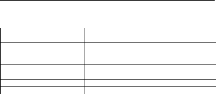
Command Set
4-
16
ADAM 4000 Series User’s Manual
ADAM-4017+
Input range and external calibrating input source for each input type
Range
bcode
(
Hex
)
Input Range Max. Signal Min Signal Displayed
Resolution
07 +/-4~20 mA +20.000 -20.000 1uA
08 +/-10 V
+10.000
-10.000
1mV
09 +/-5 V +5.0000 -5.0000 100.00uV
0a +/-1 V
+1.0000
-1.0000
100.00uV
0b +/-500 mV +500.00 -500.00 10uV
0c +/-150 mV +150.00
-150.00
10uV
0d +/-20 mA
+20.000
-20.000
1uA

Chapter 4
Chapter 4 Command Set
4-17
ADAM-4018 Command Table
Command S
y
ntax
Command Name
Command Description
Pa
g
e No.
%AANNTTCCFF Configuration Set the address, input range, baud
rate, data format, checksum status
and/or integration time for the
specified analog input module
5-4
$AA2 Configuration Status Return the configuration
parameters for the specified analog
input module
5-10
$AAF Read Version Return the firmware version code
from the specified analog input
module
5-12
$AAM Read Module Name Return the module name from the
specified analo
g
input module
5-13
#AA Read Analog Input
from all Channels Return the input value from all
channels of the specified analog
module
5-14
#AAN Read Analog Input
from Channel N Return the input value from
channels number N of the
specified analog input module
5-16
$AA5VV Enable/disable
Channels for
Multiplexing
Enables/disables multiplexing
simultaneously for seperate
channels of the specified input
module
5-17
$AA6 Read Channel
Status Ask the specified input module to
return the status of all eight
channels
5-18
$AA0 Span Calibration Calibrate the analog input module
to correct for gain errors 5-19
$AA1 Offset Calibration Calibrate the analog input module
to correct for offset errors
5-20
$AA3 CJC Status Returns the value of the CJC
sensor for a specified analog input
module
5-25
$AA9SNNNN CJC Offset
Calibration
Calibrates the CJC sensor for
offset errors
5-26

Command Set
4-
18
ADAM 4000 Series User’s Manual
ADAM-4018+ Command Table
Command Syntax Command Name Command Description Page No.
%AANNTTCCFF Configuration Set the address, input range, baud
rate, data format, checksum status
and/or integration time for the
specified analo
g
input module
5-4
$AA2 Configuration Status Return the configuration
parameters for the specified analog
input module
5-10
$AAF Read Version Return the firmware version code
from the specified analog input
module
5-12
$AAM Read Module Name Return the module name from the
specified analo
g
input module
5-13
#AA Read Analog Input
from all Channels Return the input value from all
channels of the specified analog
module
5-14
#AAN Read Analog Input
from Channel N Return the input value from
channels number N of the
specified analo
g
input module
5-16
$AA5VV Enable/disable
Channels for
Multiplexing
Enables/disables multiplexing
simultaneously for seperate
channels of the specified input
module
5-17
$AA6 Read Channel
Status Ask the specified input module to
return the status of all eight
channels
5-18
$AAB Get Operating Status
Get the channel operating status When
bit value is 0, it mean this channel is in
normal operating, when bit value is 1, it
mean this channel is opening wire
5-24
$AA3 CJC Status Returns the value of the CJC
sensor for a specified analog input
module
5-25
$AA9SNNNN
CJC Offset
Calibration
Calibrates an analog input module to
adjust for offset errors of its CJC
sensors
5-26
$AA0Ci Span Calibration
Gain error calibrate of assignment
channel, User have to input the external
standard source for calibrating process
5-27
(Continued on following page)

Chapter 4
Chapter 4 Command Set
4-19
ADAM-4018+ Command Table (Continued)
Command S
y
ntax
Command Name
Command Description
Pa
g
e No.
$AA1Ci Offset Calibration
Offset error calibrate of assignment
channel, User have to input the external
standard source for calibrating process
5-28
$AA7CiRrr Input Ran
g
e Settin
g
Input range setting individually 5-29
$AA8Ci Read Input Range Get the input range
of the assignment
channel 5-30
$AAXnnnn Set Communication
WDT
Set communication WDT cycle time from
0000 ~ 9999 (unit: 0.1 second. if value is
0000, the communication WDT function
will be disable)
5-31
$AAY Get Communication
WDT Settin
g
Read the cycle time setting of
communication WDT 5-32
ADAM-4018+
Input range and external calibrating input source for each input type
Range
bcode(Hex) Input Range Max. Signal Min Signal Displayed
Resolution
06 +/-20 mA
+20.000
-20.000
1uA
07 4~20 mA +20.000 +4.000 1uA
14 Type J
Thermocouple
15 Type K
Thermocouple
16 Type T
Thermocouple
17 Type E
Thermocouple
18 Type R
Thermocouple
19 Type S
Thermocouple
20 Type B
Thermocouple

Command Set
4-
20
ADAM 4000 Series User’s Manual
ADAM-4018M Command Table
Command Syntax Command Name Command Description Page
No.
%AANNTTCCFF Configuration Set the address, input range, baud
rate, data format, checksum status
and/or integration time for the
specified analo
g
input module
5-4
$AA2 Configuration
Status Return the configuration
parameters for the specified
analo
g
input module
5-10
$AAF Read Version Return the firmware version code
from the specified analog input
module
5-12
$AAM Read Module
Name
Return the module name from the
specified analo
g
input module
5-13
#AAN Read Analog Input
from Channel N Return the input value from
channels number N of the
specified analog input module
5-16
$AA5VV Enable/disable
Channels for
Multiplexing
Enables/disables multiplexing
simultaneously for seperate
channels of the specified input
module
5-17
$AA6 Read Channel
Status Ask the specified input module to
return the status of all eight
channels
5-18
$AA0 Span Calibration Calibrate the analog input module
to correct for gain errors 5-19
$AA1 Offset Calibration Calibrate the analog input module
to correct for offset errors
5-20
$AA3 CJC Status Returns the value of the CJC
sensor for a specified analog input
module
5-25
$AA9SNNNN CJC Offset
Calibration
Calibrates the CJC sensor for
offset errors
5-26
@AACCCSDMTTTT
Set Memory
Configuration Set the channel storage status,
standalone mode, data logger
mode, storage type and sampling
interval for the specified analog
input data lo
gg
er.
5-37
@AAD Read Memory
Configuration Return the configuration
parameters for the specified
analog input data logger.
5-39
@AASO Set Memory
Operation Mode
Start/stop the recording function of
the memor
y
module.
5-40

Chapter 4
Chapter 4 Command Set
4-21
(Continued on following page)
ADAM-4018M Command Table (Continued)
@AAT Read Memory
Operation Mode Read the recording status of the
memory module. 5-41
@AAL Event Record
Count Read the number of stored event
records in the memory module. 5-42
@AAN Standard Record
Count Read the number of stored
standard records in the memory
module.
5-43
@AARNNNN Read Record
Content
Read the contents of the specified
record.
5-44
@AAACSDHHHHTEIIII
Set Alarm Limit Set the high/low alarm settings for
the specified channel.
5-46
@AABC Read Alarm Limit Read the high/low alarm settings
for the specified channel.
5-48

Command Set
4-
22
ADAM 4000 Series User’s Manual
ADAM-4019+ Command Table
Command Syntax Command Name Command Description Page
No.
%AANNTTCCFF Configuration Sets the address, baud rate, data
format, checksum status, and/or
integration time for a specified
analo
g
input module
5-4
$AA2 Configuration
Status Returns the configuration
parameters for the specified
analo
g
input module
5-10
$AAF Read Firmware
Version Return the firmware version code
from the specified analog output
module
5-12
$AAM Read Module
Name Return the module name from the
specified analog output module 5-13
#AA Analog Data In Returns the input value from a
specified analog input module in
the currently configured data
format
5-14
#AAN Read Analog Input
from Channel N Returns the input value from a
specified channel of analog input
module in the currently configured
data format
5-16
$AA5VV Enable/Disable
Channels for
Multiplexing
Enable or disable the individual
channels in an analog module 5-17
$AA6 Read Channel
Status
Get the enable/disable status of all
channels in an analo
g
module
5-18
$AAB Get Operating Status Get the channel operating status
When
bit value is 0, it mean this channel is in
normal operating, when bit value is 1, it
mean this channel is opening wire
5-24
$AA3 CJC Status Returns the value of the CJC
sensor for a specified analog input
module
5-25
$AA9SNNNN CJC Offset
Calibration
Calibrates an analog input module to
adjust for offset errors of its CJC
sensors
5-26
(Continued on following page)

Chapter 4
Chapter 4 Command Set
4-23
ADAM-4019+ Command Table (Continued)
Command S
y
ntax
Command Name
Command Description
Pa
g
e No.
$AA0Ci Single Channel
Span Calibration Gain error calibrate of assignment
channel, User have to input the
external standard source for
calibrating process
5-27
$AA1Ci Single Channel
Offset Calibration Offset error calibrate of assignment
channel, User have to input the
external standard source for
calibrating process
5-28
$AA7CiRrr Input Range
Settin
g
Input range setting individually 5-29
$AA8Ci Read Input Range Get the input range of the assignment
channel 5-30
$AAXnnnn Set Communication
WDT Set communication WDT cycle time
from 0000 ~ 9999 (unit: 0.1 second. if
value is 0000, the communication WDT
function will be disable)
5-31
$AAY Get Communication
WDT setting
Read the cycle time setting of
communication WDT 5-32

Command Set
4-
24
ADAM 4000 Series User’s Manual
ADAM-4021 Command Table
Command Syntax Command Name Command Description Page
No.
%AANNTTCCFF Configuration Set the address, output range,
baud rate, data format, slew rate
and/or checksum status
6-3
#AA(data) Analog Data Out Directs output data to a specified
module
6-6
$AA4 Start-up output
current/voltage
confi
g
uration
Stores a default output value in a
specified module. The output
value will take effect upon startup.
6-8
$AA3(number of
counts) Trim Calibration Trims specified module a number
of units up/down 6-9
$AA0 4 mA Calibration Tells the module to store
parameters for 4 mA Calibration 6-11
$AA1 20 mA Calibration
Tells the module to store
parameters for 20 mA Calibration 6-12
$AA2 Configuration
Status
Reads configuration of specified
module
6-13
$AA6 Last Value
Readback Returns either last value sent to
specified module by #AA
command, or start-up output
current/voltage
6-14
$AA8 Current Readback Returns measured value of the
current/voltage flowing through
current loop
6-15
$AA5 Reset Status Checks if module has been reset
since the
last $AA5 command
6-16
$AAF Read Firmware
Version Return the firmware version code
from the specified analog output
module
6-17
$AAM Read Module
Name Return the module name from the
specified analog output module 6-18

Chapter 4
Chapter 4 Command Set
4-25
ADAM-4024 Command Table
Command Syntax Command Name Command Description Page
No.
%AANNTTCCFF Configuration Set the address, output range,
baud rate, data format, slew rate
and/or checksum status
6-19
#AACn(data) Analog Data Out Directs output data to a specified
module
6-20
#AASCn(data) Set Startup Data Set data As CHn StartUp Data 6-20
#AAECn(data) Set Emergency
Stop
Set data As CHn Emergency
Stop Data 6-20
#** N/A Synchrous Sample IDI 6-20
$AA0Cn 4 mA Calibration Tells the module to store
parameters for 4 mA Calibration 6-20
$AA1Cn 20 mA Calibration
Tells the module to store
parameters for 20 mA Calibration 6-20
$AA2 Configuration
Status
Read back Module status 6-20
$AA3Cn(number of
counts) Trim Calibration Trims specified module a number
of units up/down 6-20
$AA4 Start-up output
current/voltage
confi
g
uration
Stores a default output value in a
specified module. The output
value will take effect upon startup.
6-20
$AA5 Reset Status Read Back Reset Times After Last
$AA5 CMD And Clear This ounter 6-20
$AA6Cn Last Value
Readback Returns either last value sent to
specified module by #AA
command, or start-up output
current/volta
g
e
6-20
$AA7CnRxx Set Output T
y
pe Set CHn Output T
y
pe
6-20
$AA8Cn Current Readback Returns measured value of the
current/voltage flowing through
current loop
6-21
$AAF Read Firmware
Version Return the firmware version code
from the specified analog output
module
6-21
$AAM Read Module
Name Return the module name from the
specified analog output module 6-21
(Continued on following page)

Command Set
4-
26
ADAM 4000 Series User’s Manual
ADAM-4024 Command Table (Continued)
Command Syntax Command Name Command Description Page
No.
$AAACnZ EMS Flag setting Enable/Disable
(Z=1/0)
CHn EMS Flag
6-21
$AABCn Read EMS Flag
Read CHn EMS Flag 6-21
$AADCn Read startup
data Read Back CHn StartUp Data 6-21
$AAECn Read emergency
Stop
Read Back CHn Emergency
Stop Data 6-21
$AAG Reset Current
Trim Reset Current Trim Data
Variable To 0 6-21
$AAH Read Current
Trim Read Current Trim Data
Variable 6-21
$AAI Read IDI
Read IDI 6-21
$AANCn Read 4mA
Calibration
Parameter
Read Back CHn 4mA
Calibration Parameter 6-21
$AAOCn Read 20mA
Calibration
Parameter
Read Back CHn 20mA
Calibration Parameter 6-21
$AAPCn Clear 4mA
Calibration
Parameter
Clear CHn 4mA Calibration
Parameter/EEPROM 6-21
$AAQCn Clear 20mA
Calibration
Parameter
Clear CHn 20mA Calibration
Parameter/EEPROM 6-21
$AAXnnnn Watchdog Timer
Setting Set communication WDT cycle
time from 0000 ~ 9999 (unit: 0.1
second. if value is 0000, the
communication WDT function
will be disable)
6-21
$AAY Read Watchdog
Timer Setting Read the cycle time setting of
communication WDT 6-21

Chapter 4
Chapter 4 Command Set
4-27
ADAM-4050 Command Table
Command Syntax
Command Name Command Description Page
No.
%AANNTTCCFF Configuration Sets address, baud rate, and/or
checksum status, to a digital I/O
module
7-4
$AA6 Digital Data In Returns the values of the digital I/O
channels of the addressed module 7-6
#AABB(data) Digital Data Out Writes specified values to either a
single channel or all channels
simultaneousl
y
7-8
#** Synchronized
Sampling Orders all digital I/O modules to
sample their input values and store
them in a special re
g
ister
7-11
$AA4 Read
Synchronized
Data
Return the value of a specified digital
I/O module that was stored after an
#** command was issued
7-12
$AA2 Configuration
Status Returns the configuration parameters
of a specified digital I/O module 7-14
$AA5 Reset Status Indicates whether a specified digital
I/O module was reset after the last
time the $AA5 command was issued
7-16
$AAF Read Firmware
Version Return the firmware version code
from the specified di
g
ital I/O module 7-18
$AAM Read Module
Name
Return the module name from the
specified Di
g
ital I/O module
7-19

Command Set
4-
28
ADAM 4000 Series User’s Manual
ADAM-4051 Command Table
Command Syntax Command Name Command Description Page
No.
%AANNTTCCFF Configuration Sets the address, baud rate, and/or
checksum status to a digital I/O
module
7-4
#** Synchronized
Sampling Orders all digital I/O modules to
sample their input values and store
them in special re
g
isters
7-11
$AA2 Configuration
Status Returns the configuration
parameters of a specified digital I/O
module
7-14
$AA4 Read
Synchronized Data
Returns the value of a specified
digital I/O module that was stored in
the specified register after an #**
command was issued
7-12
$AA5 Reset Status Indicates whether a specified digital
I/O module was reset after the last
time that $AA5 command was
issued
7-16
$AA6 Digital Data In Returns the values of the digital I/O
channel in the addressed module 7-6
$AAF Read Firmware
Version Return the firmware version code
from the specified digital I/O module 7-18
$AAM Read Module
Name Return the module name from the
specified di
g
ital I/O module
7-19

Chapter 4
Chapter 4 Command Set
4-29
ADAM-4052 Command Table
Command Syntax Command Name Command Description Page
No.
%AANNTTCCFF Configuration Sets address, baud rate, and/or
checksum status, to a digital I/O
module
7-4
$AA6 Digital Data In Returns the values of the digital I/O
channels of the addressed module 7-6
#** Synchronized
Sampling Orders all digital I/O modules to
sample their input values and store
them in a special re
g
ister
7-11
$AA4 Read Synchronized
Data Return the value of a specified
digital I/O module that was stored
after an #** command was issued
7-12
$AA2 Configuration
Status Returns the configuration
parameters of a specified digital I/O
module
7-14
$AA5 Reset Status Indicates whether a specified digital
I/O module was reset after the last
time the $AA5 command was
issued
7-16
$AAF Read Firmware
Version
Return the firmware version code
from the specified di
g
ital I/O module 7-18
$AAM Read Module Name Return the module name from the
specified digital I/O module 7-19
$AAXnnnn Watchdog Timer
Setting Set communication WDT cycle time
from 0000 ~ 9999 (unit: 0.1 second.
if value is 0000, the communication
WDT function will be disable)
7-27
$AAY Read Watchdog
Timer Settin
g
Read the cycle time setting of
communication WDT
7-28

Command Set
4-
30
ADAM 4000 Series User’s Manual
ADAM-4053 Command Table
Command Syntax
Command Name Command Description Page
No.
%AANNTTCCFF Configuration Sets address, baud rate, and/or
checksum status, to a digital I/O
module
7-4
$AA6 Digital Data In Returns the values of the digital I/O
channels of the addressed module 7-6
#** Synchronized
Sampling Orders all digital I/O modules to
sample their input values and store
them in a special re
g
ister
7-11
$AA4 Read Synchronized
Data Return the value of a specified
digital I/O module that was stored
after an #** command was issued
7-12
$AA2 Configuration Status Returns the configuration
parameters of a specified digital I/O
module
7-14
$AA5 Reset Status Indicates whether a specified digital
I/O module was reset after the last
time the $AA5 command was
issued
7-16
$AAF Read Firmware
Version Return the firmware version code
from the specified digital I/O module 7-18
$AAM Read Module Name Return the module name from the
specified di
g
ital I/O module
7-19

Chapter 4
Chapter 4 Command Set
4-31
ADAM-4055 Command Table
Command Syntax Command Name Command Description Page
No.
%AANNTTCCFF Configuration Sets the address, baud rate, and/or
checksum status to a digital I/O
module
7-4
#AABB(data) Digital Data Out Writes specified values to either a
single channel or all channels
simultaneousl
y
7-8
#** Synchronized
Sampling Orders all digital I/O modules to
sample their input values and store
them in special registers
7-11
$AA2 Configuration
Status
Returns the configuration parameters
of a specified di
g
ital I/O module
7-14
$AA4 Read
Synchronized
Data
Returns the value of a specified digital
I/O module that was stored in the
specified register after an #**
command was issued
7-12
$AA5 Reset Status Indicates whether a specified digital
I/O module was reset after the last
time that $AA5 command was issued
7-16
$AA6 Digital Data In Returns the values of the digital I/O
channel in the addressed module
7-6
$AAF Read Firmware
Version Return the firmware version code from
the specified digital I/O module 7-18
$AAM Read Module
Name
Return the module name from the
specified di
g
ital I/O module
7-19
$AAX0TTTTDDDD
Write Safty Value Force the DO channels to safety status
when communication is time-out and
over pre-defined period.
7-21
$AAX1 Read Safty Value Read the time-out setting and
pre-defined safety status of DO
channels.
7-22
$AAX2 Read Safty Flag Requests the Safty Flag of the
addressed digital I/O module to see
whether the safety value has been
executed since Write Safety Value
command
was set.
7-23
$AAXnnnn Watchdog Timer
Setting Set communication WDT cycle time
from 0000 ~ 9999 (unit: 0.1 second. if
value is 0000, the communication
WDT function will be disable
)
7-27
$AAY Read Watchdog
Timer Settin
g
Read the cycle time setting of
communication WDT
7-28

Command Set
4-
32
ADAM 4000 Series User’s Manual
ADAM-4056S Command Table
Command Syntax Command Name Command Description Page
No.
%AANNTTCCFF Configuration Sets the address, baud rate, and/or
checksum status to a digital I/O
module
7-4
#AABB(data) Digital Data Out Writes specified values to either a
single channel or all channels
simultaneousl
y
7-8
$AA2 Configuration Status
Returns the configuration
parameters of a specified digital I/O
module
7-14
$AA5 Reset Status Indicates whether a specified digital
I/O module was reset after the last
time that $AA5 command was
issued
7-16
$AA6 Digital Data In Returns the values of the digital I/O
channel in the addressed module 7-6
$AAF Read Firmware
Version Return the firmware version code
from the specified digital I/O module 7-18
$AAM Read Module Name Return the module name from the
specified di
g
ital I/O module
7-19
$AAX0TTTTDDDD
Write Safty Value Force the DO channels to safety
status when communication is
time-out and over pre-defined
period.
7-21
$AAX1 Read Safty Value Read the time-out setting and
pre-defined safety status of DO
channels.
7-22
$AAX2 Read Safty Flag Requests the Safty Flag of the
addressed digital I/O module to see
whether the safety value has been
executed since Write Safety Value
command
was set.
7-23
$AAXnnnn Watchdog Timer
Setting Set communication WDT cycle time
from 0000 ~ 9999 (unit: 0.1 second.
if value is 0000, the communication
WDT function will be disable)
7-27
$AAY Read Watchdog
Timer Settin
g
Read the cycle time setting of
communication WDT
7-28

Chapter 4
Chapter 4 Command Set
4-33
ADAM-4056SO Command Table
Command Syntax Command Name Command Description Page
No.
%AANNTTCCFF Configuration Sets the address, baud rate, and/or
checksum status to a digital I/O
module
7-4
#AABB(data) Digital Data Out Writes specified values to either a
single channel or all channels
simultaneously
7-8
$AA2 Configuration Status
Returns the configuration
parameters of a specified digital I/O
module
7-14
$AA5 Reset Status Indicates whether a specified digital
I/O module was reset after the last
time that $AA5 command was
issued
7-16
$AA6 Digital Data In Returns the values of the digital I/O
channel in the addressed module 7-6
$AAF Read Firmware
Version Return the firmware version code
from the specified di
g
ital I/O module 7-18
$AAM Read Module Name Return the module name from the
specified digital I/O module 7-19
$AAX0TTTTDDDD
Write Safty Value Force the DO channels to safety
status when communication is
time-out and over pre-defined
period.
7-21
$AAX1 Read Safty Value Read the time-out setting and
pre-defined safety status of DO
channels.
7-22
$AAX2 Read Safty Flag Requests the Safty Flag of the
addressed digital I/O module to see
whether the safety value has been
executed since Write Safety Value
command was set.
7-23
$AAE0 Read and Clear Over
Current Status Fla
g
Read the Over Current Status Flag
and Clear
the Fla
g
simultaneousl
y
7-24
$AAXnnnn Watchdog Timer
Setting Set communication WDT cycle time
from 0000 ~ 9999 (unit: 0.1 second.
if value is 0000, the communication
WDT function will be disable
)
7-27
$AAY Read Watchdog
Timer Settin
g
Read the cycle time setting of
communication WDT
7-28

Command Set
4-
34
ADAM 4000 Series User’s Manual
ADAM-4060/4068 Command Table
Command Syntax Command Name Command Description Page
No.
%AANNTTCCFF Configuration Sets address, baud rate, and/or
checksum status, to a digital I/O
module
7-4
$AA6 Digital Data In Returns the values of the digital I/O
channels of the addressed module 7-6
#AABB(data) Digital Data Out Writes specified values to either a
single channel or all channels
simultaneously
7-8
#** Synchronized
Sampling Orders all digital I/O modules to
sample their input values and store
them in a special register
7-11
$AA4 Read Synchronized
Data Return the value of a specified digital
I/O module that was stored after an
#** command was issued
7-12
$AA2 Configuration Status
Returns the configuration parameters
of a specified digital I/O module 7-14
$AA5 Reset Status Indicates whether a specified digital
I/O module was reset after the last
time the $AA5 command was issued
7-16
$AAF Read Firmware
Version Return the firmware version code
from the specified di
g
ital I/O module 7-18
$AAM Read Module Name Return the module name from the
specified digital I/O module 7-19
$AAX0TTTTDDDD
Write Safty Value Force the DO channels to safety
status when communication is
time-out and over pre-defined period.
7-21
$AAX1 Read Safty Value Read the time-out setting and
pre-defined safety status of DO
channels.
7-22
$AAX2 Read Safty Flag Requests the Safty Flag of the
addressed digital I/O module to see
whether the safety value has been
executed since Write Safety Value
command
was set.
7-23

Chapter 4
Chapter 4 Command Set
4-35
ADAM-4069 Command Table
Command Syntax Command Name Command Description Page
No.
%AANNTTCCFF Configuration Sets address, baud rate, and/or
checksum status, to a digital I/O
module
7-4
$AA6 Digital Data In Returns the values of the digital
I/O channels of the addressed
module
7-6
#AABB(data) Digital Data Out Writes specified values to either
a single channel or all channels
simultaneousl
y
7-8
$AA2 Configuration
Status Returns the configuration
parameters of a specified digital
I/O module
7-14
$AA5 Reset Status Indicates whether a specified
digital I/O module was reset
after the last time the $AA5
command was issued
7-16
$AAF Read Firmware
Version Return the firmware version
code from the specified digital
I/O module
7-18
$AAM Read Module Name
Return the module name from
the specified digital I/O module 7-19
$AAX0TTTTDDDD Write Safty Value Force the DO channels to safety
status when communication is
time-out and over pre-defined
period.
7-21
$AAX1 Read Safty Value Read the time-out setting and
pre-defined safety status of DO
channels.
7-22
$AAP Read low power
status The command requests the
module at address AA to return
the low power status of module
7-25
$AAS Set low power
status The command requests the
module at address AA to set and
return the low power mode of
module
7-26
$AAXnnnn Watchdog Timer
Setting Set communication WDT cycle
time from 0000 ~ 9999 (unit: 0.1
second. if value is 0000, the
communication WDT function
will be disable
)
7-27
$AAY Read Watchdog
Timer Setting Read the cycle time setting of
communication WDT 7-28

Command Set
4-
36
ADAM 4000 Series User’s Manual
ADAM-4080 Command Table
Command Syntax
Command Name Command Description Page
No.
%AANNTTCCFF Configuration Sets the address, input mode,
baud rate, checksum status and/or
frequency gate time for a specified
counter/ frequency module
7-28
$AA2 Configuration Status Returns configuration parameters
from the specified
counter/frequenc
y
module
7-30
$AAF Read Firmware
Version Return firmware version code from
the specified counter/frequency
module
7-31
$AAM Read Module Name Return the module name from the
specified counter/frequency
module
7-32
$AABS Set Input Signal
Mode Sets the input signal mode of the
specified counter/frequency
module to either non-isolated or
photo-isolated input si
g
nals
7-33
$AAB Read Input Signal
Mode Read the input signal mode of the
specified counter/frequency
module.
7-34
#AAN Read Counter or
Frequency Value Returns the value of counter 0 or
counter 1 from a specified counter/
frequenc
y
module in hex format
7-35
(Continued on following page)

Chapter 4
Chapter 4 Command Set
4-37
ADAM-4080 Command Table (Continued)
Command Syntax
Command Name Command Description Page
No.
$AAAG Set Gate Mode Requests the specified
counter/frequency module to set its
gate mode to either high, low or
disabled
7-40
$AAA Read Gate Mode Requests the specified
counter/frequency module to return
the status of its gate mode
7-41
$AA3N(data) Set Maximum
Counter Value Sets the maximum value of counter
0 or counter 1 for the specified
counter/frequenc
y
module
7-42
$AA3N Read Maximum
Counter Value Reads the maximum value of
counter 0 or counter 1 of the
specified counter/frequenc
y
module
7-43
$AA5NS Start/Stop Counter The command orders the specified
counter/frequency module to start
or stop counting
7-44
$AA5N Read Counter
Start/Stop Status The addressed counter frequency
module returns its status indicating
whether counting is enabled or
disabled
7-45
$AA6N Clear Counter The command clears the counter 0
or counter 1 of the specified counter
module
7-46
$AA7N Read Overflow Flag The addressed module returns the
status of the overflow flag of
counter 0 or counter 1
7-47
(Continued on following page)

Command Set
4-
38
ADAM 4000 Series User’s Manual
ADAM-4080 Command Table (Continued)
Command Syntax
Command Name Command Description Page
No.
$AA4S Enable/Disable
Digital Filter Enables or disables the digital
filter of the addressed
counter/frequency module
7-49
$AA4 Read Filter Status The addressed counter frequency
module returns the status of its
di
g
ital filter
7-50
$AA0H(data) Set Minimum Input
Signal Width at High
Level
Sets the minimum input signal
width at high level for a specified
counter/frequenc
y
module
7-51
$AA0H Read Minimum Input
Signal Width at High
Level
Reads the minimum input signal
width setting at high level for a
specified counter/frequency
module
7-52
$AA0L(data) Set Minimum Input
Signal Width at Low
Level
Sets the minimum input signal
width at low level for a specified
counter/frequenc
y
module
7-53
$AA0L Read Minimum Input
Signal Width at Low
Level
Reads minimum input signal
width setting at low level for a
specified counter/frequency
module
7-54
$AA1H(data) Set Non-isolated
High Trigger Level Sets the high trigger level of
non-isolated input signals for a
specified counter/frequency
module
7-55
$AA1H Read Non-isolated
High Trigger Level Requests the addressed counter
frequency module to return the
high trigger level for non-
7-56
$AA1L(data) Set Non-isolated Low
Trigger Level isolated input signals 7-57
$AA1L Read Non-isolated
Low Trigger Level Sets the low trigger level of
non-isolated input signals for a
specified counter/frequency
module
7-58
(Continued on following page)

Chapter 4
Chapter 4 Command Set
4-39
ADAM-4080 Command Table (Continued)
Command Syntax
Command Name Command Description Page
No.
@AAPN(data) Set Initial Count
Value of Counter N Sets the initial count value of the
module for counter 0 or counter 1 7-61
@AAGN Read Initial Count
Value of Counter N Reads the initial count value of
counter 0 or counter 1 7-62
@AAEAN Enable Alarm of
Counter N
Enable alarm for the specified
counter 0 or counter 1
7-63
@AADAN Disable Alarm of
Counter N Disable alarm for the specified
counter 0 or counter 1 7-64
@AAPA(data) Set Alarm Limit Value
of Counter 0
Download the alarm limit value for
counter 0 of the specified module 7-65
@AASA(data) Set Alarm Limit Value
of Counter 1
Download the alarm limit value for
counter 1 of the specified module 7-65
@AARP Read Alarm Limit
Value of Counter 0 Ask the module to return the alarm
limit value of counter 0 7-66
@AARA Read Alarm Limit
Value of Counter 1 Ask the module to return the alarm
limit value of counter 1 7-66
@AADO (data) Set Digital Output
Values Set the values of the module's two
digital outputs (ON or OFF) 7-67
@AADI Read Digital Output
and Alarm Status Ask the module to return the
status state of its two digital
outputs and the status of its alarm.
7-68

Command Set
4-
40
ADAM 4000 Series User’s Manual
ADAM-4080D Command Table
Command Syntax
Command Name Command Description Page
No.
%AANNTTCCFF Configuration Sets the address, input mode,
baud rate, checksum status and/or
frequency gate time for a specified
counter/ frequency module
7-28
$AA2 Configuration Status Returns configuration parameters
from the specified
counter/frequenc
y
module
7-30
$AAF Read Firmware
Version Return firmware version code from
the specified counter/frequency
module
7-31
$AAM Read Module Name Return the module name from the
specified counter/frequency
module
7-32
$AABS Set Input Signal
Mode Sets the input signal mode of the
specified counter/frequency
module to either non-isolated or
photo-isolated input si
g
nals
7-33
$AAB Read Input Signal
Mode Read the input signal mode of the
specified counter/frequency
module.
7-34
#AAN Read Counter or
Frequency Value Returns the value of counter 0 or
counter 1 from a specified counter/
frequenc
y
module in hex format
7-35
$AA8V Select LED Data
Origin Select whether LED will display
data from the counter/frequency
module directly or from the host
computer
7-36
$AA8 Read LED Data
Origin Returns the status of the LED Data
origin. Origin is either direct from
module or from host computer
7-37
$AA9(data) Send Data to LED The host computer sends data to
the addressed module to display
on its LED. This command is valid
only after selectting to display host
computer data
(
$AA8V
)
7-38
(Continued on following page)

Chapter 4
Chapter 4 Command Set
4-41
ADAM-4080D Command Table (Continued)
Command Syntax
Command Name Command Description Page
No.
$AAAG Set Gate Mode Requests the specified counter/
frequency module to set its gate
mode to either hi
g
h, low or disabled
7-40
$AAA Read Gate Mode Requests the specified counter/
frequency module to return the
status of its gate mode
7-41
$AA3N(data) Set Maximum
Counter Value Sets the maximum value of counter
0 or counter 1 for the specified
counter/frequenc
y
module
7-42
$AA3N Read Maximum
Counter Value Reads the maximum value of
counter 0 or counter 1 of the
specified counte/ frequency module
7-43
$AA5NS Start/Stop Counter The command orders the specified
counter/frequency module to start
or stop counting
7-44
$AA5N Read Counter
Start/Stop Status The addressed counter frequency
module returns its status indicating
whether counting is enabled or
disabled
7-45
$AA6N Clear Counter The command clears the counter 0
or counter 1 of the specified
counter module
7-46
$AA7N Read Overflow Flag The addressed module returns the
status of the overflow flag of
counter 0 or counter 1
7-47
(Continued on following page)

Command Set
4-
42
ADAM 4000 Series User’s Manual
ADAM-4080D Command Table (Continued)
Command Syntax
Command Name Command Description Page
No.
$AA4S Enable/Disable
Digital Filter Enables or disables the digital
filter of the addressed
counter/frequency module
7-49
$AA4 Read Filter Status The addressed counter frequency
module returns the status of its
di
g
ital filter
7-50
$AA0H(data) Set Minimum Input
Signal Width at High
Level
Sets the minimum input signal
width at high level for a specified
counter/frequenc
y
module
7-51
$AA0H Read Minimum Input
Signal Width at High
Level
Reads the minimum input signal
width setting at high level for a
specified counter/frequency
module
7-52
$AA0L(data) Set Minimum Input
Signal Width at Low
Level
Sets the minimum input signal
width at low level for a specified
counter/frequenc
y
module
7-53
$AA0L Read Minimum Input
Signal Width at Low
Level
Reads minimum input signal
width setting at low level for a
specified counter/frequency
module
7-54
$AA1H(data) Set Non-isolated
High Trigger Level Sets the high trigger level of
non-isolated input signals for a
specified counter/frequency
module
7-55
$AA1H Read Non-isolated
High Trigger Level Requests the addressed counter
frequency module to return the
high trigger level for non-isolated
input si
g
nals
7-56
$AA1L(data) Set Non-isolated Low
Trigger Level Sets the low trigger level of
non-isolated input signals for a
specified counter/frequency
module
7-57
$AA1L Read Non-isolated
Low Trigger Level Sets the low trigger level of
non-isolated input signals for a
specified counter/frequency
module
7-58
(Continued on following page)

Chapter 4
Chapter 4 Command Set
4-43
ADAM-4080D Command Table (Continued)
Command Syntax
Command Name Command Description Page
No.
@AAEAT Enable Alarm Enable the alarm in either
momentary or latching mode 7-69
@AADA Disable Alarm Disable all alarm functions 7-70
@
AACA Clear Latch Alarm
The latch alarm is reset
7-71
@AAPA(data) Set Low-Alarm
Count Value of
Counter 0
Downloads the low-alarm count
value for counter 0 of the specified
counter/frequency module
7-72
@AASA(data) Set High-Alarm
Count Value of
Counter 0
Downloads the high-alarm count
value for counter 0 of the specified
counter/frequenc
y
module
7-73
@AARP Read Low-Alarm
Count Value of
Counter 0
Ask the addressed module to
return its low-alarm count value for
counter 0
7-74
@AARA Read High-Alarm
Count Value of
Counter 0
Ask the addressed module to
return its high-alarm count value
for counter 0
7-75
@AADO(data) Set Digital Output
Values
Set the values of the module's two
di
g
ital outputs
(
ON or OFF
)
7-67
@AADI Read Digital Output
and Alarm Status Ask the module to return the status
state of its two digital outputs and
the status of its alarm.
7-68
Analog Input Module Command Set 5

5-2
ADAM 4000 Series User’s Manual
5.1 Analog Input Common Command Set
Command
S
y
ntax
Description I/O Module
%AANNTTCCF
F
Sets the address, input range,
baud rate, data format,
checksum status, and/or
integration time for a specified
analo
g
input module
4011, 4011D, 4012, 4013, 4015,
4015T, 4016, 4017, 4017+, 4018,
4018+, 4018M, 4019+
$AA2 Returns the configuration
parameters for the specified
analo
g
input module
4011, 4011D, 4012, 4013, 4015,
4015T, 4016, 4017, 4017+, 4018,
4018+,
4018M, 4019+
$AAF Returns the firmware version
code from the specified analog
input module
4011, 4011D, 4012, 4013, 4015,
4015T, 4016, 4017, 4017+, 4018,
4018+,
4018M,
4019+
$AAM Returns the module name from
the specified analog input
module
4011, 4011D, 4012, 4013, 4015,
4015T, 4016, 4017, 4017+, 4018,
4018+, 4018M, 4019+
#AA Returns the input value from a
specified analog input moudule
in the currently configured data
format
4011, 4011D, 4012, 4013, 4015,
4015T, 4016, 4017, 4017+, 4018,
4018+, 4019+
#AAN Returns the input value from
channel number n of the
specified analog input module
4015, 4015T, 4017, 4017+, 4018,
4018+, 4018M, 4019+
#AA5VV Enables/disables multiplexing
simultaneously for separate
channels of the specified input
module
4015, 4015T, 4017, 4017+, 4018,
4018+, 4018M, 4019+
$AA6 Ask the specified input module
to return the status of all eight
channels
4015, 4015T, 4017, 4017+, 4018+,
4018, 4018M, 4019+
$AA0 Calibrate the analog input
module to correct for gain errors
4011, 4011D, 4012, 4013, 4016,
4017, 4018, 4018M
$AA1 Calibrate the analog input
module to correct for offset
errors.
4011, 4011D, 4012, 4013, 4016,
4017, 4018, 4018M
#** Orders all analog input modules
to sample their input values and
store them in special re
g
isters
4011, 4011D, 4012, 4013, 4015,
4015T, 4016
(Continued on following page)

Chapter 5
5-3
ADAM 4000 Series User’s Manual
Command
S
y
ntax
Command Description I/O Module
$AA4 Returns the value that was
stored in the specified module's
register after the #** command
4011, 4011D, 4012, 4013, 4015,
4015T, 4016
$AAB Ask the module to respond
whether the wiring is open or
closed
4011D, 4015, 4015T, 4018+,
4019+
$AA3 Returns the value of the CJC
sensor for a specified analog
input module
4011, 4011D, 4018, 4018+,
4018M, 4019+
$AA9 Calibrates the CJC sensor for
offset errors
4011, 4011D, 4018, 4018+, 4018M
4019+
$AA0Ci Calibrates a specified channel
to correct for
g
ain errors
4015, 4015T, 4017+, 4018+, 4019+
$AA1Ci Calibrates a specified channel
to correct for offset errors
4015, 4015T, 4017+, 4018+, 4019+
$AA7CiRrr Configure the input type and
range of the specified channel
in an analo
g
input module
4015, 4015T, 4017+, 4018+, 4019+
$AA8Ci Get the input type and range of
the specified channel in an
analo
g
input module
4015, 4015T, 4017+, 4018+, 4019+
$AAXnnnn Communication Watchdog Timer
Setting
4015, 4015T, 4017+, 4018+,4019+
$AAY Read Communication Watchdog
Timer Setting
4015, 4015T, 4017+, 4018+, 4019+
$AAS0 Internal self-calibration for offset
and
g
ain errors
4015, 4015T
$AAS1 Reload factory default
calibrating parameter to
overwrite current calibrating
parameter
4015, 4015T

5-4
ADAM 4000 Series User’s Manual
4011, 4011D, 4012, 4013, 4015, 4015T, 4016,
4017, 4017+, 4018, 4018+, 4018M, 4019+
%AANNTTCCFF
Name Configuration command
Description Sets address, input range, baud rate, data format, checksum
status, and/or integration time for an analog input module.
Syntax %AANNTTCCFF(cr)
% is a delimiter character.
AA (range 00-FF) represents the 2-character hexadecimal
address of the analog input module you want to configure.
NN represents the new hexadecimal address of the analog
input module. Range is from 00h to FFh.
TT represents the type (input range) code. (Note: 4015 and
4019 must be 00)
(Refer to Table 5-1 on Page 5-6)
CC represents the baud rate code.
(Refer to Table 5-2 on Page 5-8)
FF is a hexadecimal number that equals the 8-bit parameter
representing the data format, checksum status and
integration time. The layout of the 8-bit parameter is shown
in Figure 5-1. Bits 2 through 5 are not used and are set to 0.
(cr) is the terminating character, carriage return (0Dh)
76543210
Checksum status
0: Disabled
1: Enabled
Integration time
0: 50 ms (Operation under 60 Hz power)
1: 60 ms (Operation under 50 Hz power)
not used
00: Engineering units
01: % of FSR
10: two's complement of hexadecimal
11: Ohms (for 4013 and 4015)
Data Format
Figure 5-1 Data format for FF (8-bit parameter)

Chapter 5
5-5
ADAM 4000 Series User’s Manual
4011, 4011D, 4012, 4013, 4015, 4015T, 4016,
4017, 4017+, 4018, 4018+, 4018M, 4019+
%AANNTTCCFF
Response !AA(cr) if the command is valid.
?AA(cr) if an invalid parameter was entered or if the INIT*
terminal was not grounded when attempting to change baud
rate or checksum settings.
There is no response if the module detects a syntax error or
communication error or if the specified address does not
exist.
! delimiter character indicates a valid command was
received.
? delimiter character indicates the command was invalid
AA (range 00-FF) represents the 2-character hexadecimal
address of an analog input module.
(cr) is the terminating character, carriage return (0Dh)
Example command: %2324050600(cr)
response: !24(cr)
The ADAM-4011 module with address 23h is configured to
a new address of 24h, an input range ±2.5 V, baud rate
9600, integration time 50 ms (60 Hz), engineering units
data format and no checksum checking or generation.
The response indicates that the command was received.
Wait 7 seconds to let the new configuration settings take
effect before issuing a new command to the module.
NOTICE: Only ADAM-4011, ADAM-4011D, ADAM-4012, ADAM-4013,
ADAM-4016 and ADAM-4018+ support “% of FSR” and “two’s
complement of hexadecimal” Data Format.
NOTICE: An analog input module requires a maximum of 7 seconds to
perform auto calibration and ranging after it is reconfigured.
During this time span, the module cannot be addressed to
perform any other actions.
NOTICE: All configuration parameters can be changed dynamically,
except checksum and baud rate parameters. They can only be
altered when the INIT* terminal is grounded. (Refer to Baud
rate and Checksum configuration in Chapter 2, for the correct
procedure)

5-6
ADAM 4000 Series User’s Manual
4011, 4011D, 4012, 4013, 4015, 4015T, 4016,
4017, 4017+, 4018, 4018+, 4018M, 4019+
Table 5-1 Input Range Codes (Type Codes)
Input Range Code (Hex) Input Range for 4011, 4011D, 4018, 4018+
(Thermocouple and ± 20 mA only), 4018M
00 ± 15 mV
01 ± 50 mV
02 ± 100 mV
03 ± 500 mV
04 ± 1 V
05 ± 2.5 V
06 ± 20 mA
0E Type J Thermocouple 0 ~ 760 ℃
0F Type K Thermocouple 0 ~ 1370 ℃
10 Type T Thermocouple -100 ~ 400 ℃
11 Type E Thermocouple 0 ~ 1000 ℃
12 Type R Thermocouple 500 ~ 1750 ℃
13 Type S Thermocouple 500 ~ 1750 ℃
14 Type B Thermocouple 500 ~ 1800 ℃
Input Range Code(Hex) Input Range for 4012,4017,4017+
08 ± 10 V
09 ± 5 V
0A ± 1 V
0B ± 500 mV
0C ± 150 mV
0D ± 20 mA
Notice: The input range requires the usage of a 125 Ω current conversion resistor
Input Rage Code (Hex) Input Range for 4016
00 ±15 mV
01 ±50 mV
02 ±100 mV
03 ±500 mV
06 ±20 mA

Chapter 5
5-7
ADAM 4000 Series User’s Manual
4011, 4011D, 4012, 4013, 4015, 4015T, 4016,
4017, 4017+, 4018, 4018+, 4018M, 4019+
Input Range Code (Hex) Input Range for 4013
20 Platinum, -100 ~ 100 ℃, a=0.00385
21 Platinum, 0 ~ 100 ℃, a=0.00385
22 Platinum, 0 ~ 200 ℃, a=0.00385
23 Platinum, 0 ~ 600 ℃, a=0.00385
24 Platinum, -100 ~ 100 ℃, a=0.003916
25 Platinum, 0 ~ 100 ℃, a=0.003916
26 Platinum, 0 ~ 200 ℃, a=0.003916
27 Platinum, 0 ~ 600 ℃, a=0.003916
28 Nickel, -80 ~ 100 ℃
29 Nickel, 0 ~ 100 ℃
ADAM-4015/4015T command codes against Input ranges table
Command Code (Hex) Input Type Input Range
20 Platinum 100 (IEC) -50 ~ 150 ℃
21 Platinum 100 (IEC) 0 ~ 100 ℃
22 Platinum 100 (IEC) 0 ~ 200 ℃
23 Platinum 100 (IEC) 0 ~ 400 ℃
24 Platinum 100 (IEC) -200 ~ 200 ℃
25 Platinum 100 (JIS) -50 ~ 150 ℃
26 Platinum 100 (JIS) 0 ~ 100 ℃
27 Platinum 100 (JIS) 0 ~ 200 ℃
28 Platinum 100 (JIS) 0 ~ 400 ℃
29 Platinum 100 (JIS) -200 ~ 200 ℃
2A Platinum 1000
-40 ~ 160 ℃
2B BALCO 500
-30 ~ 120 ℃
2C Ni 604 -80 ~ 100 ℃
2D Ni 604 0 ~ 100 ℃
IEC RTD 100O, α = 0.00385
JIS RTD 100O, α = 0.00391

5-8
ADAM 4000 Series User’s Manual
4011, 4011D, 4012, 4013, 4015, 4015T, 4016,
4017, 4017+, 4018, 4018+, 4018M, 4019+
Input Range Code (Hex) Input Range for 4019+
02 ± 100 mV
03 ± 500 mV
04 ± 1 V
05 ± 2.5 V
07 +4~20mA
08 ± 10 V
09 ± 5 V
0D ± 20 mA
0E Type J Thermocouple 0 ~ 760 ℃
0F Type K Thermocouple 0 ~1370 ℃
10 Type T Thermocouple -100 ~ 400 ℃
11 Type E Thermocouple 0 ~ 1000 ℃
12 Type R Thermocouple 500 ~ 1750 ℃
13 Type S Thermocouple 500 ~ 1750 ℃
14 Type B Thermocouple 500 ~ 1800 ℃
Table 5-2 Baud Rate Codes
Baud Rate Code (Hex) Baud Rate
03 1200 bps
04 2400 bps
05 4800 bps
06 9600 bps
07 19.2 kbps
08 38.4 kbps

Chapter 5
5-9
ADAM 4000 Series User’s Manual
4011, 4011D, 4012, 4013, 4015, 4015T, 4016,
4017, 4017+, 4018, 4018+, 4018M, 4019+
$AA2
Name Configuration Status command
Description The command requests the return of the configuration data
from the analog input module at address AA.
Syntax $AA2(cr)
$ is a delimiter character.
AA (range 00-FF) represents the 2-character hexadecimal
address of the analog input module that you want to
interrogate.
2 is the Configuration Status command.
(cr) is the terminating character, carriage return (0Dh).
Response !AATTCCFF(cr) if the command is valid.
?AA(cr) if an invalid operation was entered.
There is no response if the module detects a syntax error or
communication error or if the specified address does not
exist.
! delimiter character indicates a valid command was
received.
? delimiter character indicates the command was invalid.
AA (range 00-FF) represents the 2-character hexadecimal
address of an analog input module.
TT represents the type code. Type code determines the
input range.
CC represents the baud rate code.
FF is a hexadecimal number that equals the 8-bit parameter
that represents the data format, checksum status and
integration time. The layout of the 8-bit parameter is shown
in figure 4-1. Bits 2 to 5 are not used, and are set to 0.
(cr) is the terminating character, carriage return (0Dh).
(Please refer to %AANNTTCCFF configuration command
to see TT, CC and FF parameter definition)

5-10
ADAM 4000 Series User’s Manual
4011, 4011D, 4012, 4013, 4015, 4015T, 4016,
4017, 4017+, 4018, 4018+, 4018M, 4019+
$AA2
Example command: $452(cr)
response: !45050600(cr)
The command asks the analog input module at address 45h
to send its configuration data.
The analog input module at address 45h responds with an
input range of 2.5 volts, a baud rate of 9600 bps, an
integration time of 50 ms (60 Hz), engineering units are the
currently configured data format, and no checksum
function or checksum generation.

Chapter 5
5-11
ADAM 4000 Series User’s Manual
4011, 4011D, 4012, 4013, 4015, 4015T, 4016,
4017, 4017+, 4018, 4018+, 4018M, 4019+
$AAF
Name Read Firmware Version command
Description The command requests the analog input module at address
AA to return the version code of its firmware.
Syntax $AAF (cr)
$ is a delimiter character.
AA (range 00-FF) represents the 2-character hexadecimal
address of the analog input module that you want to
interrogate.
F is the Read Firmware Version command.
(cr) is the terminating character, carriage return (ODh).
Response !AA(Version)(cr) if the command is valid.
There is no response if the module detects a syntax error or
communication error, or if the specified address does not
exist.
! is a delimiter character indicating a valid command was
received.
AA (range 00-FF) represents the 2-character hexadecimal
address of an analog input module.
(Version) is the version code of the module’s firmware at
address AA.
(cr) is the terminating character, carriage return (ODh).

5-12
ADAM 4000 Series User’s Manual
4011, 4011D, 4012, 4013, 4015, 4015T, 4016,
4017, 4017+, 4018, 4018+, 4018M, 4019+
$AAM
Name Read Module Name command
Description The command requests the analog input module at address
AA to return its name.
Syntax $AAM (cr)
$ is a delimiter character.
AA (range 00-FF) represents the 2-character hexadecimal
address of the analog input module that you want to
interrogate.
M is the Read Module Name command.
(cr) is the terminating character, carriage return (ODh).
Response !AA(Module Name)(cr) if the command is valid.
There is no response if the module detects a syntax error or
communication error, or if the specified address does not
exist.
! is a delimiter character indicating a valid command was
received.
AA (range 00-FF) represents the 2-character hexadecimal
address of an analog input module.
(Module Name) is the name of the module at address AA.
(cr) is the terminating character, carriage return (ODh).

Chapter 5
5-13
ADAM 4000 Series User’s Manual
4011, 4011D, 4012, 4013, 4015, 4015T, 4016,
4017, 4017+, 4018, 4018+, 4019+
#AA
Name Analog Data In command
Description The command will return the input value from a specified
(AA) module in the currently configured data format.
Syntax #AA(cr)
# is a delimiter character.
AA (range 00-FF) represents the 2-character hexadecimal
address of an analog input module.
(cr) is the terminating character, carriage return (0Dh).
Response >(data)(cr)
There is no response if the module detects a syntax error or
communication error or if the specified address does not
exist.
> is a delimiter character.
(data) is the input value in the configured data format of
the interrogated module.
(For data formats, see Appendix B).
(cr) is the terminating character, carriage return (0Dh).
Example command: #21(cr)
response: >+7.2111+7.2567+7.3125+7.1000
+7.4712+7.2555+7.1234+7.5678 (cr)
The command interrogates the analog input module at
address 21h for its input values of all channels.
The analog input module responds with channels from 0 to
7 with +7.2111 volts, +7.2567 volts, +7.3125 volts,
+7.1000 volts, +7.4712 volts, +7.2555 volts, +7.1234 volts
and +7.5678 volts.

5-14
ADAM 4000 Series User’s Manual
4011, 4011D, 4012, 4013, 4015, 4015T, 4016,
4017, 4017+, 4018, 4018+, 4019+
#AA
Example command: #DE(cr)
response: >FF5D(cr)
The analog input module at address DEh has an input value
of FF5D. (The configured data format of the analog input
module is two’s complement)
Two’s complement % of Span Engineering units
under 0000 -0000 -0000
over FFFF +9999 +9999
NOTICE: When modules measure Thermocouple or RTD input values that
are outside their configured range they will send data that
implies input out of bounds. The next table shows the values
that the modules will return, depending on the configured data
format and if the input value falls under or exceeds the
configured range.
Only when modules are configured for Thermocouple or RTD,
“input out of bounds” warning will occur. When analog input
modules measure voltage or current that falls outside the
configured range, they will return the actual measured input!
In the next example the target module is configured for an
input range of T/C type J (Input range: 0 ~ 760 ℃) and for
a data format in engineering units. The module measures an
input value of 820 ℃.
Example command: #D1(cr)
response: >+9999(cr)
By returning a high value, +9999, the module at address
D1h indicates that the measured input value exceeds the
configured range.

Chapter 5
5-15
ADAM 4000 Series User’s Manual
4015, 4015T, 4017, 4017+, 4018,
4018+, 4018M, 4019+
#AAN
Name Read Analog Input from Channel N command
Description The command will return the input value from one of the
eight channels of a specified (AA) module in the currently
configured data format.
Syntax #AAN(cr)
# is a delimiter character.
AA (range 00-FF) represents the 2-character hexadecimal
address of the analog input module.
N identifies the channel you want to read. The value can
range from 0 to 7 for 4017, 4018, 4018M, 4019. (The range
of 4015 is from 0 to 5)
(cr) is the terminating character, carriage return (0Dh).
Response >(data)(cr)
There is no response if the module detects a syntax error or
communication error or if the specified address does not
exist.
> is a delimiter character.
(data) is the input value of the channel number N. Data
consists of a + or - sign followed by five decimal digits
with a fixed decimal point.
(cr) is the terminating character, carriage return (0Dh).
Example command: #120(cr)
response: >+1.4567(cr)
The command requests the analog input module at address
12h to return the input value of channel 0.
The analog input module responds that the input value of
channel 0 is equal to +1.4567 volts.

5-16
ADAM 4000 Series User’s Manual
4015, 4015T, 4017, 4017+, 4018,
4018+, 4018M, 4019+
$AA5VV
Name Enable/disable Channels for Multiplexing command
Description Enables/disables multiplexing simultaneously for separate
channels of a specified input module.
Syntax $AA5VV(cr)
$ is a delimiter character.
AA (range 00-FF) represents the 2-character hexadecimal
address of analog input module.
5 is the Enable/disable Channels command.
VV are two hexadecimal values. The values are interpreted
by the module as two binary words (4-bit). The first word
represents the status of channel 4~7, and the second word
represents the status of channel 0~3. Value 0 means the
channel is disabled, value 1 means the channel is enabled.
(cr) is the terminating character, carriage return (0Dh).
Response !AA(cr) if the command is valid.
?AA(cr) if an invalid operation was entered.
There is no response if the module detects a syntax error or
communication error or if the specified address does not
exist.
! delimiter character indicates a valid command was
received.
? delimiter character indicates the command was invalid.
AA (range 00-FF) represents the 2-character hexadecimal
address of an analog input module.
(cr) is the terminating character, carriage return (0Dh).
Example command: $00581(cr)
response: !00(cr)
Hexadecimal 8 equals binary 1000, which enables channel
7 and disables channels 4, 5, and 6.
Hexadecimal 1 equals binary 0001, which enables channel
0 and disables channel 1, 2, and 3.

Chapter 5
5-17
ADAM 4000 Series User’s Manual
4015, 4015T, 4017, 4017+, 4018,
4018+, 4018M, 4019+
$AA6
Name Read Channel Status command
Description Asks a specified input module to return the status of all
channels.
Syntax $AA6(cr)
AA (range 00-FF) represents the 2-character hexadecimal
address of analog input module of which the channel status
you want to send. The channel status defines whether a
channel is enabled or disabled.
6 is the Read Channel Status command.
(cr) is the terminating character, carriage return (0Dh).
Response !AAVV(cr) if the command is valid.
?AA(cr) if an invalid operation was entered.
There is no response if the module detects a syntax error or
communication error or if the specified address does not
exist.
! delimiter character indicates a valid command was
received.
? delimiter character indicates the command was invalid.
AA (range 00-FF) represents the 2-character hexadecimal
address of an analog input module.
VV are two hexadecimal values. The values are interpreted
by the module as two binary words (4-bit). The first word
represents the status of channel 4-7, and the second word
represents the status of channel 0-3. Value 0 means the
channel is disabled, value 1 means the channel is enabled.
(cr) is the terminating character, carriage return (0Dh).
Example command: $026(cr)
response: !02FF(cr)
The command asks the analog input module at address 02
to send the status of it input channels. The analog input
module at address 02 responds that all its multiplex
channels are enabled (FF equals 1111 and 1111).

5-18
ADAM 4000 Series User’s Manual
4011, 4011D, 4012, 4013,
4016, 4017, 4018, 4018M
$AA0
Name Span Calibration command
Description Calibrates an analog input module to correct for gain errors.
Syntax $AA0(cr)
$ is a delimiter character.
AA (range 00-FF) represents the 2-character hexadecimal
address of the analog input module which is to be
calibrated.
0 is the Span Calibration command.
(cr) is the terminating character, carriage return (0Dh).
Response !AA(cr) if the command was valid.
?AA(cr) if an invalid operation was entered.
There is no response if the module detects a syntax error or
communication error or if the specified address does not
exist.
! delimiter character indicates a valid command was
received.
? delimiter character indicates the command was invalid.
AA (range 00-FF) represents the 2-character hexadecimal
address of the analog input module.
(cr) represents terminating character, carriage return (0Dh).
In order to successfully calibrate an analog input module’s
input range, a proper calibration input signal should be
connected to the analog input module before and during the
calibration. (See also Chapter 8, Calibration)
NOTICE: An analog input module requires a maximum of 7 seconds to
perform auto calibration and ranging after it received a Span
Calibration command. During this interval, the module can not
be addressed to perform any other actions.

Chapter 5
5-19
ADAM 4000 Series User’s Manual
4011, 4011D, 4012, 4013,
4016, 4017, 4018, 4018M
$AA1
Name Offset Calibration command
Description Calibrates an analog input module to correct for offset
errors.
Syntax $AA1(cr)
$ is a delimiter character.
AA (range 00-FF) represents the 2-character hexadecimal
address of the analog input module you want to calibrate.
1 is the Offset Calibration command.
(cr) is the terminating character, carriage return (0Dh).
Response !AA(cr) if the command is valid.
?AA(cr) if an invalid operation was entered.
There is no response if the module detects a syntax error or
communication error or if the specified address does not
exist.
! delimiter character indicates a valid command was
received.
? delimiter character indicates the command was invalid.
AA (range 00-FF) represents the 2-character hexadecimal
address of the analog input module.
(cr) represents terminating character, carriage return (0Dh).
In order to successfully calibrate an analog input module’s
input range, a proper calibration input signal should be
connected to the analog input module before and during the
calibration. (See also Chapter 8, Calibration)
NOTICE: An analog input module requires a maximum of 7 seconds to
perform auto calibration and ranging after it received an Offset
Calibration command. During this interval, the module can not
be addressed to perform any other actions.

5-20
ADAM 4000 Series User’s Manual
4011, 4011D, 4012, 4013,
4015, 4015T, 4016
#**
Name Synchronized Sampling command
Description Orders all analog input modules to sample their input
values and store the values in special registers.
Syntax #**
# is a delimiter character.
** is the Synchronized Sampling command.
The terminating character, in the form of a carriage return
(0Dh), is not required.
Response The analog input modules will send no response after
executing the synchronized sampling command. In order to
retrieve the data, a separate Read Synchronized Data
command has to be issued for every analog input module.
The pound sign (#) followed by two asterisks (**) does not
represent an optional value, but is the actual command
string.

Chapter 5
5-21
ADAM 4000 Series User’s Manual
4011, 4011D, 4012, 4013,
4015, 4015T, 4016
$AA4
Name Read Synchronized Data command
Description Returns the input value that was stored in the addressed
module’s register, after a Synchronized Sampling command
#** was issued.
Syntax $AA4(cr)
$ is a delimiter character.
AA (range 00-FF) represents the 2-character hexadecimal
address of the analog input module from which data is to be
sent.
4 is the Read Synchronized Data command.
(cr) is the terminating character, carriage return (0Dh).
Response !AA(status)(data)(cr) if the command was valid.
?AA(cr) if an invalid operation was entered.
There is no response if the module detects a syntax error or
communication error or if the specified address does not
exist.
! delimiter character indicates a valid command was
received.
AA (range 00-FF) represents the 2-character hexadecimal
address of the analog input module that is responding.
(status) will tell you if the data (data) from the last
Synchronized Sampling command (#**) has already been
sent. If status = 1, then the data has been sent for the first
time since a Synchronized Sampling command was issued.
If status = 0, then the data has been sent at least once
before.
(data) a value stored in a special register of the interrogated
module in the configured data format. It has been sampled
by the module after a Synchronized Sampling command.
(For possible data formats, see Appendix B, Data Formats
and I/O Ranges)
(cr) represents terminating character, carriage return (0Dh).

5-22
ADAM 4000 Series User’s Manual
4011, 4011D, 4012, 4013,
4015, 4015T, 4016
$AA4
Example command: $074(cr)
response: >071+5.8222(cr)
The command asks the analog input module at address 07h
to send its analog input data.
The analog input module responds with status = 1, which
means that this is the first time that the data has been sent
and that the data = +5.8222 Volts.
(Configured data format of the analog input module in this
case is engineering units.)
command: $074(cr)
response: >070+5.8222(cr)
The command asks the analog input module at address 07h
to send its analog input data.
The analog input module responds with status = 0, which
means that it has sent the same data at least once before,
and data = +5.8222 Volts. This could indicate that a
previous Synchronized Sampling command was not
received!
(Configured data format of the analog input module in this
case is engineering units.)

Chapter 5
5-23
ADAM 4000 Series User’s Manual
4011D, 4015, 4015T, 4018+, 4019+
$AAB
Name Channel Diagnose command
Description Diagnose channel status in over range, under range, and
wire opening.
Syntax $AAB(cr)
$ is a delimiter character.
AA (range 00-FF) represents the 2-character hexadecimal
address of the analog input module to be detected.
B is the Channel Diagnose command.
(cr) is the terminating character, carriage return (0Dh).
Response ADAM-4011D:
!AA0(cr) if the module detects a close thermocouple.
!AA1(cr) if the module detects an open thermocouple.
?AA(cr) if an invalid command was issued.
ADAM-4015/4015T/4018+/4019+:
!AANN(cr) if the command is valid when it applied with.
?AA(cr) if an invalid command was issued.
There is no response if the module detects a syntax error or
communication error of if the specified address does not
exist.
! delimiter character indicates a valid command was
received.
? delimiter character indicates the command was invalid.
AA (range 00-FF) represents the 2-character hexadecimal
address of the analog input module.
NN (range 00-FF) is a hexadecimal number that equals the
8-bit parameter, representing the status of analog input
channels. Bit value 0 means normal status; and bit value 1
means channel over range, under range, or open wiring.
(cr) is the terminating character, carriage return (0Dh)

5-24
ADAM 4000 Series User’s Manual
4011, 4011D, 4018, 4018+, 4018M, 4019+
$AA3
Name CJC Status command
Description Instructs the addressed analog input module to read its CJC
(Cold Junction Compensation) sensors and return the
acquired data.
Syntax $AA3(cr)
$ is a delimiter character.
AA (range 00-FF) represents the 2-character hexadecimal
address of the analog input module which contains the CJC
Status you wish to retrieve.
3 is the CJC Status command.
(cr) is the terminating character, carriage return (0Dh).
Response >data(cr) if the command is valid.
?AA(cr) if an invalid command was issued.
There is no response if the module detects a syntax error or
communication error or if the specified address does not
exist.
! delimiter character indicates a valid command was
received.
? delimiter character indicates the command was invalid
AA (range 00-FF) represents the 2-character hexadecimal
address of an analog input module.
(data) is the value that is retrieved by the module by
reading its CJC sensor. The data format, in degrees Celsius,
consists an “+” or “-” sign followed by five decimal digits
and a fixed decimal point. The resolution of the data is 0.1
oC.
(cr) is the terminating character, carriage return (0Dh).
Example command: $093(cr)
response: >+0036.8(cr)
The command requests the analog input module at address
09h to read its CJC sensor and return the data. The analog
input module at address 09h responds with: 36.8℃.

Chapter 5
5-25
ADAM 4000 Series User’s Manual
4011, 4011D, 4018, 4018+, 4018M, 4019+
$AA9SNNNN
Name CJC Offset Calibration command
Description Calibrates an analog input module to adjust for offset errors
of its CJC (Cold Junction Compensation) sensors.
Syntax $AA9SNNNN(number of counts)(cr)
$ is a delimiter character.
AA (range 00-FF) represents the 2-character hexadecimal
address of the analog input module which contains the CJC
status you wish to retrieve.
9 is the CJC Status command.
S sign, + or -, indicates whether to increase or decrease the
CJC offset value.
NNNN (number of counts) is a four character hexadecimal
“count” value. Each count equals approximately 0.009 ℃.
The value can range from 0000 to FFFF.
(cr) is the terminating character, carriage return (0Dh).
Response !AA(cr) if the command is valid.
?AA(cr) if an invalid command was issued.
There is no response if the module detects a syntax error or
communication error or if the specified address does not
exist.
! delimiter character indicates a valid command was
received.
? delimiter character indicates the command was invalid.
AA (range 00-FF) represents the 2-character hexadecimal
address of an analog input module.
(cr) is the terminating character, carriage return (0Dh).
Example command: $079+0042(cr)
response: !07(cr)
The command increases the CJC offset value of the analog
input module at address 07h with 66 counts (42 hex) which
equals about 0.6 ℃.
NOTICE: An analog input module requires a maximum of 2 seconds to
perform auto calibration and ranging after it received a CJC
Calibration command. During this interval, the module can not
be addressed to perform any other actions.

5-26
ADAM 4000 Series User’s Manual
4015, 4015T, 4017+, 4018+, 4019+
$AA0Ci
Name Single Channel Span Calibration command
Description The command calibrates a specified channel to correct for
gain errors.
Syntax $AA0Ci(cr)
$ is a delimiter character.
AA (range 00-FF) represents the 2-character hexadecimal
address of the analog input module which is to be
calibrated.
0 is the Single Channel Span Calibration command.
Ci represents the specified input channel you want to
calibrate.
(cr) is the terminating character, carriage return (0Dh).
Response !AA(cr) if the command was valid.
?AA(cr) if an invalid operation was entered.
There is no response if the module detects a syntax error or
communication error or if the specified address does not
exist.
! delimiter character indicates a valid command was
received.
? delimiter character indicates the command was invalid.
AA (range 00-FF) represents the 2-character hexadecimal
address of the analog input module.
(cr) represents terminating character, carriage return (0Dh).
In order to successfully calibrate an analog input module’s
input range, a proper calibration input signal should be
connected to the analog input module before and during the
calibration. (See also Chapter 8, Calibration)
NOTICE: An analog input module requires a maximum of 7 seconds to
perform auto calibration and ranging after it received a Span
Calibration command. During this interval, the module can not
be addressed to perform any other actions.

Chapter 5
5-27
ADAM 4000 Series User’s Manual
4015, 4015T, 4017+, 4018+, 4019+
$AA1Ci
Name Single Channel Offset Calibration command
Description The command calibrates a specified channel to correct for
offset errors.
Syntax $AA1Ci(cr)
$ is a delimiter character.
AA (range 00-FF) represents the 2-character hexadecimal
address of the analog input module which is to be
calibrated.
1 is the Single Channel Offset Calibration command.
Ci represents the specified input channel you want to
calibrate.
(cr) is the terminating character, carriage return (0Dh).
Response !AA(cr) if the command was valid.
?AA(cr) if an invalid operation was entered.
There is no response if the module detects a syntax error or
communication error or if the specified address does not
exist.
! delimiter character indicates a valid command was
received.
? delimiter character indicates the command was invalid.
AA (range 00-FF) represents the 2-character hexadecimal
address of the analog input module.
(cr) represents terminating character, carriage return (0Dh).
Example command: $021C5(cr)
response: !02(cr)
The command calibrates channel 5 of the analog input
module at address 02 for correcting offset errors.

5-28
ADAM 4000 Series User’s Manual
4015, 4015T, 4017+, 4018+, 4019+
$AA7CiRrr
Name Single Channel Range Configuration command
Description This command configures the input type and range of the
specified channel in an analog input module.
Syntax $AA7CiRrr(cr)
$ is a delimiter character.
AA (range 00-FF) represents the 2-character hexadecimal
address of the analog input module which is to be
configured.
7 is the Single Channel Range Configuration command.
Ci represents the specified input channel you want to
configure.
Rrr represents the type and range you want to set. (Refer to
Table 5-1 on Page 5-6 to check range codes)
(cr) is the terminating character, carriage return (0Dh).
Response !AA(cr) if the command was valid.
?AA(cr) if an invalid operation was entered.
There is no response if the module detects a syntax error or
communication error or if the specified address does not
exist.
! delimiter character indicates a valid command was
received.
? delimiter character indicates the command was invalid.
AA (range 00-FF) represents the 2-character hexadecimal
address of the analog input module.
(cr) represents terminating character, carriage return (0Dh).
Example command: $027C5R21(cr)
response: !02(cr)
The command configures the range of channel 5 in the
analog input module at address 02 as Pt100(IEC) 0 ~ 100
℃.

Chapter 5
5-29
ADAM 4000 Series User’s Manual
4015, 4015T, 4017+, 4018+, 4019+
$AA8Ci
Name Read Single Channel Range Configuration command
Description This command read the input type and range configuration
of the specified channel in an analog input module.
Syntax $AA8Ci(cr)
$ is a delimiter character.
AA (range 00-FF) represents the 2-character hexadecimal
address of the analog input module which is to be read.
8 is the Read Single Channel Range Configuration
command.
Ci represents the specified input channel you want to read.
(cr) is the terminating character, carriage return (0Dh).
Response !AACiRrr(cr) if the command was valid.
?AA(cr) if an invalid operation was entered.
There is no response if the module detects a syntax error or
communication error or if the specified address does not
exist.
! delimiter character indicates a valid command was
received.
? delimiter character indicates the command was invalid.
AA (range 00-FF) represents the 2-character hexadecimal
address of the analog input module.
Ci represents the specified input channel you read.
Rrr represents the type and range setting in the specified
channel.
(Refer to Table 5-1 on Page 5-6 to check range codes)
(cr) represents terminating character, carriage return (0Dh).
Example command: $028C5(cr)
response: !02C5R21(cr)
The command read the range of channel 5 in the analog
input module at address 02. The response “R21” means
Pt100 (IEC) 0 ~ 100 ℃.

5-30
ADAM 4000 Series User’s Manual
4015, 4015T, 4017+, 4018+, 4019+
$AAXnnnn
Name Watchdog Timer Setting command
Description This command set the communication watchdog timer
(WDT) cycle time.
Syntax $AAXnnnn(cr)
$ is a delimiter character.
AA (range 00-FF) represents the 2-character hexadecimal
address of the analog input module which is to be read.
X is the Watchdog Timer Setting command.
nnnn (range 0000~9999) represents the specified value of
communication cycle you want to set. (Unit: 0.1 second)
(cr) is the terminating character, carriage return (0Dh).
Response !AA(cr) if the command was valid.
?AA(cr) if an invalid operation was entered.
There is no response if the module detects a syntax error or
communication error or if the specified address does not
exist.
! delimiter character indicates a valid command was
received.
? delimiter character indicates the command was invalid.
AA (range 00-FF) represents the 2-character hexadecimal
address of the analog input module.
(cr) represents terminating character, carriage return (0Dh).
Example command: $02X1234(cr)
response: !02(cr)
The command set the WDT cycle as 1234 in the input
module at address 02.
NOTICE: If the value of “nnnn” is 0000, the communication WDT
function will be disable.

Chapter 5
5-31
ADAM 4000 Series User’s Manual
4015, 4015T, 4017+, 4018+, 4019+
$AAY
Name Read Communication Watchdog Timer Cycle Setting
command
Description This command read the setting of communication watchdog
timer (WDT) cycle time.
Syntax $AAY(cr)
$ is a delimiter character.
AA (range 00-FF) represents the 2-character hexadecimal
address of the analog input module which is to be read.
Y is the Reading Communication WDT Cycle Setting
command.
(cr) is the terminating character, carriage return (0Dh).
Response !AAnnnn(cr) if the command was valid.
?AA(cr) if an invalid operation was entered.
There is no response if the module detects a syntax error or
communication error or if the specified address does not
exist.
! delimiter character indicates a valid command was
received.
? delimiter character indicates the command was invalid.
AA (range 00-FF) represents the 2-character hexadecimal
address of the analog input module.
nnnn (range 0000~9999) represent the specified value of
communication cycle you read. (Unit: 0.1 second)
(cr) represents terminating character, carriage return (0Dh).
Example command: $02Y(cr)
response: !020030(cr)
The command read the WDT cycle as 0030 in the input
module at address 02.

5-32
ADAM 4000 Series User’s Manual
4015, 4015T
$AAS0
Name Internal Calibration command
Description This command executes internal self-calibration for offset
and gain errors.
Syntax $AAS0(cr)
$ is a delimiter character.
AA (range 00-FF) represents the 2-character hexadecimal
address of the analog input module which is to be
calibrated.
S0 is the Internal Calibration command.
(cr) is the terminating character, carriage return (0Dh).
Response !AA(cr) if the command was valid.
?AA(cr) if an invalid operation was entered.
There is no response if the module detects a syntax error or
communication error or if the specified address does not
exist.
! delimiter character indicates a valid command was
received.
? delimiter character indicates the command was invalid.
AA (range 00-FF) represents the 2-character hexadecimal
address of the analog input module.
(cr) represents terminating character, carriage return (0Dh).

Chapter 5
5-33
ADAM 4000 Series User’s Manual
4015, 4015T
$AAS1
Name Reload Default Calibrating Parameter command
Description Reload factory default calibrating parameter to overwrite
current calibrating parameter.
Syntax $AAS1(cr)
$ is a delimiter character.
AA (range 00-FF) represents the 2-character hexadecimal
address of the analog input module which is to be reloaded.
S1 is the Reload Calibrating Parameter command.
(cr) is the terminating character, carriage return (0Dh).
Response !AA(cr) if the command was valid.
?AA(cr) if an invalid operation was entered.
There is no response if the module detects a syntax error or
communication error or if the specified address does not
exist.
! delimiter character indicates a valid command was
received.
? delimiter character indicates the command was invalid.
AA (range 00-FF) represents the 2-character hexadecimal
address of the analog input module.
(cr) represents terminating character, carriage return (0Dh).

5-34
ADAM 4000 Series User’s Manual
5.2 Analog Input Data Logger Command Set
Command Syntax Command Name Description I/O Module
@AACCCSDMTT
TT
Set Memory
Configuration
Set the channel storage status,
standalone mode, data logger
mode, storage type and
sampling interval for the
specified analog input data
lo
gg
er.
4018M
@AAD Read Memory
Configuration
Return the configuration
parameters for the specified
analog input data logger.
4018M
@AASO Set Memory
Operation Mode
Start/stop the recording function
of the memor
y
module.
4018M
@AAT Read Memory
Operation Mode
Read the recording status of the
memor
y
module.
4018M
@AAL Event Record
Count
Read the number of stored
event records in the memory
module.
4018M
@AAN Standard Record
Count
Read the number of stored
standard records in the memory
module.
4018M
@AARNNNN Read Record
Content
Read the contents of the
specified record.
4018M
@AAACSDHHHH
TEIIII
Set Alarm Limit Set the high/low alarm settings
for the specified channel.
4018M
@AABC Read Alarm Limit Read the high/low alarm
settings for the specified
channel.
4018M

Chapter 5
5-35
ADAM 4000 Series User’s Manual
4018M
@AACCCSDMTTTT
Name Set Memory Configuration command
Description Sets the channel storage status, standalone mode, data
logger mode storage type and sampling interval for the
specified analog input data logger.
Syntax @AACCCSDMTTTT(cr)
@ is a delimiter character.
AA (range 00-FF) represents the 2-character hexadecimal
address of an analog input data logger.
C is the Set Memory Configuration command.
CC (range 00-FF) represents the data storage status of each
channel. The ADAM-4018M has 8 channels, bit 0
representing channel 0, and bit 7 representing channel 7. A
mask bit value of ‘1’ enables data storage in the specified
channel, while a mask bit value of ‘0’ disables data storage.
Channel 7 Channel 0
Bit 7 Bit 6 Bit 5 Bit 4 Bit 3 Bit 2 Bit 1 Bit 0
S represents the standalone mode. In order for the
ADAM-4018M to operate in the field, you must power on
the memory module by setting this value to ‘1.’ Otherwise,
the data will not be recorded.
D represents the data logging mode. ‘0’ enables Standard
Mode, where all eight channels record the normal data
according to the sampling interval. ‘1’ enables Event Mode,
where all eight channels record the data if its value is over
the High Alarm limit or under the Low Alarm limit. ‘2’
enables Mixed Mode, where channels 0 ~ 3 act as the
standard logger and the channels 4 ~ 7 act as the event
logger.
M represents the storage type. "0" represents writing to the
end of memory. "1" represents circular memory mode.
TTTT (range 2-65535) represents the sampling interval in
seconds.
(cr) is the terminating character, carriage return (0Dh).

5-36
ADAM 4000 Series User’s Manual
4018M
@AACCCSDMTTTT
Response !AA(cr) if the configuration is successful.
?AA(cr) if the configuration fails.
! and ? are delimiter characters.
AA (range 00-FF) represents the 2-character hexadecimal
address of an analog input module.
(cr) represents terminating character, carriage return (0Dh).
Example command: @0DCFF111012C(cr)
response: !0D(cr)
The ADAM-4018M module at address 0D is configured as
such:
All eight data storage channels enabled
Standalone mode enabled
Event logger selected
Circular memory mode
Sampling interval 300 seconds
The response indicates the command is successful.

Chapter 5
5-37
ADAM 4000 Series User’s Manual
4018M
@AAD
Name Read Memory Configuration command
Description The command requests the configuration data from the
analog input data logger at address AA.
Syntax @AAD (cr)
@ is a delimiter character.
AA (range 00-FF) represents the 2-character hexadecimal
address of an analog input data logger.
D is the Read Memory Configuration command.
(cr) is the terminating character, carriage return (0Dh).
Response !AACCSDMTTTT(cr) if the command is valid.
! is a delimiter character indicating a valid command was
received.
AA (range 00-FF) represents the 2-character hexadecimal
address of an analog input data logger.
CC (range 00-FF) represents the data storage status of each
channel. The ADAM-4018M has 8 channels, bit 0
representing channel 0, and bit 7 representing channel 7. A
mask bit value of ‘1’ enables data storage in the specified
channel, while a mask bit value of ‘0’ disables data storage.
S represents the standalone mode. In order for the
ADAM-4018M to operate in the field, you must power on
the memory module by setting this value to ‘1.’ Otherwise,
the data will not be recorded.
D represents the data logging mode. ‘0’ enables Standard
Mode, where all eight channels record the normal data
according to the sampling interval. ‘1’ enables Event Mode,
where all eight channels record the data if its value is over
the High Alarm limit or under the Low Alarm limit. ‘2’
enables Mixed Mode, where channels 0 ~ 3 act as the
standard logger and the channels 4 ~ 7 act as the event
logger.
M represents the storage type. "0" represents writing to the
end of memory. "1" represents circular memory mode.
TTTT (range 2-65535) represents the sampling interval in
seconds.
(cr) is the terminating character, carriage return (0Dh).

5-38
ADAM 4000 Series User’s Manual
4018M
@AASO
Name Set Memory Operation Mode command
Description Sets the operation mode of the analog input data logger at
address AA to Start or Stop.
Syntax @AASO(cr)
@ is a delimiter character.
AA (range 00-FF) represents the 2-character hexadecimal
address of an analog input data logger.
S is the Set Memory Operation Mode command.
O represents the operation mode:
‘1’: enables the recording of data.
‘0’: disables the recording of data.
(cr) is the terminating character, carriage return (0Dh).
Response !AA(cr) if the command is valid.
?AA(cr) if an invalid parameter was entered. There is no
response if the module detects a syntax error or
communication error or if the specified address does not
exist.
! is a delimiter character indicating a valid command was
received.
? is a delimiter character indicating the command was
invalid.
AA (range 00-FF) represents the 2-character hexadecimal
address of an analog input data logger.
(cr) is the terminating character, carriage return (0Dh).
Example command: @03S1(cr)
response: !03(cr)
The command enables the analog input data logger at
address 03 to record data.
The response indicates that the command was received.

Chapter 5
5-39
ADAM 4000 Series User’s Manual
4018M
@AAT
Name Read Memory Operation Mode command
Description Request the memory operation status of the analog input
data logger at address AA.
Syntax @AAT (cr)
@ is a delimiter character.
AA (range 00-FF) represents the 2-character hexadecimal
address of an analog input data logger.
T is the Read Memory Operation Mode command.
(cr) is the terminating character, carriage return (0Dh).
Response !AAO(cr) if the command is valid.
! is a delimiter character indicating a valid command was
received.
AA (range 00-FF) represents the 2-character hexadecimal
address of an analog input module.
O represents the operation mode:
‘1’: enables the recording of data.
‘0’: disables the recording of data.
(cr) is the terminating character, carriage return (0Dh).
Example command: @F3T(cr)
response: !F31(cr)
The command requests the memory operation status of the
analog input data logger at address F3.
The response indicates that data recording is enabled.

5-40
ADAM 4000 Series User’s Manual
4018M
@AAL
Name Event Record Count command
Description Request the number of event records stored in the analog
input data logger at address AA.
Syntax @AAL (cr)
@ is a delimiter character.
AA (range 00-FF) represents the 2-character hexadecimal
address of an analog input data logger.
L is the Event Record Count command.
(cr) is the terminating character, carriage return (0Dh).
Response !AAHHHH(cr) if the command is valid.
! is a delimiter character indicating a valid command was
received.
AA (range 00-FF) represents the 2-character hexadecimal
address of an analog input module.
HHHH represents the 4-character hexadecimal number of
event records stored in the analog input data logger at
address AA.
(cr) is the terminating character, carriage return (0Dh).
Example command: @F3L(cr)
response: !F30096(cr)
The command requests the number of event records stored
in the analog input data logger at address F3.
The module currently has 150 event records.

Chapter 5
5-41
ADAM 4000 Series User’s Manual
4018M
@AAN
Name Standard Record Count command
Description Request the number of standard records stored in the analog
input data logger at address AA.
Syntax @AAN (cr)
@ is a delimiter character
AA (range 00-FF) represents the 2-character hexadecimal
address of an analog input data logger.
N is the Standard Record Count command.
(cr) is the terminating character, carriage return (0Dh).
Response !AAHHHH(cr) if the command is valid.
! is a delimiter character indicating a valid command was
received.
AA (range 00-FF) represents the 2-character hexadecimal
address of an analog input module.
HHHH represents the 4-character hexadecimal number of
data records stored in the analog input data logger at
address AA.
(cr) is the terminating character, carriage return (0Dh).
Example command: @A3N(cr)
response: !A30320(cr)
The command requests the number of data records stored in
the analog input data logger at address A3.
The module currently has 800 data records.
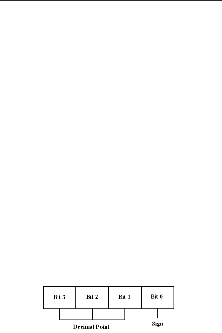
5-42
ADAM 4000 Series User’s Manual
4018M
@AARNNNN
Name Read Record Content command
Description Request the content of record NNNN stored in the analog
input data logger at address AA.
Syntax @AARNNNN (cr)
@ is a delimiter character.
AA (range 00-FF) represents the 2-character hexadecimal
address of an analog input data logger.
R identifies the Read Record Content command.
NNNN represents the 4-character hexadecimal number of
stored record index. Its value is from 0 to (total record
number - 1).
(cr) is the terminating character, carriage return (0Dh).
NOTE:
NNNN is from 0 to 9470 for Standard Mode.
NNNN is from 0 to 4599 for Event Mode.
NNNN is from 0 to 7299 for Mixed Mode. (0-4999 are
data records, 5000-7299 are event records)
Response !AACDHHHH(cr) if the returned data are data records.
!AACDHHHHTTTTTTTT(cr) if the returned data are
event records.
! is a delimiter character indicating a valid command was
received.
AA (range 00-FF) represents the 2-character hexadecimal
address of an analog input module.
C represents the channel index. Its value is from 0 to 7.
D represents the 4-bit binary number. Bit 0 represents the
sign of the number HHHH. ‘0’ means positive. ‘1’ means
negative. Bits 1~3 represents the decimal point of the
number HHHH.

Chapter 5
5-43
ADAM 4000 Series User’s Manual
4018M
@AARNNNN
HHHH represents the 4-character hexadecimal number of
returned record stored in the analog input data logger at
address AA.
TTTTTTTT represents elapsed time.
(cr) is the terminating character, carriage return (0Dh).
Example command: @F3R1000(cr)
response: !F30799AA00001000(cr)
The command requests the analog input data logger at
address F3 to return its contents in the 1001st record.
The returned content is valid. The event data number is
- 39.338 for channel 0 in the 4096 seconds from the start of
the module.

5-44
ADAM 4000 Series User’s Manual
4018M
@AAACSDHHHHTEIIII
Name Set Alarm Limit command
Description Set high/low alarm limits for the channel C in the analog
input data logger at address AA.
Syntax @AAACSDHHHHTEIIII(cr)
@ is a delimiter character
AA (range 00-FF) represents the 2-character hexadecimal
address of an analog input data logger.
A is the Set Alarm Limit command.
C represents the channel index. Its value is from 0 to 7.
S represents the sign of the high alarm limit.
‘+’ is for positive, and ‘-’ is for negative.
D represents the decimal point of the high alarm limit. Its
value is from 0 to 5.
HHHH represents the 4-character hexadecimal number of
high alarm limit.
T represents the sign of the low alarm limit.
‘+’ is for positive, and ‘-’ is for negative.
E represents the decimal point of the low alarm limit. Its
value is from 0 to 5.
IIII represents the 4-character hexadecimal number of low
alarm limit.
(cr) is the terminating character, carriage return (0Dh).
Response !AA(cr) if the command is valid.
?AA(cr) if an invalid parameter was entered. There is no
response if the module detects a syntax error or
communication error or if the specified address does not
exist.
! is a delimiter character indicating a valid command was
received.
? is a delimiter character indicating the command was
invalid.
AA (range 00-FF) represents the 2-character hexadecimal
address of an analog input data logger.
(cr) is the terminating character, carriage return (0Dh).

Chapter 5
5-45
ADAM 4000 Series User’s Manual
4018M
@AAACSDHHHHTEIIII
Example command: @EFA0+20400+20100(cr)
response: !EF(cr)
The command sets channel 0 of the analog input data
logger at address EF as such:
high alarm limit = 10.24
low alarm limit = 2.56
The response indicates the command was received.

5-46
ADAM 4000 Series User’s Manual
4018M
@AABC
Name Read Alarm Limit command
Description Request the alarm limits for the specified channel in the
analog input data logger at address AA.
Syntax @AABC(cr)
@ is a delimiter character.
AA (range 00-FF) represents the 2-character hexadecimal
address of an analog input data logger.
B is the Read Alarm Limit command.
C represents the channel index. Its value is from 0 to 7.
(cr) is the terminating character, carriage return (0Dh).
Response !AASDHHHHTEIIII
! is a delimiter character indicating a valid command was
received.
AA (range 00-FF) represents the 2-character hexadecimal
address of an analog input data logger.
S represents the sign of the high alarm limit.
‘+’ is for positive, and ‘-’ is for negative.
D represents the decimal point of the high alarm limit. Its
value is from 0 to 5.
HHHH represents the 4-character hexadecimal number of
high alarm limit.
T represents the sign of the low alarm limit.
‘+’ is for positive, and ‘-’ is for negative.
E represents the decimal point of the low alarm limit. Its
value is from 0 to 5.
IIII represents the 4-character hexadecimal number of low
alarm limit.
(cr) is the terminating character, carriage return (0Dh).

Chapter 5
5-47
ADAM 4000 Series User’s Manual
5.3 Digital I/O, Alarm and Event Command Set
Command Syntax
Command Name Description I/O Module
@AADI Read Digital I/O and
Alarm Status
The addressed module
returns the state of its digital
input and digital output
channels and the status of its
alarm
4011, 4011D,
4012, 4016
@AADO(data) Set Digital Output
Values
Set the values of the
module's digital outputs (ON
or OFF
)
4011, 4011D,
4012, 4016
@AAEAT Enable Alarm Enables the alarm in either
Momentary or Latching mode
4011, 4011D,
4012, 4016
@AAHI(data) Set High Alarm Value Downloads the High alarm
limit value
4011, 4011D,
4012, 4016
@AALO(data) Set Low Alarm Value
Downloads the Low alarm
limit value
4011, 4011D,
4012, 4016
@AADA Disable Alarm Disables all alarm functions 4011, 4011D,
4012, 4016
@AACA Clear Latch Alarm Resets the module's Latch
alarm to zero
4011, 4011D,
4012, 4016
@AARH Read High Alarm
Value
Ask the addressed module to
return its high alarm value
4011, 4011D,
4012, 4016
@AARL Read Low Alarm
Value
Ask the addressed module to
return its low alarm value
4011, 4011D,
4012, 4016
@AARE Read Event Counter Ask the addressed module to
return its event counter value
4011, 4011D,
4012
@AACE Clear Event Counter Reset the module's event
counter to zero
4011, 4011D,
4012

5-48
ADAM 4000 Series User’s Manual
4011, 4011D, 4012, 4016
@AADI
Name Read Digital I/O and Alarm State
Description The addressed analog input module is instructed to return
the value of its digital input and output channels and the
state of its alarm (Momentary or Latching).
Syntax @AADI(cr)
@ is a delimiter character.
AA (range 00-FF) represents the 2-character hexadecimal
address of an analog input module.
DI is the Read Digital I/O and Alarm Status command.
(cr) represents terminating character, carriage return (0Dh).
Response ADAM-4011/4011D/4012:
!AASOOII(cr) if the command was valid
ADAM-4016:
!AASOO00(cr) if the command was valid
There is no response if the module detects a syntax error or
communication error or if the specified address does not
exist.
! delimiter character indicates a valid command was
received.
AA represents the 2-character hexadecimal address of the
responding analog input module.
S hexadecimal number that represents the alarm state (0h =
disabled, 1h = MOMENTARY mode enabled, 2h =
LATCH mode enabled).
OO
For ADAM-4011/4011D/4012: it is a hexadecimal number
representing the Digital Output port’s channel 0 and 1
status (00h = D/O channels 0 and 1 are both OFF, 01h =
channel 0 is ON, channel 1 is OFF, 02h = channel 0 is OFF,
channel 1 is ON, 03h = channel 0 and 1 are both ON).
For ADAM-4016: it is a hexadecimal number representing
the status of the four digital output channels. The
corresponding table is show in the following table:

Chapter 5
5-49
ADAM 4000 Series User’s Manual
4011, 4011D, 4012, 4016
@AADI
Status Code
DO0 001 002 003
OO OFF OFF OFF OFF
O1 OFF OFF OFF ON
O2 OFF OFF ON OFF
O3 OFF OFF ON ON
O4 OFF ON OFF OFF
O5 OFF ON OFF ON
O6 OFF ON ON OFF
O7 OFF ON ON ON
O8 ON OFF OFF OFF
O9 ON OFF OFF ON
OA ON OFF ON OFF
OB ON OFF ON ON
OC ON ON OFF OFF
OD ON ON OFF ON
OE ON ON ON OFF
OF ON ON ON ON
II is a hexadecimal number representing the Digital input
port’s channel status (00h = D/I channel is Low, 01h =
channel is High).
(cr) represents terminating character, carriage return (0Dh).
Example command: @15DI(cr)
response: !510001(cr)
The analog input module at address 15h is instructed to
return digital I/O data and alarm status.
The module responds that both digital output channels are
OFF, digital input is HIGH, and alarm state is Momentary.

5-50
ADAM 4000 Series User’s Manual
4011, 4011D, 4012, 4016
@AADO
Name Set Digital Output command
Description Sets the values of the module’s digital outputs (ON or OFF).
Syntax @AADO(data)(cr)
@ is a delimiter character.
AA (range 00-FF) represents the 2-character hexadecimal
address of an analog input module.
DO is the Set Digital Output command.
(data) is the two-character parameter that sets the state for
the digital output bits of the module, as shown below:
For ADAM-4011/4011D/4012:
00 all D/O bits are OFF
01 DO0 is ON, DO1 is OFF
02 DO0 is OFF, DO1 is ON
03 all bits are ON
For ADAM-4016:
00 DO0 and DO1 are OFF
01 DO0 is ON, DO1 is OFF
02 DO0 is OFF, DO1 is ON
03 DO0 and DO1 are ON
10 DO2 and DO3 are OFF
11 DO2 is ON, DO3 is OFF
12 DO2 is OFF, DO3 is ON
13 DO2 and DO3 are ON
(cr) represents terminating character, carriage return (0Dh).
Response !AA(cr) if the command was valid.
?AA(cr) if an invalid parameter was entered.
There is no response if the module detects a syntax error or
communication error or if the specified address does not exist
! delimiter character indicates a valid command was received.
? delimiter character indicates the command was invalid.
AA represents the 2-character hexadecimal address of the
responding analog input module.
(cr) represents terminating character, carriage return (0Dh).

Chapter 5
5-51
ADAM 4000 Series User’s Manual
4011, 4011D, 4012, 4016
@AADO
Example command: @05DO01(cr)
response: !05(cr)
The analog input module at address 05h is instructed to set
digital output channel 1 to ON and digital output channel 2
to OFF. The module confirms the settings.

5-52
ADAM 4000 Series User’s Manual
4011, 4011D, 4012, 4016
@AAEAT
Name Enable Alarm command
Description The addressed analog input module is instructed to enable
its alarm in either Latching or Momentary mode.
Syntax @AAEAT(cr)
@ is a delimiter character.
AA (range 00-FF) represents the 2-character hexadecimal
address of an analog input module.
EA is the Enable Alarm command.
T indicates alarm type and can have the value M =
Momentary alarm state, or L = Latching alarm state.
(cr) represents terminating character, carriage return (0Dh).
Response !AA(cr) if the command was valid.
There is no response if the module detects a syntax error or
communication error or if the specified address does not
exist.
! delimiter character indicates a valid command was
received.
AA represents the 2-character hexadecimal address of the
responding analog input module.
(cr) represents terminating character, carriage return (0Dh).
Example command: @03EAL(cr)
response: !03(cr)
The analog input module at address 03h is instructed to
enable its alarm in Latching mode.
The module confirms that the command has been received.
NOTICE: An analog input module requires a maximum of 2 seconds after
it received an Enable Alarm command to let the settings take
effect . During this interval, the module can not be addressed to
perform any other actions.

Chapter 5
5-53
ADAM 4000 Series User’s Manual
4011, 4011D, 4012, 4016
@AAHI
Name Set High Alarm Limit command
Description Downloads high alarm limit value into the addressed
module.
Syntax @AAHI(data)(cr)
@ is a delimiter character.
AA (range 00-FF) represents the 2-character hexadecimal
address of an analog input module.
HI is the Set High Limit command.
(data) represents the value of the desired high limit setting.
The format is always engineering units.
(cr) represents terminating character, carriage return (0Dh).
Response !AA(cr) if the command was valid.
There is no response if the module detects a syntax error or
communication error or if the specified address does not
exist.
! delimiter character indicates a valid command was
received.
AA represents the 2-character hexadecimal address of the
responding analog input module.
(cr) represents terminating character, carriage return (0Dh).
Example command: @04HI+080.00(cr)
response: !04(cr)
Presume the analog input module at address 04h is
configured to accept T-type thermocouple input. The
command will set the High alarm limit to 80℃.
The module responds that the command has been received.
NOTICE: An analog input module requires a maximum of 2 seconds after
it received an Set High Alarm command to let the settings take
effect . During this interval, the module can not be addressed to
perform any other actions.

5-54
ADAM 4000 Series User’s Manual
4011, 4011D, 4012, 4016
@AALO
Name Set Low Alarm Limit command
Description Downloads Low alarm limit value into the addressed
module.
Syntax @AALO(data)(cr)
@ is a delimiter character.
AA (range 00-FF) represents the 2-character hexadecimal
address of an analog input module.
LO is the Set Low Limit command.
(data) represents the value of the desired low limit setting.
The format is always engineering units.
(cr) represents terminating character, carriage return (0Dh).
Response !AA(cr) if the command was valid.
There is no response if the module detects a syntax error or
communication error or if the specified address does not
exist.
! delimiter character indicates a valid command was
received.
AA represents the 2-character hexadecimal address of the
responding analog input module.
(cr) represents terminating character, carriage return (0Dh).
Example command: @04LO-020.00(cr)
response: !04(cr)
Presume the analog input module at address 04h is
configured to accept T-type thermocouple input. The
command will set the Low alarm limit to -20 ℃.
The module responds that the command has been received.
NOTICE: An analog input module requires a maximum of 2 seconds after
it received an Set Low Alarm command to let the settings take
effect . During this interval, the module can not be addressed to
perform any other actions.

Chapter 5
5-55
ADAM 4000 Series User’s Manual
4011, 4011D, 4012, 4016
@AADA
Name Disable Alarm command
Description Disables all alarm functions of the addressed analog input
module.
Syntax @AADA(cr)
@ is a delimiter character.
AA (range 00-FF) represents the 2-character hexadecimal
address of an analog input module.
DA is the Disable Alarm command.
(cr) represents terminating character, carriage return (0Dh).
Response !AA(cr) if the command was valid.
There is no response if the module detects a syntax error or
communication error or if the specified address does not
exist.
! delimiter character indicates a valid command was
received.
AA represents the 2-character hexadecimal address of the
responding analog input module.
(cr) represents terminating character, carriage return (0Dh).
Example command: @07DA (cr)
response: !07(cr)
The analog input module at address 07h is instructed to
disable all alarm functions.
The module confirms it alarm functions have been disabled.
NOTICE: An analog input module requires a maximum of 2 seconds after
it received an Disable Alarm command to let the settings take
effect . During this interval, the module can not be addressed to
perform any other actions.

5-56
ADAM 4000 Series User’s Manual
4011, 4011D, 4012, 4016
@AACA
Name Clear Latch Alarm command
Description Both alarm states (High and Low) of the addressed analog
input module are set to OFF, no alarm.
Syntax @AACA(cr)
@ is a delimiter character.
AA (range 00-FF) represents the 2-character hexadecimal
address of an analog input module.
CA is the Clear Latch Alarm command.
(cr) represents terminating character, carriage return (0Dh).
Response !AA(cr) if the command was valid.
There is no response if the module detects a syntax error or
communication error or if the specified address does not
exist.
! delimiter character indicates a valid command was
received.
AA represents the 2-character hexadecimal address of the
responding analog input module.
(cr) represents terminating character, carriage return (0Dh).
Example command: @05CA(cr)
response: !05(cr)
The analog input module at address 05h is instructed to set
both alarm states (High and Low) to OFF.
The module confirms it has done so accordingly.

Chapter 5
5-57
ADAM 4000 Series User’s Manual
4011, 4011D, 4012, 4016
@AARH
Name Read High Alarm Limit command
Description The addressed module is asked to return its High alarm
limit value.
Syntax @AARH(cr)
@ is a delimiter character.
AA (range 00-FF) represents the 2-character hexadecimal
address of an analog input module.
RH is the Read High Alarm Limit command.
(cr) represents terminating character, carriage return (0Dh).
Response !AA(data)(cr) if the command was valid.
There is no response if the module detects a syntax error or
communication error or if the specified address does not
exist.
! delimiter character indicates a valid command was
received.
AA represents the 2-character hexadecimal address of the
responding analog input module.
(data) is the value of the High alarm limit in engineering
units.
(cr) represents terminating character, carriage return (0Dh).
Example command: @07RH(cr)
response: !07+2.0500(cr)
Presume the analog input module at address 07h is
configured to accept 5 V input. The command instructs the
module to return it High alarm limit value. The module
responds its High alarm limit value is 2.0500 V.

5-58
ADAM 4000 Series User’s Manual
4011, 4011D, 4012, 4016
@AARL
Name Read Low Alarm Limit command
Description The addressed module is asked to return its Low alarm limit
value.
Syntax @AARL(cr)
@ is a delimiter character.
AA (range 00-FF) represents the 2-character hexadecimal
address of an analog input module.
RL is the Read Low Alarm Limit command.
(cr) represents terminating character, carriage return (0Dh).
Response !AA(data)(cr) if the command was valid.
There is no response if the module detects a syntax error or
communication error or if the specified address does not
exist.
! delimiter character indicates a valid command was
received.
AA represents the 2-character hexadecimal address of the
responding analog input module.
(data) is the value of the Low alarm limit in engineering
units.
(cr) represents terminating character, carriage return (0Dh).
Example command: @05RL(cr)
response: !05-0.3750(cr)
Presume the analog input module at address 05h is
configured to accept 1 V input. The command instructs the
module to return it Low alarm limit value. The module
responds its Low alarm limit value is -0.3750 V.

Chapter 5
5-59
ADAM 4000 Series User’s Manual
4011, 4011D, 4012
@AARE
Name Read Event Counter command
Description The addressed module is instructed to return its event
counter value.
Syntax @AARE(cr)
@ is a delimiter character.
AA (range 00-FF) represents the 2-character hexadecimal
address of an analog input module.
RE is the Reads Event Counter command.
(cr) represents terminating character, carriage return (0Dh).
Response !AA(data)(cr) if the command was valid.
There is no response if the module detects a syntax error or
communication error or if the specified address does not
exist.
! delimiter character indicates a valid command was
received.
AA represents the 2-character hexadecimal address of the
responding analog input module.
(data) represents the stored value, from ‘00000’ to ‘65535’
(The max value that can be held by the counter register is
65535). The number 65535 is held when the actual total
counts exceed this number.
(cr) represents terminating character, carriage return (0Dh).
Example command: @08RE(cr)
response: !0832011(cr)
The command instructs the module at address 08h to return
its counter value. The module responds that its counter
value equals 32011.

5-60
ADAM 4000 Series User’s Manual
4011, 4011D, 4012
@AACE
Name Clear Event Counter command
Description The addressed module is instructed to reset its event
counter to zero.
Syntax @AACE(cr)
@ is a delimiter character.
AA (range 00-FF) represents the 2-character hexadecimal
address of an analog input module.
CE is the Clear Event Counter command.
(cr) represents terminating character, carriage return (0Dh).
Response !AA(cr) if the command was valid.
There is no response if the module detects a syntax error or
communication error or if the specified address does not
exist.
! delimiter character indicates a valid command was
received.
AA represents the 2-character hexadecimal address of the
responding analog input module.
(cr) represents terminating character, carriage return (0Dh).
Example command: @09CE(cr)
response: !09(cr)
The command instructs the module at address 09h to set its
event counter to zero. The module responds that its counter
has been reset.

Chapter 5
5-61
ADAM 4000 Series User’s Manual
5.4 Excitation Voltage Output Command Set
Command S
y
ntax
Command Name
Description
I/O module
$AA6 Get Excitation Voltage
Output Value
Returns either last value sent
to specified module by $AA7
command, or start-up output
voltage.
4016
$AA7 Excitation Voltage
Output
Direct output excitation
voltage data to a specified
module
4016
$AAS Start-up Voltage Output
Configuration
Stores a default value in a
specified module. The output
value will take effect upon
startup.
4016
$AAE Trim Calibration Trims specified module a
number of units up/down
4016
$AAA Zero Calibration Tells the module to store
parameters for zero
calibration
4016
$AAB Span Calibration Tells the module to store
parameters for span
calibration
4016

5-62
ADAM 4000 Series User’s Manual
4016
$AA6
Name Get Excitation Voltage Output Value command
Description The addressed strain gauge input module is instructed to
return the latest output value it received from Excitation
Voltage Output command. If the module hasn’t received an
Excitation Voltage Output command since startup, it will
return its Start-up Output value.
Syntax $AA6(cr)
$ is a delimiter character.
AA (range 00-FF) represents the 2-character hexadecimal
address of the strain gauge input module.
6 is the Get Excitation Voltage Output command.
(cr) is the terminating character, carriage return (0Dh)
Response !AA(data)(cr) if the command is valid.
?AA(cr) if an invalid command was issued.
There is no response if the module detects a syntax error or
communication error or if the specified address does not
exist.
! delimiter character indicates a valid command was
received.
? delimiter character indicates the command was invalid.
AA (range 00-FF) represents the 2-character hexadecimal
address of the strain gauge input module.
(data) is the value that is returned by analog output channel.
The format of the data is in engineering unit.
(cr) is the terminating character, carriage return (0Dh)
Example command: $0A6(cr)
response: !0A+03.000(cr)
The command tells the strain gauge input module at address
0Ah to return the last excitation voltage output value it
received from an Excitation Voltage Output command. The
strain gauge input module returns the value +03.000V.

Chapter 5
5-63
ADAM 4000 Series User’s Manual
4016
$AA7
Name Excitation Voltage Output command
Description Send a value to the analog output channel of the addressed
strain gauge input module. Upon receipt, the analog output
channel will output this value.
Syntax $AA7(data)(cr)
$ is a delimiter character.
AA (range 00-FF) represents the 2-character hexadecimal
address of the strain gauge input module.
7 is the Excitation Voltage Output command.
(data) is the value that has to be output through the analog
output channel. The data format is engineering unit and the
range is between 0 ~ 10 V.
(cr) is the terminating character, carriage return (0Dh)
Response !AA(cr) if the command is valid.
?AA(cr) if a value was sent that is out of range.
There is no response if the module detects a syntax error or
communication error or if the specified address does not
exist.
! delimiter character indicates a valid command was
received.
? delimiter character indicates the command was invalid.
AA (range 00-FF) represents the 2-character hexadecimal
address of the strain gauge input module.
(cr) is the terminating character, carriage return (0Dh)
Example command: $337+05.000(cr)
response: !33(cr)
The command sends the value +05.000V to the analog
output channel of the strain gauge input module at address
33h. The module responds that the command is valid. Its
output data format is in engineering unit, the value is
+05.000V.

5-64
ADAM 4000 Series User’s Manual
4016
$AAS
Name Start-up Voltage Output Configuration command
Description Stores the present analog output value of the strain gauge
input module with address AA in the module’s non-volatile
register. The output value will take effect upon start-up or
after a brownout.
Syntax $AAS(cr)
$ is a delimiter character.
AA (range 00-FF) represents the 2-character hexadecimal
address of the strain gauge input module whose analog
output is to be set.
S is the Start-up Voltage Output Configuration command.
(cr) is the terminating character, carriage return (0Dh).
Response !AA(cr) if the command is valid.
?AA(cr) if an invalid command was issued.
There is no response if the module detects a syntax error or
communication error or if the specified address does not
exist.
! delimiter character indicates a valid command was
received.
? delimiter character indicates the command was invalid.
AA (range 00-FF) represents the 2-character hexadecimal
address of the strain gauge input module.
(cr) is the terminating character, carriage return (0Dh).
NOTICE: A strain gauge input module requires a maximum of 6
milliseconds after it received a Startup Voltage Output
Configuration command to let the settings take effect. During
this interval, the module can not be addressed to perform any
other actions.

Chapter 5
5-65
ADAM 4000 Series User’s Manual
4016
$AAS
Example command: $0AS(cr)
response: !0A(cr)
Presume the present output value of the output channel of
the strain gauge input module with address 0A is +05.000V.
The command tells the module store the present output
value, in its non-volatile memory. When the module is
powered up or reset, its default output value will be
+05.000V. The response of the strain gauge input module
indicates that the command has been received.

5-66
ADAM 4000 Series User’s Manual
4016
$AAE
Name Trim Calibration command
Description Trims the output voltage of the strain gauge input module a
specified number of units up or down.
Syntax $AAE(number of counts)(cr)
$ is a delimiter character.
AA (range 00-FF) represents the 2-character hexadecimal
address of the strain gauge input module to be calibrated.
E is the Trim Calibration command.
(number of counts) is the 2-character two’s complement
hexadecimal value that represents the number of counts by
which to increase or decrease the output voltage. Each
count equals approximately 1mV. Values range from 00 to
7F and from 80 to FF, where 00 represents 0 counts, 7F
represents 127 counts, 80 represents -128 counts and FF
represents -1 counts. Negative values decrease and positive
values increase the output voltage according to the number
of counts.
(cr) is the terminating character, carriage return (0Dh).
Response !AA(cr) if the command is valid.
There is no response if the module detects a syntax error or
communication error or if the specified address does not
exist.
! delimiter character indicates a valid command was
received.
AA (range 00-FF) represents the 2-character hexadecimal
address of the strain gauge input module.
(cr) is the terminating character, carriage return (0Dh).
Example command: $07E14(cr)
response: !07
The command tells the analog output of the strain gauge
input module at address 07h to increase its output value by
20 (14h) counts which is approximately 20 mV. The strain
gauge input module confirms the increase. In order to
perform this trim calibration, a voltmeter should be
connected to the module’s output. (See also the zero
calibration command and span calibration command of the
strain gauge input module and Chapter 8, Calibration, for a
detailed description.)

Chapter 5
5-67
ADAM 4000 Series User’s Manual
4016
$AAA
Name Zero Calibration command
Description Stores the voltage output value of the addressed strain
gauge input module as zero voltage reference.
Syntax $AAA(cr)
$ is a delimiter character.
AA (range 00-FF) represents the 2-character hexadecimal
address of the strain gauge input module whose output
channel is to be calibrated.
A is the Zero Calibration command.
(cr) is the terminating character, carriage return (0Dh)
Response !AA(cr) if the command is valid.
?AA(cr) if an invalid command was issued.
There is no response if the module detects a syntax error or
communication error or if the specified address does not
exist.
! delimiter character indicates a valid command was
received.
? delimiter character indicates the command was invalid.
AA (range 00-FF) represents the 2-character hexadecimal
address of the strain gauge input module.
(cr) is the terminating character, carriage return (0Dh).
Before issuing the Zero Calibration command, the analog
output should be trimmed to the correct value with the
Trim Calibration command. A voltmeter should be
connected to the module’s output channel. (See also the
strain gauge input module’s Trim Calibration command
and Chapter 8, Calibration, for a detailed description.)

5-68
ADAM 4000 Series User’s Manual
4016
$AAB
Name Span Calibration command
Description Stores the voltage output value of the addressed strain
gauge input module as 10V reference.
Syntax $AAB(cr)
$ is a delimiter character.
AA (range 00-FF) represents the 2-character hexadecimal
address of the strain gauge input module whose output
channel is to be calibrated.
B is the Span Calibration command.
(cr) is the terminating character, carriage return (0Dh).
Response !AA(cr) if the command is valid.
?AA(cr) if an invalid command was issued.
There is no response if the module detects a syntax error or
communication error or if the specified address does not
exist.
! delimiter character indicates a valid command was
received.
? delimiter character indicates the command was invalid.
AA (range 00-FF) represents the 2-character hexadecimal
address of the strain gauge input module.
(cr) is the terminating character, carriage return (0Dh).
Before issuing the Span Calibration command, the analog
output should be trimmed to the correct value with the
Trim Calibration command. A voltmeter should be
connected to the module’s output channel. (See also the
strain gauge input module’s Trim Calibration command
and Chapter 8, Calibration, for a detailed description.)
Analog Output Module Command Set 6

Analog Output Module Command Set
6-
2
ADAM 4000 Series User’s Manual
6.1 Analog Output Module Command for ADAM-4021
Command S
y
ntax
Command Name Description
I/O Module
%AANNTTCCFF Configuration Sets the address, output range,
baud rate, data format, slew
rate and/or checksum status
4021
#AA(data) Analog Data Out Directs output data to a
specified module
4021
$AA4 Start-Up Output
Current or Voltage
Configuration
Stores a default output value in
a specified module. The
output value will take effect
upon startup
4021
$AA3
(
number of counts
)
Trim Calibration Trims specified module a
number of units up/down
4021
$AA0 4 mA Calibration Tells the module to store
parameters for 4mA Calibration
4021
$AA1 20 mA Calibration
Tells the module to store
parameters for 20 mA
Calibration
4021
$AA2 Configuration
Status
Reads the configuration of
specified module
4021
$AA6 Last Value
Readback
Returns either last value sent to
specified module by #AA
command, or start-up output
current/volta
g
e
4021
$AA8 Current Readback Returns measured value of the
current/voltage flowing through
current loop
4021
$AA5 Reset Status Checks if module has been
reset since the last $AA5
command
4021
$AAF Read Firmware
Version
Returns the firmware version
code from the specified analog
output module
4021
$AAM Read Model
Name
Return the module name from
specified analo
g
output module
4021
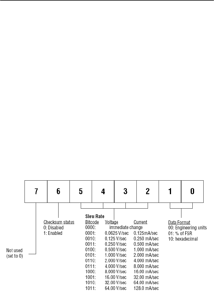
Chapter 6
6-
3
ADAM 4000 Series User’s Manual
%AANNTTCCFF
Name Configuration command
Description Sets address, input range, baud rate, data format, checksum
status, and/or integration time for an analog output module.
Syntax %AANNTTCCFF(cr)
% is a delimiter character.
AA (range 00-FF) represents the 2-character hexadecimal
address that is to be configured.
NN represents the new hexadecimal address of the analog
output module. Range is from 00h to FFh.
TT represents the type codes (output range codes).
(See Table 6-2 on next page)
CC represents the baud rate codes.
(See Table 6-1 on next page)
FF is a hexadecimal number that equals to 8-bit parameter
representing the status of data format, slew rate, and
checksum. The layout of the 8-bit parameter is shown in
Figure 6-1. Bit 7 is not used and must be set to 0.
(cr) is the terminating character, carriage return (0Dh).
Figure 6-1 Data format for FF (8-bit parameter)
Note: Only ADAM-4021 supports “% of FSR” and “two’s complement of
hexadecimal” Data Format.
4021

Analog Output Module Command Set
6-
4
ADAM 4000 Series User’s Manual
%AANNTTCCFF
Response !AA(cr) if the command is valid.
?AA(cr) if an invalid parameter was entered or the INIT*
terminal was not grounded when changing baud rate or
checksum settings was attempted.
There is no response if the module detects a syntax or
communication error, or even if the specified address does
not exist.
! delimiter character indicates that a valid command is
received.
? delimiter character indicates that the command is invalid.
AA (range 00-FF) represents the 2-character hexadecimal
address of an analog output module.
(cr) is the terminating character, carriage return (0Dh).
Table 6-1 Baud Rate Codes
Baud Rate
Code
(
Hex
)
Baud Rate
03 1200 bps
04
2400 bps
05
4800
bps
06
9600 bps
07
19.2 Kbps
08 38.4 Kbps
Table 6-2 Output Range Codes (Type Codes)
Output Ran
g
e Code
(
Hex
)
Output Ran
g
e
for ADAM-4021
30
0 to 20 mA
31 4 to 20 mA
32
0 to 10 V
NOTICE: An analog output module requires a maximum of 20
milliseconds to perform auto calibration and ranging after it is
reconfigured. During this time span, the module can not be
addressed to perform any other actions.
NOTICE: All configuration parameters can be changed dynamically,
except the checksum and baud rate parameters. They can only
be altered when the INIT* terminal is grounded. (Refer to Baud
rate and Checksum in Chapter 2).
4021

Chapter 6
6-
5
ADAM 4000 Series User’s Manual
%AANNTTCCFF
Example command: %310A310610(cr)
response: !24(cr)
The analog input module is configured from addresses 31h
to a new address 0Ah, output range 4 to 20 mA, baud rate
9600, engineering units data format, a slew rate of 1.0
mA/sec and no checksum checking.
The response indicates that the command has been
received.
4021

Analog Output Module Command Set
6-
6
ADAM 4000 Series User’s Manual
#AA
Name Analog Data Out command
Description Send a value to the address of analog output module. Then,
the analog output module will output this value.
Syntax #AA(data)(cr)
# is a delimiter character.
AA (range 00-FF) represents the 2-character hexadecimal
address of an analog output module.
(data) is the value that has to be outputted through the
analog output module. The Range and value depend on the
module’s configured data format. The possible formats are
engineering units or % of FSR or hexadecimal. (Please
refer to Appendix B, Data Formats and I/O Ranges.)
(cr) is the terminating character, carriage return (0Dh).
Response >(cr) if the command was valid.
?AA(cr) if the sent value was out of range. Note that when
the analog output module receives such a value, it will try
to use a value which is close to the one received and within
the module’s configured range.
There is no response if the module detects a syntax or
communication error, or even if the specified address does
not exist.
> is a delimiter character.
? delimiter character indicates that the command is invalid.
AA (range 00-FF) represents the 2-character hexadecimal
address of an analog output module.
(cr) is the terminating character, carriage return (0Dh).
4021

Chapter 6
6-
7
ADAM 4000 Series User’s Manual
#AA
Example command: #3315.000(cr)
response: >(cr)
The command sends the value 15 mA, which is converted
to engineering units, to the address 33h of the analog output
module. The analog output module responds with an output
value of 15 mA which represents a valid command.
command: #0A+030.00(cr)
response: >(cr)
The module is configured for an output range of 4 to 20 mA
and a percent of span data format. The command sends the
value 8.8 mA (4 mA + 0.30 x 16 mA = 8.8 mA) which is
30% of the span to the address 0Ah of analog output
module. The analog output module responds with an output
value of 8.8 mA which represents a valid command.
command: #1B7FF(cr)
response: >(cr)
The command sends the hexadecimal value 7FF to the
analog output module at address 1Bh. The module is
configured to a 0 to 20 mA output range and a hexadecimal
data format. It will output with a value of 10 mA
((7FFH/FFFH) x 20 mA = 10 mA).
4021

Analog Output Module Command Set
6-
8
ADAM 4000 Series User’s Manual
$AA4
Name Start-up Voltage/Current Output Configuration command
Description Stores the present output value of an analog output module
at address AA in the module’s non-volatile register. The
output value will take effect at start-up or after a brownout.
Syntax $AA4(cr)
$ is a delimiter character.
AA (range 00-FF) represents the 2-character hexadecimal
address of the analog output module whose output current
is to be set.
4 is the Start-up Output Current Configuration command.
(cr) is the terminating character, carriage return (0Dh).
Response !AA(cr) if the command is valid.
?AA(cr) if an invalid command was issued.
There is no response if the module detects a syntax or
communication error, or even if the specified address does
not exist.
! delimiter character indicates that a valid command was
received.
? delimiter character indicates that the command was
invalid.
AA (range 00-FF) represents the 2-character hexadecimal
address of the analog output module.
(cr) is the terminating character, carriage return (0Dh).
Example command: $0A4(cr)
response: !0A(cr)
Presume the present output value of the analog output
module at address 0A is 9.4 mA. The command tells the
analog output module to store the present output value into
non-volatile memory. When the module is at start-up or
reset, its default output value will be 9.4mA. The response
of the analog output module indicates that the command
has been received.
NOTICE: An analog output module requires a maximum of 6 milli-seconds
after it received a Startup Voltage/Current Output Configuration
command to let the settings take effect . During this interval, the
module can not be addressed to perform any other actions.
4021

Chapter 6
6-
9
ADAM 4000 Series User’s Manual
$AA3
Name Trim Calibration command
Description Trim the address of analog output module for a specific
number of units up or down.
Syntax $AA3(number of counts)(cr)
$ is a delimiter character.
AA (range 00-FF) represents the 2-character hexadecimal
address which is to be calibrated.
3 is the Trim Calibration Command.
(number of counts) is the 2-character two’s complement
hexadecimal value that represents the number of counts
increasing or decreasing the output current. Each count
equals to approximately 1.5 μA. Values range from 00 to
5F and A1 to FF (hexadecimal). The 00 represents 0 counts,
5F represents +95 counts, A1 represents -95 counts and FF
represents -1 count. Negative values decrease the output
current according to the number of counts. On the other
hand, the positive values do the opposite.
(cr) is the terminating character, carriage return (0Dh).
Response !AA(cr) if the command is valid.
There is no response if the module detects a syntax or
communication error, or even if the specified address does
not exist.
! delimiter character indicates that a valid command was
received
AA (range 00-FF) represents the 2-character hexadecimal
address of the analog output module.
(cr) is the terminating character, carriage return (0Dh).
4021

Analog Output Module Command Set
6-
10
ADAM 4000 Series User’s Manual
$AA3
Example command: $07314(cr)
response: !07(cr)
The command tells the analog output module at address
07h to increase its output value by 20 (14h) counts which
are approximately 30 μA.
The analog output module confirms the increase.
In order to perform this trim calibration, a millimeter or a
resistor and voltmeter should be connected to the module’s
output. (Please see the 4 mA Calibration command and 20
mA Calibration command of the analog output module’s
command set. Please also refer to Chapter 8, Calibration
for a detailed description.)
4021

Chapter 6
6-
11
ADAM 4000 Series User’s Manual
$AA0
Name 4 mA Calibration command
Description Stores the current output value 4 mA for reference in the
specified address in analog output module.
Syntax $AA0(cr)
$ is a delimiter character.
AA (range 00-FF) represents the 2-character hexadecimal
address whose data are to be sent.
0 is the 4 mA Calibration command.
(cr) is the terminating character, carriage return (0Dh).
Response !AA(cr) if the command was valid.
?AA(cr) if an invalid command was issued.
There is no response if the module detects a syntax or
communication error, or even if the specified address does
not exist.
! delimiter character indicates that a valid command was
received.
? delimiter character indicates that the command was
invalid.
AA (range 00-FF) represents the responding 2-character
hexadecimal address of the analog output module.
(cr) is the terminating character, carriage return (0Dh).
Before issuing the 4 mA Calibration command, the analog
output module should be trimmed to the correct value with
the Trim Calibration command. A millimeter or a resistor
and voltmeter should be connected to the module’s output.
(Please refer to the analog output module’s Trim
Calibration command and Chapter 8, Calibration, for a
detailed description.)
4021

Analog Output Module Command Set
6-
12
ADAM 4000 Series User’s Manual
$AA1
Name 20 mA Calibration command
Description Stores the current output value of the addressed analog
output module as 20 mA reference.
Syntax $AA1(cr)
$ is a delimiter character.
AA (range 00-FF) represents the 2-character hexadecimal
address whose data are to be sent.
1 is the 20 mA Calibration command.
(cr) is the terminating character, carriage return (0Dh).
Response !AA(cr) if the command was valid.
?AA(cr) if an invalid command was issued.
There is no response if the module detects a syntax or
communication error, or even if the specified address does
not exist.
! delimiter character indicates that a valid command was
received.
? delimiter character indicates that the command was
invalid.
AA (range 00-FF) represents the responding 2-character
hexadecimal address of the analog output module.
(cr) is the terminating character, carriage return (0Dh).
Before issuing the 20 mA Calibration command, the analog
output module should be trimmed to the correct value with
the Trim Calibration command. A millimeter or a resistor
and voltmeter should be connected to the module’s output.
(Please refer to the analog output module’s Trim
Calibration command and Chapter 8, Calibration, for a
detailed description.)
4021

Chapter 6
6-
13
ADAM 4000 Series User’s Manual
$AA2
Name Read Configuration Status command
Description Instruct the analog output module to return its configuration
data.
Syntax $AA2(cr)
$ is a delimiter character.
AA (range 00-FF) represents the 2-character hexadecimal
address for status reading.
2 is the Read Configuration Status command.
(cr) is the terminating character, carriage return (0Dh).
Response !AATTCCFF(cr) if the command is valid.
?AA(cr) if an invalid command was issued.
There is no response if the module detects a syntax or
communication error, or even if the specified address does
not exist.
! delimiter character indicates that a valid command was
received.
? delimiter character indicates that the command was
invalid.
AA (range 00-FF) represents the 2-character hexadecimal
address of an analog output module.
TT represents the type of code, which determines the
output range.
CC represents the baud rate code.
FF is a hexadecimal number that equals to 8-bit parameter
representing the data format, slew rate, and checksum
status.
(cr) is the terminating character, carriage return (0Dh)
Please refer to %AANNTTCCFF Configuration command
(Page 6-3 and 6-4) for TT, CC and FF parameter definition.
Example command: $452(cr)
response: !45300614(cr)
The command asks the analog output module at address
45h to send its configuration data.
The analog output module at address 45h responds with
output range 0 to 20 mA, baud rate 9600, engineering units
as the currently configured data format, slew rate 2 mA per
second, and no checksum checking.
4021

Analog Output Module Command Set
6-
14
ADAM 4000 Series User’s Manual
$AA6
Name Last Value Readback command
Description The analog output module is instructed to return the latest
output value that it has received from the Analog Data Out
command. If the module hasn’t received any Analog Data
Out commands since startup, it will return to its Start-up
Output value.
Syntax $AA6(cr)
$ is a delimiter character.
AA (range 00-FF) represents the 2-character hexadecimal
address whose value you want to return.
6 is the Last Value Readback command.
(cr) is the terminating character, carriage return (0Dh).
Response !AA(data)(cr) if the command was valid.
?AA(cr) if an invalid command was issued.
There is no response if the module detects a syntax or
communication error, or even if the specified address does
not exist.
! delimiter character indicates that a valid command was
received.
? delimiter character indicates that the command was
invalid.
AA (range 00-FF) represents the 2-character hexadecimal
address of the analog output module.
(data) is the value that is returned by the analog output
module. The format of the data depends on the module’s
configured data format.
(cr) is the terminating character, carriage return (0Dh).
Example command: $0A6(cr)
response: !0A03.000(cr)
The command requests the analog output module at address
0Ah to return the last output value that it has received from
an Analog Out command.
The analog output module returns the value 3.000 mA.
4021

Chapter 6
6-
15
ADAM 4000 Series User’s Manual
$AA8
Name Current Readback command
Description The addressed analog output module is instructed to
measure the current flowing through its current/voltage
loop and return the measured data in the module’s
configured data format. The value returned may be a rough
estimate of the real value.
Syntax $AA8(cr)
$ is a delimiter character.
AA (range 00-FF) represents the 2-character hexadecimal
address of the analog output module that you want to
retrieve the data from. The data are current/voltage loop.
8 is the Current feedback command.
(cr) is the terminating character, carriage return (0Dh).
Response !AA(data)(cr) if the command was valid.
?AA(cr) if an invalid command was issued.
There is no response if the module detects a syntax or
communication error, or even if the specified address does
not exist.
! delimiter character indicates that a valid command was
received.
? delimiter character indicates that the command was
invalid.
AA (range 00-FF) represents the 2-character hexadecimal
address of the analog output module.
(data) is the value returned by the analog output module.
(cr) is the terminating character, carriage return (0Dh).
Example command: $0A8(cr)
response: !0A18.773(cr)
The command tells the analog output module at address
0Ah to measure its current loop and return the measured
value.
The analog output module returns the value 18.773 mA.
4021

Analog Output Module Command Set
6-
16
ADAM 4000 Series User’s Manual
$AA5
Name Reset Status command
Description Checks the Reset Status of the analog output module to see
whether it has been reset since the last Reset Status
command was issued.
Syntax $AA5(cr)
$ is a delimiter character.
AA (range 00-FF) represents the 2-character hexadecimal
address of the analog output module who’s Reset Status is
to be returned.
5 is the Reset Status command.
(cr) is the terminating character, carriage return (0Dh).
Response !AAS(cr) if the command was valid.
?AA(cr) if an invalid command was issued.
There is no response if the module detects a syntax or
communication error, or even if the specified address does
not exist.
! delimiter character indicates that a valid command was
received.
? delimiter character indicates that the command was valid.
AA (range 00-FF) represents the 2-character hexadecimal
address of the analog output module.
S represents the Status bit which is returned by the analog
output module. If S=1, the module is in reset mode since a
Reset Status command had been issued already. If S=0, the
module has not been reset since the last Reset Status
command was not issued.
(cr) is the terminating character, carriage return (0Dh).
Example command: $395(cr)
response: !391(cr)
The analog output module at address 39h was reset or
powered up after the last execution of the Reset Status
command. When the command is executed once more, the
analog output module will reply with !390(cr)
4021

Chapter 6
6-
17
ADAM 4000 Series User’s Manual
$AAF
Name Read Firmware Version command
Description The command requests the analog output module at address
AA to return the version code of its firmware.
Syntax $AAF (cr)
$ is a delimiter character.
AA (range 00-FF) represents the 2-character hexadecimal
address that you want to access.
F is the Read Firmware Version command.
(cr) is the terminating character, carriage return (ODh).
Response !AA(Version)(cr) if the command is valid.
There is no response if the module detects a syntax or
communication error, or if the specified address does not
exist.
! is a delimiter character indicating that a valid command
was received.
AA (range 00-FF) represents the 2-character hexadecimal
address of an analog output module.
(Version) is the version code of the module’s firmware at
address AA.
(cr) is the terminating character, carriage return (ODh).
4021

Analog Output Module Command Set
6-
18
ADAM 4000 Series User’s Manual
$AAM
Name Read Module Name
Description The command requests the analog output module at address
AA to return its name
Syntax $AAM (cr)
$ is a delimiter character.
AA (range 00-FF) represents the 2-character hexadecimal
address that you want to access.
M is the Read Module Name command.
(cr) is the terminating character, carriage return (ODh)
Response !AA(Module Name)(cr) if the command is valid.
There is no response if the module detects a syntax or
communication error, or even if the specified address does
not exist.
! is a delimiter character indicating that a valid command
was received.
AA (range 00-FF) represents the 2-character hexadecimal
address of an analog output module.
(Module Name) is the name of the module at address AA.
For example, 4021
(cr) is the terminating character, carriage return (ODh).
4021
Chapter 6
6-
19
ADAM 4000 Series User’s Manual
6.2 Analog Output Module Command for ADAM-4024
ADAM-4024 Command Review:
Command Set Function Response Example
%AANNTTCCFF
Module Configuration : Set Address, Baud
Rate, Check Sum
AA : Current Module Address
NN : New Module Address
TT : Not Used For ADAM-4024
(Must Be 00)
CC : Baud Rate Index
03 1200 bps
04 2400 bps
05 4800 bps
06
9600 bps
07
19200 bps
08
38400 bps
09
57600 bps
0A
115200 bps
FF : Control the parameter listed below
Bit 7: Reserved
Bit 6: Check Sum: 0-Disable 1-Enable
Bit 5 – 2 : Slew Rate (see table below)
Bit 1 – 0 : Reserved
Slew Rate:
Voltage Current
00
immediately
immediately
01
0.0625 V/sec
0.125 mA/sec
02
0.125 V/sec
0.25 mA/sec
03
0.25
V/sec
0.5
mA/sec
04
0.5
V/sec
1.0
m
A
/sec
05
1.0
V/sec
2.0 mA/sec
06
2.0
V/sec
4.0
mA/sec
07
4.0
V/sec
8.0
mA/sec
08
8.0 V/sec
16.0 mA/sec
09
16.0 V/sec
32.0 mA/sec
0A
32.0 V/sec
64.0 mA/sec
0B
64.0
V/sec
128.0
mA/sec
!AA
%0203000600
#AACn(data) Direct Output CHn Data !AACn
(data)
#02C2 +07.456
#02C1 -03.454
#02C0 +11.234
#AASCn(data)
Set
data As CHn Start
Up Data
!AASCn
(data)
#02SC2 +07.456
#02SC1 -03.454
#02SC0 +11.234
4024

Analog Output Module Command Set
6-
20
ADAM 4000 Series User’s Manual
ADAM-4024 Command Review: (Continued)
Command Set
Function Response Exam ple
#AAECn(data)
Set
data As CHn Emergency Stop Data
!AAECn (data)
#02EC2 +07.456
#02EC1 -03.454
#02EC0 +11.234
#** Synchronous
Sample IDI
No Response
#**
$AA0Cn Set Current Trim Data As CHn 4m A
Calibration Parameter/EEPROM
!AA $020C2
$AA1Cn Set Current Trim Data As CHn 20m A
Calibration Parameter/EPROM
!AA $021C2
$AA2 Read Back Module Status
!AATTCCFF
$022
$AA3Cn(m) Set Trim Data For CHn
m :0 ~ 127
And If Negative Then Add 0x80 (m =xx )
Ex.m=89 → -9 m=09 → +9
!AA $02308
$AA4 Read Back The IDI
Input By Synchronous
Command (#**)
!AAx
$024
$AA5 Checks the Reset Status of the analog
output module to see whether it has been
reset since the last Reset Status
command was issued.
!AAS
$025
$AA6Cn Read Back CHn Last Output Value !AA(data) $026C2
$AA7CnRxx Set
CHn Output
Type
AA: Current Module Address
Cn: Channel
C: Prefix Command String
n = 0,1,2,3
Rxx: Output Type (Range)
R: Prefix Command String
xx = 32 -10 V ~ +10 V
xx = 30 0 ~ 20 mA
xx = 31 4 ~ 20 mA
!AA
$027C2R32
4024

Chapter 6
6-
21
ADAM 4000 Series User’s Manual
ADAM-4024 Command Review: (Continued)
Command Set Function
Response
Example
$AA8Cn Read Back CHn Output Range
!AACnxx
$027C2
$AAACnZ Enable/Disable (Z=1/0) CHn EMS Flag
!AA
$02AC21
$02AC20
$AABCn Read CHn EMS Flag !AACn1
!AACn0
$02BC2
$AADCn Read Back CHn StartUp Data !AA(data)
$02DC2
$AAECn Read Back CHn Emergency Stop Data
!AA(data)
$02EC2
$AAF Read Firmware Version
!AAAx.xx
$02F
$AAG Reset Current Trim Data Variable To 0
!AA
$02G
$AAH Read Current Trim Data Variable !AAxx (xx=m)
$02H
$AAI Read IDI !AAx $02I
$AAM Read Module Name !AA4024 $02M
$AANCn Read Back CHn 4mA Calibration
Parameter
!AAxx $02NC2
$AAOCn Read Back CHn 20mA Calibration
Parameter
!AAxx
$02OC2
$AAPCn Clear CHn 4mA Calibration Parameter /
EEPROM
!AA
$02PC2
$AAQCn Clear CHn 20mA Calibration Parameter /
EEPROM
!AA
$02QC2
$AAXnnnn This command set the communication
watchdog timer (WDT) cycle time.
AA: (range 00-FF) 2-character
hexadecimal address of the analog input
module which is to be read.
X: the setting WDT command.
Nnnn: (range 0000~9999) the specified
value of communication cycle you want to
set. (Unit: 0.1 second)
!AA $02X1234
$AAY Read Communication Watchdog Timer
Cycle Setting.
AA: (range 00-FF) 2-character
hexadecimal address of the analog input
module which is to be read.
Y: the reading WDT cycle command.
!AA
$02Y
4024
Digital I/O, Relay ouput and
Counter/Frequency Command Set
7

Digital I/O and Relay Output
Counter/Frequency Command Set
7-
2
ADAM 4000 Series User’s Manual
7.1 Digital I/O and Relay Output Module Command
Command
S
y
ntax Description I/O Module
%AANNTTCCFF
Sets the address, input range, baud
rate, and/or checksum status to a
di
g
ital I/O module
4050, 4051, 4052, 4053,
4055, 4056S, 4056SO,
4060, 4068, 4069
$AA6 Returns the values of digital I/O
channels of the addressed module 4050, 4051, 4052, 4053,
4055, 4056S, 4056SO,
4060, 4068, 4069
#AABB(data) Writes specified values to either a
single channel or all channels
simultaneousl
y
4050, 4055, 4056S,
4056SO, 4060, 4068,
4069,
#** Orders all digital I/O modules to
sample their input values and store
them in a special re
g
ister
4050, 4051, 4052, 4053,
4055, 4060, 4068
$AA4 Returns the value that was stored in
the specified digital I/O module that
was stored after an #** command
4050, 4051, 4052, 4053,
4055, 4060, 4068
$AA2 Returns the configuration parameters
for the specified digital I/O module 4050, 4051, 4052, 4053,
4055, 4056S, 4056SO,
4060, 4068, 4069
$AA5 Indicates whether a specified digital
I/O module was reset after the last
time the $AA5 command was issued
4050, 4051, 4052, 4053,
4055, 4056S, 4056SO,
4060, 4068, 4069
$AAF Return firmware version code from the
specified digital I/O module 4050, 4051, 4052, 4053,
4055, 4056S, 4056SO,
4060, 4068, 4069
$AAM Return the module name from the
specified digital I/O module 4050, 4051, 4052, 4053,
4055, 4056S, 4056SO,
4060, 4068, 4069
@AA Returns the values of the digital I/O
channel in the addressed module.
This command is the same with $AA6
command
4056S, 4056SO
$AAX0TTTTDDD
D Force the DO channels to safety status
when communication is time-out and
over pre-defined period.
4055, 4056SO, 4056SO,
4060, 4068, 4069
$AAX1 Read the time-out setting and
pre-defined safety status of DO
channels.
4055, 4056SO, 4056SO,
4060, 4068, 4069
(Continued on next page)

Chapter 7
7-
3
ADAM 4000 Series User’s Manual
Command
Syntax Description I/O Module
$AAX2 Requests the Safty Flag of the
addressed digital I/O module to see
whether the safety value has been
executed since Write Safety Value
command
was set.
4055, 4056S, 4056SO,
4060, 4068
$AAE0 Read the Over Current Status Flag
and Clear
the Fla
g
simultaneousl
y
4056SO
$AAP The command requests the module at
address AA to return the low power
status of module
4069
$AAS The command requests the module at
address AA to set and return the low
power mode of module
4069

Digital I/O and Relay Output
Counter/Frequency Command Set
7-
4
ADAM 4000 Series User’s Manual
%AANNTTCCFF
Name Configuration command
Description Configure address, baud rate and/or checksum status of the
digital I/O module.
Syntax %AANNTTCCFF(cr)
% is a delimiter character.
AA (range 00-FF) represents the 2-character hexadecimal
address which is to be configured.
NN represents the new hexadecimal address ranging from
00h to FFh of the digital I/O module.
TT represents the type of code that is always set to 40 for a
digital I/O module.
CC represents the baud rate code.
(Refer to Table 7-1 on next page)
FF is a hexadecimal number that equals to a 8-bit
parameter that represents the checksum and protocol status.
Bits 3 through 5 and bit 0, 1, 7 are not used and are being
set to 0. (Refer to Figure 7-1 below)
Bit 6 is the selection of checksum and bit 2 is the selection
of protocol. (0: advantech; 1: modbus). (Modbus protocol
is supported by ADAM-4052, 4055, 4056S, 4056SO, 4068
only)
(cr) is the terminating character, carriage return (0Dh).
Figure 7-1 Data format for FF (8-bit parameter)
4050, 4051, 4052, 4053, 4055,
4056S, 4056SO, 4060, 4068, 4069

Chapter 7
7-
5
ADAM 4000 Series User’s Manual
%AANNTTCCFF
Response !AA (cr) if the command is valid.
?AA(cr) if an invalid parameter was entered or the INIT*
terminal was not grounded when changing baud rate or
checksum settings were attempted.
There is no response if the module detects a syntax or
communication error, or even if the specified address does
not exist.
! is a delimiter character which indicates a received valid
command.
? is a delimiter character which indicates an invalid
command.
AA (range 00-FF) represents the 2-character hexadecimal
address of a digital I/O module.
(cr) is the terminating character, carriage return (0Dh).
Example command: %2324400600(cr)
response: !24(cr)
The command tries to configure module by changing
address 23h to address 24h, assigning baud rate 9600,
setting no checksum checking and supporting Advantech
protocol. The response indicates that the configuration was
successful.
Table 7-1 Baud Rate Codes
Baud Rate Code (Hex)
Baud Rate
03 1200 bps
04 2400 bps
05 4800 bps
06 9600 bps
07 19.2 kbps
08 38.4 kbps
09 57.6 kbps
0A 115.2 kbps
NOTICE: All configuration parameters can be changed dynamically,
except checksum and baud rate parameters. They can only be
altered when the INIT* terminal is grounded. (Please Refer to
Baud rate and Checksum, in Chapter 2 for the correct
procedure.)
4050, 4051, 4052, 4053, 4055,
4056S, 4056SO, 4060, 4068, 4069

Digital I/O and Relay Output
Counter/Frequency Command Set
7-
6
ADAM 4000 Series User’s Manual
$AA6
Name Digital Data In command
Description This command requests the specified (AA) module to
return the status of its digital input channels and feedback
value from its digital output channels.
Syntax $AA6(cr)
$ is a delimiter character.
AA (range 00-FF) represents the 2-character hexadecimal
address of the module.
6 is the Digital Data In command.
(cr) is the terminating character, carriage return (0Dh).
Response !(dataOutput)(dataInput)00(cr)
if the command was valid. (ADAM-4050)
!(dataInput)0000(cr)
if the command was valid. (ADAM-4052)
!(dataInput)(dataInput) 00 (cr)
if the command was valid. (ADAM-4053)
!(dataOutput)00(cr)
if the command was valid. (ADAM-4056S/4056SO)
!(dataOutput)0000(cr)
if the command was valid. (ADAM-4060/4068)
?AA(cr) if an invalid command has been issued.
There is no response if the module detects a syntax or
communication error, or even if the specified address does
not exist.
! delimiter character indicates that a valid command was
received. ? delimiter character indicates that the command
was invalid.
AA (range 00-FF) represents the responding 2-character
hexadecimal address of the module.
(dataOutput) two-character hexadecimal value which is
either the feedback of a digital output channel or a relay.
For ADAM-4056S and ADAM-4056SO, it is
four-character hexadecimal for representing 12 channel
digital output.
(dataInput) two-character hexadecimal value representing
the input values of the digital I/O module.
(cr) is the terminating character, carriage return (0Dh).
4050, 4051, 4052, 4053, 4055,
4056S, 4056SO, 4060, 4068, 4069

Chapter 7
7-
7
ADAM 4000 Series User’s Manual
$AA6
Example command: $336(cr)
response: !112200(cr)
This example is for ADAM-4050. The first two characters,
11h (00010001), of the response indicates that digital
output channels 0 and 4 are ON and channels 1, 2, 3, 5, 6, 7
are OFF. The second two characters of the response, 22h
(00100010), indicates that digital input channels 1 and 5 are
HIGH and channels 0, 2, 3, 4, 6, 7 are LOW.
command: $036(cr)
response: !BEDE00(cr)
This example is for ADAM-4053. The first two characters,
BEh (10111110), of the response indicates that digital input
channels 8 and 14 are LOW and channels 9, 10, 11, 12, 13
and 15 are HIGH. The second two characters, DEh
(11011110), of the response indicates that digital input
channels 0 and 5 are LOW and channels 1, 2, 3, 4, 6, 7 are
HIGH.
command: $056(cr)
response: !017A00(cr)
This example is for ADAM-4056S or ADAM-4056SO. The
first character of the response is always 0. The next three
characters, 17A (000101111010), are the status of 12
channel digital outputs. The detail status is as below.
Digital value 0 0 01011110 1 0
ADAM-4056S/4056SO
Channel no. 111098765432 1 0
4050, 4051, 4052, 4053, 4055,
4056S, 4056SO, 4060, 4068, 4069

Digital I/O and Relay Output
Counter/Frequency Command Set
7-
8
ADAM 4000 Series User’s Manual
#AABB
Name Digital Data Out command
Description The command either sets a single digital output channel or
sets all digital output channels simultaneously.
Syntax #AABB(data)(cr)
# is a delimiter character.
AA (range 00-FF) represents the 2-character hexadecimal
address of the output value.
BB is used to indicate whether all channels will be set or a
single channel will be set. In the last case, BB will also
indicate which channel it is. Writing data (a byte) to all
channels should make both characters to be zero (BB=00).
Writing data (a bit) to a single channel, however, will make
the first character 1and the second character ranging from 0
to B. The second character indicates the channel number.
(data) is the hexadecimal representation of the digital output
value(s). Two characters are for ADAM-4050, ADAM-4055,
ADAM-4060 and ADAM-4068. Four characters are for
ADAM-4056S and 4056SO.
ADAM-4050, 4055, 4060 and 4068:
When writing to a single channel (bit), the first character is
always 0. The value of the second character will be either 0 or
1.
When writing to all channels (byte), both characters are
significant (range 00h-FFh). The digital equivalent of these
two hexadecimal characters represents the value of the
channels.
The amount of channels on ADAM-4050, ADAM-4055,
ADAM-4060 and ADAM-4068 differ. The value 7A
representation for 8 channeled ADAM-4050, ADAM-4055
and ADAM-4068 would be the following:
Digital Value: 0 1 1 1 1 0 1 0
ADAM-4050/4055/4068 channel no. 7 6 5 4 3 2 1 0
Since the ADAM-4060 only has four output channels, all the
relevant values lie between 00h and 0Fh. The value 0Ah for
the ADAM-4060 would represent the following:
Digital Value: 0 0 0 0 1 0 1 0
ADAM-4060 channel no. - - - - 3 2 1 0
4050, 4055, 4056S,
4056SO, 4060, 4068, 4069

Chapter 7
7-
9
ADAM 4000 Series User’s Manual
ADAM-4056S and 4056SO:
When writing to a single channel (bit), the first three
characters are always 0. The value of the last character is
either 0 or 1.
When writing to all channels (byte), the first character zero
is irrelevant, but the rest are significant (range 000h-FFFh).
The digital equivalent of last three hexadecimal characters
represents the value of channels.
For example: 017A
First character is always 0
2nd~4th character means the the channel values 17A.
Digital value 0 0 0 1 0 1 1 1 1 0 1 0
Adam-4056S/4056SO channel no. 11 10 9 8 7 6 5 4 3 2 1 0
(cr) is the terminating character, carriage return (0Dh).
Response >(cr) if the command was valid.
?AA(cr) if an invalid command has been issued.
There is no response if the module detects a syntax or
communication error, or even if the specified address does
not exist.
> is a delimiter character which indicates a valid command.
? is a delimiter character which indicates an invalid
command.
AA (range 00-FF) represents the responding 2-character
hexadecimal address of the module.
(cr) is the terminating character, carriage return (0Dh).
4050, 4055, 4056S,
4056SO, 4060, 4068, 4069

Digital I/O and Relay Output
Counter/Frequency Command Set
7-
10
ADAM 4000 Series User’s Manual
#AABB
Examples command: #140005(cr)
response: >(cr)
An output byte with value 05h (00000101) is sent to the
digital I/O module at address 14h (Either ADAM-4050 or
ADAM-4060). Its channel 0 and 2 will be set to ON.
Other channels are set to OFF.
command: #151201(cr)
response: >(cr)
An output bit with value 1 is sent to channel 2 at address
15h of a digital I/O module (Either ADAM-4050 or
ADAM-4060).
Channel 2 of the digital I/O module is set to ON.
command: #1400017A(cr)
response: >(cr)
An output byte with value 017Ah (0000000101111010) is
sent to the digital I/O module at address 14h (Either
ADAM-4056S or ADAM-4056SO). Its channel 1, 3, 4, 5, 6,
and 8 will be set to ON. Other channels are set to OFF.
command: #15120001(cr)
response: >(cr)
An output bit with value 1 is sent to channel 2 of a digital
I/O module at address 15h (Either ADAM-4056S or
ADAM-4056SO). Channel two of the digital I/O module is
set to ON.
4050, 4055, 4056S,
4056SO, 4060, 4068, 4069

Chapter 7
7-
11
ADAM 4000 Series User’s Manual
#**
Name Synchronized Sampling command
Description Orders all (analog or digital) input modules to sample their
input values and store them into a special register.
Syntax #**
# is a delimiter character.
** is the Synchronized Sampling command.
The terminating character, in the form of a carriage
return (0Dh), is not required.
Response The digital I/O modules will not respond to the
Synchronized Sampling command. In order to retrieve the
data, you must execute a Read Synchronized Data
command for every module separately.
4050, 4051, 4052, 4053,
4055, 4060, 4068,

Digital I/O and Relay Output
Counter/Frequency Command Set
7-
12
ADAM 4000 Series User’s Manual
$AA4
Name Read Synchronized Data command
Description The addressed digital I/O module is instructed to return the
value that was stored in its register by a Synchronized
Sampling command.
Syntax $AA4(cr)
$ is a delimiter character.
AA (range 00-FF) represents the 2-character hexadecimal
address of returning data.
4 is the Read Synchronized Data command.
(cr) is the terminating character, carriage return (0Dh).
Response !(status)(dataOutput)(dataInput)00(cr)
if the command was valid. (ADAM-4050)
!(status)(dataInput)0000(cr)
if the command was valid. (ADAM-4052)
!(status)(dataInput)(dataInput)00(cr)
if the command was valid. (ADAM-4053)
!(status)(dataOutput)0000(cr)
if the command was valid. (ADAM-4060/4068)
?AA(cr) if an invalid command has been issued.
There is no response if the module detects a syntax or
communication error, or even if the specified address does
not exist.
! is a delimiter character which indicates a valid command.
? is a delimiter character which indicates an invalid
command.
AA (range 00-FF) represents the responding 2-character
hexadecimal address of the digital I/O module.
(status) will tell you if the data (data) from the last
Synchronized Sampling command (#**) have already been
sent. If (status=1), data have only been sent for the first
time after a Synchronized Sampling command was issued.
If (status=0), then the data have been sent at least once
since no Synchronized Sampling command was issued.
4050, 4051, 4052, 4053,
4055, 4060, 4068,

Chapter 7
7-
13
ADAM 4000 Series User’s Manual
$AA4
(dataOutput) two-character hexadecimal value which is
either the feedback of a digital output channel or a relay.
(dataInput) two-character hexadecimal value representing
the input values of the digital I/O module.
(cr) is the terminating character, carriage return (0Dh).
Example command: $064(cr)
response: !1055100(cr)
The command asks the ADAM-4050 digital I/O module at
address 06h to send its digital input data that was gathered
during the last Synchronized Sampling command. The
module returns the value 1055100 with status equals to 1
which also represents that data have not been sent before.
From inspection, the value has dataOutput = 05h
(00000101), ON for digital output channels 0 and 2 and
OFF for channels 1, 3, 4, 5, 6, 7. It also has dataInput = 51h
(01010001) which represents HIGH for digital input
channels 0, 4, 6 and LOW for channels 1, 2, 3, 4, 5.
The digital I/O module responds with data = 055100 and
status = 1. These mean that the data has been sent for the
first time.
command: $064(cr)
response: !0055100(cr)
The command asks the digital I/O module at address 06h to
send its digital input data.
The digital I/O module responds with data = 055100 and
status = 0, which means that it has sent the same data at
least once before. This may also indicates that a previous
Synchronized Sampling command was not received!
4050, 4051, 4052, 4053,
4055, 4060, 4068,

Digital I/O and Relay Output
Counter/Frequency Command Set
7-
14
ADAM 4000 Series User’s Manual
$AA2
Name Configuration Status command
Description Returns the configuration parameters of the digital I/O
module.
Syntax $AA2(cr)
$ is a delimiter character.
AA (range 00-FF) represents the 2-character hexadecimal
address that you will access to.
2 is Configuration Status command.
(cr) is the terminating character, carriage return (0Dh).
This command requests the return of the configuration data
from the digital I/O module at address AA.
Response !AATTCCFF(cr) if the command is valid.
?AA(cr) if an invalid command has been issued.
There is no response if the module detects a syntax or
communication error, or even if the specified address does
not exist.
! is a delimiter character which indicates a valid command.
? is a delimiter character which indicates an invalid
command.
AA (range 00-FF) represents the 2-character hexadecimal
address of the module.
TT represents the type of code, which is always 40.
CC represents the baud rate codes.
(Refer to Table 7-2 on next page).
The hexadecimal number FF which is converted to a 8-bit
parameter represents the checksum and protocol status .
Bits 3 through 5 and bit 0, 1, 7 are not used, so they are
set to 0. (Refer to Figure 7-2 on next page)
Bit 6 is the selection of checksum and bit 2 is the selection
of protocol (0: advantech, 1: modbus).
(Modbus protocol is supported by ADAM-4051, 4055,
4056S, 4056SO, 4068 only)
(cr) is the terminating character, carriage return (ODh).
4050, 4051, 4052, 4053, 4055,
4056S, 4056SO, 4060, 4068, 4069
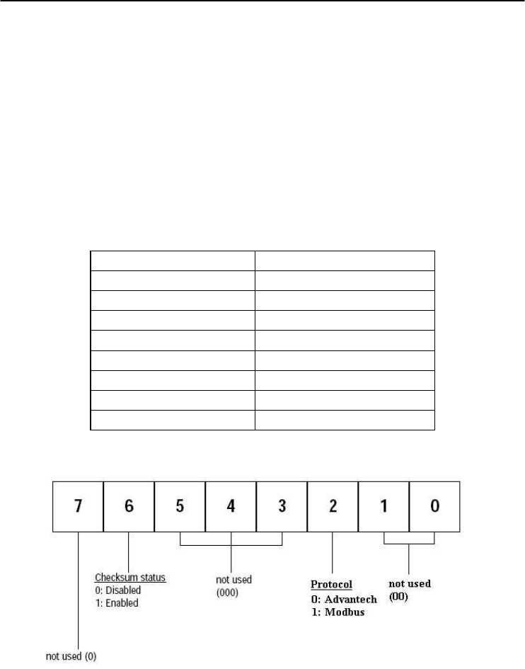
Chapter 7
7-
15
ADAM 4000 Series User’s Manual
$AA2
Example command: $452 (cr)
response: !45400600 (cr)
The command asks the digital I/O module at address 45h to
send its configuration data.
The digital I/O module at address 45h responds with baud
rate 9600, no checksum function and module supports for
Advantech protocol.
Table 7-2 Baud Rate Codes
Baud Rate Code (Hex)
Baud Rate
03 1200 bps
04 2400 bps
05 4800 bps
06 9600 bps
07 19.2 kbps
08 38.4 kbps
09 57.6 kbps
0A 115.2 kbps
Figure 7-2 Data format for FF (8-bit parameter)
4050, 4051, 4052, 4053, 4055,
4056S, 4056SO, 4060, 4068, 4069

Digital I/O and Relay Output
Counter/Frequency Command Set
7-
16
ADAM 4000 Series User’s Manual
$AA5
Name Reset Status command
Description Requests the Reset Status of the addressed digital I/O
module to see whether it has been reset since the last Reset
Status command.
Syntax $AA5(cr)
$ is a delimiter character.
AA (range 00-FF) represents the 2-character hexadecimal
address whose Reset Status is to be returned.
5 is the Reset Status command.
(cr) is the terminating character, carriage return (0Dh).
Response !AAS(cr) if the command was valid.
?AA(cr) if an invalid command has been issued.
There is no response if the module detects a syntax or
communication error, or even if the specified address does
not exist.
! is a delimiter character which indicates a valid command.
? is a delimiter character which indicates an invalid
command.
AA (range 00-FF) represents the 2-character hexadecimal
address which is to be calibrated.
S represents the Status bit that is returned by the digital I/O
module. If S=1, the module has been reset since it was
issued last time. If S=0, the module has not been reset since
the last Reset Status command was not issued.
(cr) is the terminating character, carriage return (0Dh).
4050, 4051, 4052, 4053, 4055,
4056S, 4056SO, 4060, 4068, 4069

Chapter 7
7-
17
ADAM 4000 Series User’s Manual
$AA5
Example command: $395(cr)
response: !390(cr)
The command tells the digital I/O module at address 39h to
return its Reset Status.
The digital I/O module at address 39h returns the value S=0.
This indicates that the digital I/O module has not been reset
or powered on since a Reset Status command was issued
last time.
4050, 4051, 4052, 4053, 4055,
4056S, 4056SO, 4060, 4068, 4069

Digital I/O and Relay Output
Counter/Frequency Command Set
7-
18
ADAM 4000 Series User’s Manual
$AAF
Name Read Firmware Version command
Description The command requests the digital I/O module at address
AA to return the version code of its firmware
Syntax $AAF (cr)
$ is a delimiter character.
AA (range 00-FF) represents the 2-character hexadecimal
address that you will access to.
F is the Read Firmware Version command.
(cr) is the terminating character, carriage return (ODh).
Response !AA(Version)(cr) if the command is valid.
There is no response if the module detects a syntax or
communication error, or even if the specified address does
not exist.
! is a delimiter character which indicates a valid command.
AA (range 00-FF) represents the 2-character hexadecimal
address of the module.
(Version) is the version code of the module’s firmware at
address AA.
(cr) is the terminating character, carriage return (ODh).
4050, 4051, 4052, 4053, 4055,
4056S, 4056SO, 4060, 4068, 4069

Chapter 7
7-
19
ADAM 4000 Series User’s Manual
$AAM
Name Read Module Name command
Description The command requests the digital I/O module at address
AA to return its name
Syntax $AAM (cr)
$ is a delimiter character.
AA (range 00-FF) represents the 2-character hexadecimal
address that you will access to.
M is the Read Module Name command.
(cr) is the terminating character, carriage return (ODh).
Response !AA(Module Name)(cr) if the command is valid.
There is no response if the module detects a syntax or
communication error, even or if the specified address does
not exist.
! is a delimiter character which indicates a valid command.
AA (range 00-FF) represents the 2-character hexadecimal
address of the module.
(Module Name) is the name of the module at address AA.
For example, 4052
(cr) is the terminating character, carriage return (ODh).
4050, 4051, 4052, 4053, 4055,
4056S, 4056SO, 4060, 4068, 4069

Digital I/O and Relay Output
Counter/Frequency Command Set
7-
20
ADAM 4000 Series User’s Manual
$AAX0TTTTDDDD
Name Write Safety Value command
Description Force the DO channels to safety status when communication
is in time-out and over pre-defined period.
Syntax $AAX0TTTTDDDD(cr)
$ is a delimiter character.
AA (range 00-FF) represents the 2-character hexadecimal
address that you will access to.
X0 is the Write Safety Value command.
TTTT is the time, 100 ms per number.
DDDD is the four-hexadecimal character representing the
desired input safety value. The first character D is always 0,
and the others are the channels values.
For Example, 017A
First character is always 0
The meaning of 17A is as follows:
Digital value 0 0 01011110 1 0
Adam-4056SO channel no. 11 10 9 8 7 6 5 4 3 2 1 0
17A means that the status of channel 1, 3, 4, 5, 6, 8 is ON;
and the rest are OFF.
(cr) is the terminating character, carriage return (0Dh).
Response >(cr) if the command was valid.
?AA(cr) if an invalid command has been issued.
There is no response if the module detects a syntax or
communication error, or even if the specified address does
not exist.
> is a delimiter character which indicates a valid command.
? is a delimiter character which indicates an invalid
command.
AA (range 00-FF) represents the responding 2-character
hexadecimal address of the module.
(cr) is the terminating character, carriage return (0Dh).
4055, 4056S, 4056SO,
4060, 4068, 4069

Chapter 7
7-
21
ADAM 4000 Series User’s Manual
$AAX1
Name Read Safety Value command
Description Read the time-out setting and pre-defined safety status of DO
channels.
Syntax $AAX1(cr)
$ is a delimiter character.
AA (range 00-FF) represents the 2-character hexadecimal
address that you will access to.
X1 is the Read Safety Value command.
(cr) is the terminating character, carriage return (0Dh).
Response ! TTTTDDDD(cr) if the command is valid.
?AA(cr) if an invalid command has been issued.
! is a delimiter character which indicates a valid command.
? is a delimiter character which indicates an invalid
command.
TTTT is the time, 100 ms per number.
DDDD is the four-hexadecimal character representing the
desired input safety value. The first character D is always 0,
and the others are the channels values.
For Example, 017A
First character is always 0
The meaning of 17A is as follows:
Digital value 0 0 01011110 1 0
Adam-4056SO channel no. 11 10 9 8 7 6 5 4 3 2 1 0
17A means channels 1, 3,4,5, 6, 8 are ON, and the rest are
OFF.
(cr) is the terminating character, carriage return (ODh).
4055, 4056S, 4056SO,
4060, 4068, 4069

Digital I/O and Relay Output
Counter/Frequency Command Set
7-
22
ADAM 4000 Series User’s Manual
$AAX2
Name Read Safety Flag command
Description Requests the Safety Flag of the addressed digital I/O module
to see whether the safety value has been executed since Write
Safety Value command was set.
Syntax $AAX2(cr)
$ is a delimiter character.
AA (range 00-FF) represents the 2-character hexadecimal
address that you will access to.
X2 is the Read Safety Flag command.
Response !XX (cr) if the command is valid.
XX is two-hexadecimal character – (00: OFF, 01: ON)
?AA(cr) if an invalid command has been issued.
! is a delimiter character which indicates a valid command.
? is a delimiter character which indicates an invalid
command.
(cr) is the terminating character, carriage return (ODh).
4055, 4056S, 4056SO,
4060, 4068, 4069

Chapter 7
7-
23
ADAM 4000 Series User’s Manual
$AAE0
Name Read and Clear over Current Status Flag command
Description Read the Over Current Status Flag and Clear the Flag
simultaneously.
Syntax $AAE0(cr)
$ is a delimiter character.
AA (range 00-FF) represents the 2-character hexadecimal
address that you will access to.
E0 is the Read and Clear over Current Status Flag command.
(cr) is the terminating character, carriage return (ODh).
Response !AAX(cr): if the command is valid.
?AA(cr): if an invalid command has been issued.
X is one-hexadecimal character (range from 0 to 7)
X=0: No over current occur
X=1: DO0~3 has over current occurred
X=2: DO4~7 has over current occurred
X=4: DO8~11 has over current occurred
! is a delimiter character which indicates a valid command
? is a delimiter character which indicates an invalid command
(cr) is the terminating character, carriage return (ODh).
4056SO

Digital I/O and Relay Output
Counter/Frequency Command Set
7-
24
ADAM 4000 Series User’s Manual
$AAP
Name Read the Low Power Status of Module command
Description The command requests the module at address AA to return
the low power status of module
Syntax $AAP(cr)
$ is a delimiter character.
AA (range 00-FF) represents the 2-character hexadecimal
address that you will access to.
P is the Read the Low Power Status of Module command.
(cr) is the terminating character, carriage return (ODh).
Response !AAS(cr) if the command was valid.
?AA(cr) if an invalid command has been issued.
There is no response if the module detects a syntax or
communication error, or even if the specified address does
not exist.
! is a delimiter character which indicates a valid command
? is a delimiter character which indicates an invalid command
AA (range 00-FF) represents the calibrated 2-character
hexadecimal address of the module.
S represents the Status bit from the low power status. When
the logic equals to 1, it represents low power. When it equals
to zero, it means normal.
(cr) is the terminating character, carriage return (0Dh).
4069

Chapter 7
7-
25
ADAM 4000 Series User’s Manual
$AAS
Name Change and Read the Low Power Mode of Module command
Description The command requests the module at address AA to change
and return the status of low power mode of module
Syntax $AAS(cr)
$ is a delimiter character.
AA (range 00-FF) represents the 2-character hexadecimal
address that you will access to.
S is the Change and Read the Low Power Mode of Module
command
(cr) is the terminating character, carriage return (ODh).
Response !AAX(cr) if the command was valid.
?AA(cr) if an invalid command has been issued.
There is no response if the module detects a syntax or
communication error, or even if the specified address does
not exist.
! is a delimiter character which indicates a valid command
? is a delimiter character which indicates an invalid command
AA (range 00-FF) represents the calibrated 2-character
hexadecimal address of the module.
X represents the Status bit from the low power status. When
the logic is 1, it represents low power. However, if the logic
is 0, it is normal
(cr) is the terminating character, carriage return (0Dh).
4069

Digital I/O and Relay Output
Counter/Frequency Command Set
7-
26
ADAM 4000 Series User’s Manual
$AAXnnnn
Name Watchdog Timer Setting command
Description This command set the communication watchdog timer
(WDT) cycle time.
Syntax $AAXnnnn(cr)
$ is a delimiter character.
AA (range 00-FF) represents the 2-character hexadecimal
address of the analog input module which is to be read.
X is Watchdog Timer Setting command.
nnnn (range 0000~9999) represents the specified value of
communication cycle you want to set. (Unit: 0.1 second)
(cr) is the terminating character, carriage return (0Dh).
Response !AA(cr) if the command was valid.
?AA(cr) if an invalid operation was entered.
There is no response if the module detects a syntax error or
communication error or if the specified address does not
exist.
! delimiter character indicates a valid command was
received.
? delimiter character indicates the command was invalid.
AA (range 00-FF) represents the 2-character hexadecimal
address of the analog input module.
(cr) represents terminating character, carriage return (0Dh).
Example command: $02X1234(cr)
response: !02(cr)
The command set the WDT cycle as 1234 in the input
module at address 02.
NOTICE: If the value of “nnnn” is 0000, the communication WDT
function will be disable.
4052, 4055, 4056S,
4056SO, 4068, 4069

Chapter 7
7-
27
ADAM 4000 Series User’s Manual
$AAY
Name Read Communication Watchdog Timer Cycle Setting
command
Description This command read the setting of communication watchdog
timer (WDT) cycle time.
Syntax $AAY(cr)
$ is a delimiter character.
AA (range 00-FF) represents the 2-character hexadecimal
address of the analog input module which is to be read.
Y is the Read Communication Watchdog Timer Cycle
Setting command.
(cr) is the terminating character, carriage return (0Dh).
Response !AAnnnn(cr) if the command was valid.
?AA(cr) if an invalid operation was entered.
There is no response if the module detects a syntax error or
communication error or if the specified address does not
exist.
! delimiter character indicates a valid command was
received.
? delimiter character indicates the command was invalid.
AA (range 00-FF) represents the 2-character hexadecimal
address of the analog input module.
nnnn (range 0000~9999) represent the specified value of
communication cycle you read. (Unit: 0.1 second)
(cr) represents terminating character, carriage return (0Dh).
Example command: $02Y(cr)
response: !020030(cr)
The command read the WDT cycle as 0030 in the input
module at address 02.
4052, 4055, 4056S,
4056SO, 4068, 4069

Digital I/O and Relay Output
Counter/Frequency Command Set
7-
28
ADAM 4000 Series User’s Manual
7.2 Counter/Frequency Module Command
7.2.1 Configuration, Counter Input and Display Command Set
Command
S
y
ntax Description I/O Module
%AANNTTCCFF
Sets the address, input mode, baud rate, checksum
status and/or frequency gate time for a specified
counter/frequenc
y
module
4080,
4080D
$AA2 Requests the return of the configuration data from the
counter/frequency module 4080,
4080D
$AAF Requests the counter/frequency module to return the
version code of its firmware
4080,
4080D
$AAM Requests the counter/frequency module to return its
name 4080,
4080D
$AABS Set the input signal mode of the specified
counter/frequency module to either non-isolated
(TTL) or photo-isolated.
4080,
4080D
$AAB Read the input mode of the specified
counter/frequenc
y
module.
4080,
4080D
#AAN Instructs the addressed counter/ frequency module to
read the counter or frequency value of counter 0 or
counter 1 and return the acquired data.
4080,
4080D
$AA8V Select whether LED will display data from the
counter/frequency module directly or from the host
computer.
4080D
$AA8 Read the LED Data Origin status which determines
whether LED will display data from the counter/
frequenc
y
module directl
y
or from the host computer
4080D
$AA9(data) The host computer sends data to the addressed
module to display on its LED. This command is valid
only after selectting to display host computer data
(
$A
A
8V
)
4080D
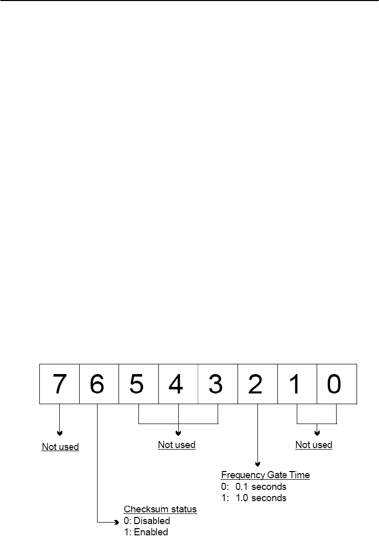
Chapter 7
7-
29
ADAM 4000 Series User’s Manual
%AANNTTCCFF
Name Configuration command
Description Sets the address, input mode, baud rate, checksum status
and frequency gate time for a specified counter/frequency
module
Syntax %AANNTTCCFF (cr)
% is a delimiter character.
AA (range 00-FF) represents the 2-character hexadecimal
address that you will access to.
NN represents the new hexadecimal address of the
counter/frequency module. Range is from 00h to FFh.
TT represents the input mode.
50h : counter input mode
51h : frequency measurement mode
CC represents the baud rate code.
(Refer to Table 7-3 on next page).
Hexadecimal value FF which is converted to an 8-bit
parameter represents the checksum status and frequency
gate time. The layout of the 8-bit parameter is shown in
Figure 7-3 below.
Bits 0, 1, 3, 4, 5 and 7 are not used and are set to 0.
(cr) is the terminating character, carriage return (0Dh).
Figure 7-3 Data format for FF (8-bit parameter)
4080, 4080D

Digital I/O and Relay Output
Counter/Frequency Command Set
7-
30
ADAM 4000 Series User’s Manual
%AANNTTCCFF
Response !AA(cr) if the command is valid.
?AA(cr) if an invalid parameter was entered or the INIT*
terminal was not grounded when changing baud rate or
checksum setting were attempted.
There is no response if the module detects a syntax or
communication error, or even if the specified address does
not exist.
! is a delimiter character which indicates a valid command.
? is a delimiter character which indicates an invalid
command.
AA (range 00-FF) represents the 2-character hexadecimal
address of the module.
(cr) is the terminating character, carriage return (0Dh).
Example command: %0120510600(cr)
response: !20(cr)
The ADAM 4080D module is configured by changing
address 01 to a new address 20, choosing frequency
measurement module, assigning 9600 to baud rate, setting
frequency gate time 0.1 second and no checksum checking
or generation.
The response indicates that the command was received.
Wait seven seconds to let the new configuration settings
take effect before you issue a new command to the module.
Table 4-7 Baud Rate Codes
Baud Rate Code (Hex) Baud Rate
03 1200 bps
04 2400 bps
05 4800 bps
06 9600 bps
07 19.2 Kbps
08 38.4 Kbps
NOTICE: You can change all configuration parameters dynamically
except checksum and baud rate parameters. They can only be
altered when the INIT* terminal is grounded.
4080, 4080D

Chapter 7
7-
31
ADAM 4000 Series User’s Manual
$AA2
Name Configuration Status command
Description The command requests the return of the configuration data
from the counter/frequency module at address AA.
Syntax $AA2(cr)
$ is a delimiter character.
AA (range 00-FF) represents the 2-character hexadecimal
address that you will access to.
2 is the Configuration Status command.
(cr) is the terminating character, carriage return (0Dh).
Response !AATTCCFF (cr) if the command is valid.
?AA(cr) if an invalid operation was entered
There is no response if the module detects a syntax or
communication error, or even if the specified address does
not exist.
! is a delimiter character which indicates a valid command.
? is a delimiter character which indicates an invalid
command.
AA (range 00-FF) represents the 2-character hexadecimal
that you will access to.
TT (50h or 51h) represents the type of code. 50h means
using module as a counter. 51h means using module as a
frequency measurement module.
CC represents the baud rate code.
Hexadecimal value FF which also equals to an 8-bit
parameter represents the checksum status and frequency
gate time. The layout of the 8-bit parameter is shown in
figure 4-5. The bits are not used and are set to 0.
(cr) is the terminating character, carriage return (0Dh)
(Also see the %AANNTTCCFF configuration command)
4080, 4080D

Digital I/O and Relay Output
Counter/Frequency Command Set
7-
32
ADAM 4000 Series User’s Manual
$AAF
Name Read Version command
Description The command requests the analog input module at address
AA to return the version code of its firmware.
Syntax $AAF (cr)
$ is a delimiter character.
AA (range 00-FF) represents the 2-character hexadecimal
address that you will access to.
F is the Read Version command.
(cr) is the terminating character, carriage return (0Dh).
Response !AA(Version)(cr) if the command is valid.
There is no response if the module detects a syntax or
communication error, or even if the specified address does
not exist.
! is a delimiter character which indicates a valid command.
AA (range 00-FF) represents the 2-character hexadecimal
address of the module.
(Version) is the version code of the module's firmware at
address AA.
(cr) is the terminating character, carriage return (0Dh).
4080, 4080D

Chapter 7
7-
33
ADAM 4000 Series User’s Manual
$AAM
Name Read Module Name command
Description The command requests the counter/frequency module at
address AA to return its name
Syntax $AAM (cr)
$ is a delimiter character.
AA (range 00-FF) represents the 2-character hexadecimal
address that you will access to.
M is the Read Module Name command.
(cr) is the terminating character, carriage return (0Dh).
Response !AA(Module Name)(cr) if the command is valid.
There is no response if the module detects a syntax or
communication error, or even if the specified address does
not exist.
! is a delimiter character which indicates a valid command.
AA (range 00-FF) represents the 2-character hexadecimal
address of the module.
(Module Name) is the name of the module at address AA.
For example, 4080D
(cr) is the terminating character, carriage return (0Dh).
4080, 4080D

Digital I/O and Relay Output
Counter/Frequency Command Set
7-
34
ADAM 4000 Series User’s Manual
$AABS
Name Set Input Mode command
Description Set the input signal mode of the specified counter/
frequency module to either non-isolated (TTL) or
photo-isolated.
Syntax $AABS(cr)
$ is a delimiter character.
AA (range 00-FF) represents the 2-character hexadecimal
address that you will access to.
B is the Set Input Signal Mode command.
S indicates the input signal mode. When S = 0, the module
is configured to non-isolated (TTL) input. If S = 1, the
module is configured to photo-isolated input.
(cr) is the terminating character, carriage return (0Dh).
Response !AA(cr) if the command is valid.
There is no response if the module detects a syntax or
communication error, or even if the specified address does
not exist.
! is a delimiter character which indicates a valid command.
AA (range 00-FF) represents the 2-character hexadecimal
address of the module.
(cr) is the terminating character, carriage return (0Dh).
Example command: $03B0(cr)
response: !03(cr)
The command configures the counter/frequency modules at
address 03 to retrieve a non-isolated input. The module
replies by sending its address to indicate that the command
was executed.
NOTICE: The input mode command is not related to a specific channel.
When the input mode is set both channels are changed
accordingly.
4080, 4080D

Chapter 7
7-
35
ADAM 4000 Series User’s Manual
$AAB
Name Read Input Mode command
Description Read the input mode of the specified counter/frequency
module.
Syntax $AAB(cr)
$ is a delimiter character.
AA (range 00-FF) represents the 2-character hexadecimal
address that you will access to.
B is the Read Input Mode command.
(cr) is the terminating character, carriage return (0Dh).
Response !AAS(cr) if the command is valid.
There is no response if the module detects a syntax or
communication error, or even if the specified address does
not exist.
! is a delimiter character which indicates a valid command.
AA (range 00-FF) represents the 2-character hexadecimal
address of the module.
S indicates the input signal mode. When S = 0, the module
is configured to non-isolated (TTL) input. If S = 1, the
module is configured to photo-isolated input.
(cr) is the terminating character, carriage return (0Dh).
Example command: $03B(cr)
response: !030(cr)
The command requests the counter/frequency module at
address 03 to return its input mode. The module replies by
setting the input mode to retrieve non-isolated input.
4080, 4080D

Digital I/O and Relay Output
Counter/Frequency Command Set
7-
36
ADAM 4000 Series User’s Manual
#AAN
Name Read Counter or Frequency Value command
Description Instructs the addressed counter/frequency module at
address AA to read the counter or frequency value of
counter 0 or counter 1 and return the acquired data.
Syntax #AAN(cr)
# is a delimiter character.
AA (range 00-FF) represents the 2-character hexadecimal
address that you will access to.
N represents the counter number.
N=0 represents counter 0
N=1 represents counter 1
(cr) is the terminating character, carriage return (0Dh).
Response >data(cr) if the command is valid.
?AA(cr) if an invalid operation was entered.
There is no response if the module detects a syntax or
communication error, or even if the specified address does
not exist.
? is a delimiter character which indicates an invalid
command.
AA (range 00-FF) represents the 2-character hexadecimal
address of the module.
(data) is the value that is retrieved by the module from
reading counter 0 or counter 1. The data format consists of
eight hexadecimal characters.
(cr) is the terminating character, carriage return (0Dh).
Example command: #120(cr)
response: >000002FE(cr)
The command requests the counter/frequency module at
address 12 to read the counter 0 and return the data. The
counter/frequency module at address 12 responds with
value 000002FE (hexadecimal) of counter 0 which is also
equivalent to 766 (decimal).
4080, 4080D

Chapter 7
7-
37
ADAM 4000 Series User’s Manual
$AA8V
Name Select LED Data Origin command
Description Select whether LED will display data from either the host
computer or the counter/frequency module directly.
Syntax $AA8V(cr)
$ is a delimiter character.
AA (range 00-FF) represents the 2-character hexadecimal
address that you will access to.
8 is the Select LED Data Origin command.
V indicates the origin of the data which is to be displayed
on the LED:
V=0 sets the LED data origin to the module's counter 0
V=1 sets the LED data origin to the module's counter 1
V=2 sets the LED data origin to the host computer
(cr) is the terminating character, carriage return (0Dh)
Response !AA(cr) if the command is valid.
?AA(cr) if an invalid operation was entered.
There is no response if the module detects a syntax or
communication error, or even if the specified address does
not exist.
! is a delimiter character which indicates a valid command.
? is a delimiter character which indicates an invalid
command.
AA (range 00-FF) represents the 2-character hexadecimal
address of the module.
(cr) is the terminating character, carriage return (0Dh).
Example command: $0182(cr)
response: !01(cr)
The command sets the counter/frequency modules at
address 01 to display data sent by the host computer. After
this command has been issued, the host computer can use
command $AA9(data) to send the data to the module.
4080D

Digital I/O and Relay Output
Counter/Frequency Command Set
7-
38
ADAM 4000 Series User’s Manual
$AA8
Name Read LED Data Origin command
Description Read the LED Data Origin status which determines whether
LED will display data from either the host computer or the
counter/frequency module directly.
Syntax $AA8(cr)
$ is a delimiter character.
AA (range 00-FF) represents the 2-character hexadecimal
address that you will access to.
8 is the Read LED Data Origin command.
(cr) is the terminating character, carriage return (0Dh)
Response !AAV(cr) if the command is valid.
?AA(cr) if an invalid operation was entered.
There is no response if the module detects a syntax or
communication error, or even if the specified address does
not exist.
! is a delimiter character which indicates a valid command.
? is a delimiter character which indicates an invalid
command.
AA (range 00-FF) represents the 2-character hexadecimal
address of the module.
V indicates the origin of the data to be displayed on the
LED:
V=0 sets the LED data origin to the module's counter 0
V=1 sets the LED data origin to the module's counter 1
V=2 sets the LED data origin to the host computer
(cr) is the terminating character, carriage return (0Dh).
Example command: $018(cr)
response: !011(cr)
The command requests the counter/frequency module at
address 01 to return its LED Data Origin status. The
module replies that it currently displays data from counter
1.
4080D

Chapter 7
7-
39
ADAM 4000 Series User’s Manual
$AA9(data)
Name Send Data to LED command
Description The host computer sends data to the addressed module to
display on its LED.
Syntax $AA9(data)(cr)
$ is a delimiter character.
AA (range 00-FF) represents the 2-character hexadecimal
address that you will access to.
9 is the Send LED Data command.
(data) is a floating point numeral consisting of five digits,
and there can be a decimal point. Its maximum value is
99999.
(cr) is the terminating character, carriage return (0Dh)
Response !AA(cr) if the command is valid.
?AA(cr) if an invalid operation was entered.
There is no response if the module detects a syntax or
communication error, or even if the specified address does
not exist.
! is a delimiter character which indicates a valid command.
? is a delimiter character which indicates an invalid
command.
AA (range 00-FF) represents the 2-character hexadecimal
address of a counter/frequency module.
(cr) is the terminating character, carriage return (0Dh).
Example command: $0198999.9(cr)
response: !01(cr)
The command requests the host computer to send 8999.9 to
the counter/frequency module at address 01 for LED
display. This command is only valid after the command
$0182 has been issued.
4080D

Digital I/O and Relay Output
Counter/Frequency Command Set
7-
40
ADAM 4000 Series User’s Manual
7.2.2 Counter Setup Command Set
Command
Syntax Command Name Description I/O Module
$AAAG Set Gate Mode Requests the specified counter/
frequency module to set its gate
mode to either high, low or
disabled
4080, 4080D
$AAA Read Gate Mode Requests the specified counter/
frequency module to return the
status of its gate mode
4080, 4080D
$AA3N(data) Set Maximum
Counter Value Sets the maximum value of
counter 0 or counter 1 for the
specified counter/frequency
module
4080, 4080D
$AA3N Read Maximum
Counter Value Reads the maximum value of
counter 0 or counter 1 of the
specified counte/ frequency
module
4080, 4080D
$AA5NS Start/Stop Counter The command orders the specified
counter/frequency module to start
or stop counting
4080, 4080D
$AA5N Read Counter
Start/Stop Status The addressed counter frequency
module returns its status indicating
whether counting is enabled or
diabled
4080, 4080D
$AA6N Clear Counter The command clears the counter 0
or counter 1 of the specified
counter module
4080, 4080D
$AA7N Read Overflow Flag The addressed module returns the
status of the overflow flag of
counter 0 or counter 1
4080, 4080D

Chapter 7
7-
41
ADAM 4000 Series User’s Manual
$AAAG
Name Set Gate Mode command
Description Request the specified counter/frequency module to set its
gate to one of the three states, high, low or disabled.
Syntax $AAAG(cr)
$ is a delimiter character.
AA (range 00-FF) represents the 2-character hexadecimal
address that you will access to.
A is the Gate Mode command.
G determines the gate mode:
G = 0 the gate is low
G = 1 the gate is high
G = 2 the gate is disabled
(cr) is the terminating character, carriage return (0Dh).
Response !AA(cr) if the command is valid.
There is no response if the module detects a syntax or
communication error, or even if the specified address does
not exist.
! is a delimiter character which indicates a valid command.
AA (range 00-FF) represents the 2-character hexadecimal
address of the module.
(cr) is the terminating character, carriage return (0Dh).
Example command: $01A1(cr)
response: !01(cr)
The command requests the counter/frequency module at
address 01 to set its gate high. The module will reply with
an address indicating that it has executed the command.
4080, 4080D

Digital I/O and Relay Output
Counter/Frequency Command Set
7-
42
ADAM 4000 Series User’s Manual
$AAA
Name Read Gate Mode command
Description Request the specified counter/frequency module to return
its gate status.
Syntax $AAA(cr)
$ is a delimiter character.
AA (range 00-FF) represents the 2-character hexadecimal
address that you will access to.
A is the Read Gate Mode command.
(cr) is the terminating character, carriage return (0Dh).
Response !AAG(cr) if the command is valid.
There is no response if the module detects a syntax or
communication error, or even if the specified address does
not exist.
! is a delimiter character which indicates a valid command.
AA (range 00-FF) represents the 2-character hexadecimal
address of the module.
G determines the gate mode.
G = 0 the gate is low
G = 1 the gate is high
G = 2 the gate is disabled.
(cr) is the terminating character, carriage return (0Dh).
Example command: $01A(cr)
response: !011(cr)
The command requests the counter/frequency module to
return its gate status. The module at address 01 replies with
gate setting high.
4080, 4080D

Chapter 7
7-
43
ADAM 4000 Series User’s Manual
$AA3N(data)
Name Set Maximum Counter Value command
Description Set the maximum value for either counter 0 or counter 1 of
a specified counter/frequency module.
Syntax $AA3N(data)(cr)
$ is a delimiter character.
AA (range 00-FF) represents the 2-character hexadecimal
address that you will access to.
3 is the Set Maximum Counter Value command.
N determines the counter for which the maximum counter
value is to be set.
N = 0 represents counter 0
N = 1 represents counter 1
(data) is the maximum count value which consists of eight
hexadecimal digits. The module will accumulate the input
counts until it reaches the maximum value. When the count
exceeds the maximum counter value, the counter will stop
counting. The programmer should use the command
$AA6N to reset the counter to 1.
(cr) is the terminating character, carriage return (0Dh).
Response !AA(cr) if the command is valid.
?AA(cr) if an invalid operation was entered.
There is no response if the module detects a syntax or
communication error, or even if the specified address does
not exist.
! is a delimiter character which indicates a valid command.
? is a delimiter character which indicates an invalid
command.
AA (range 00-FF) represents the 2-character hexadecimal
address of the module.
(cr) is the terminating character, carriage return (0Dh).
Example command: $24300000ffff(cr)
response: !24(cr)
The command requests the counter/frequency module at
address 24 to set the maximum value for counter 0 to 65535
(0x0000ffff). The module will reply that it has executed the
command.
4080, 4080D

Digital I/O and Relay Output
Counter/Frequency Command Set
7-
44
ADAM 4000 Series User’s Manual
$AA3N
Name Read Maximum Counter Value command
Description Read the maximum value of counter 0 or counter 1 for a
specified counter/frequency module.
Syntax $AA3N(cr)
$ is a delimiter character.
AA (range 00-FF) represents the 2-character hexadecimal
address that you will access to.
3 is the Read Maximum Counter Value command.
N determines the counter for which the maximum counter
value is to be set.
N = 0 represents counter 0
N = 1 represents counter 1
(cr) is the terminating character, carriage return (0Dh).
Response !AA(data)(cr) if the command is valid.
?AA(cr) if an invalid operation was entered.
There is no response if the module detects a syntax or
communication error, or even if the specified address does
not exist.
! is a delimiter character which indicates a valid command.
? is a delimiter character which indicates an invalid
command. AA (range 00-FF) represents the 2-character
hexadecimal address of the module.
(data) is the maximum counter value which consists of
eight hexadecimal digitals.
(cr) is the terminating character, carriage return (0Dh).
Example command: $2430(cr)
response: !240000ffff(cr)
The command requests the counter/frequency module at
address 24 for the maximum number of counter 0. The
module replies the maximum count number of channel 0
with 65535 (0000ffff)
4080, 4080D

Chapter 7
7-
45
ADAM 4000 Series User’s Manual
$AA5NS
Name Start/Stop Counter command
Description Request the counter/frequency module to start or stop the
counting for either counter 0 or counter 1.
Syntax $AA5NS(cr)
$ is a delimiter character.
AA (range 00-FF) represents the 2-character hexadecimal
address that you will access to.
5 is the Start/Stop Counter command.
N determines the counter that should be either enabled or
disabled.
N = 0 represents counter 0
N = 1 represents counter 1
S represents the counter status.
S = 0 stops counting
S = 1 starts counting
(cr) is the terminating character, carriage return (0Dh).
Response !AA(cr) if the command is valid. There is no response if
the module detects a syntax or communication error, or
even if the specified address does not exist.
! is a delimiter character which indicates a valid command.
AA (range 00-FF) represents the 2-character hexadecimal
address of a counter input module.
(cr) is the terminating character, carriage return (0Dh).
Example command: $06501(cr)
response: !06(cr)
The command requests the counter 0 of counter/frequency
module at address 06 to start. The addressed module replies
with its address indicating that the command has been
executed. Counter 0 has started.
4080, 4080D

Digital I/O and Relay Output
Counter/Frequency Command Set
7-
46
ADAM 4000 Series User’s Manual
$AA5N
Name Read Counter Start/Stop Status command
Description Requests the addressed counter/frequency module to
indicate whether counter 0 or counter 1 is active.
Syntax $AA5N(cr)
$ is a delimiter character.
AA (range 00-FF) represents the 2-character hexadecimal
address that you will access to.
5 is the Read Counter Start/Stop Status command.
N determines the counter for which the status should be
returned.
N = 0 represents counter 0
N = 1 represents counter 1
(cr) is the terminating character, carriage return (0Dh).
Response !AAS(cr) if the command is valid.
There is no response if the module detects a syntax or
communication error, or even if the specified address does
not exist.
! is a delimiter character which indicates a valid command.
AA (range 00-FF) represents the 2-character hexadecimal
address of the module.
S represents the counter status.
S = 1 indicates the status is counting
S = 0 indicates the status is not counting
(cr) is the terminating character, carriage return (0Dh).
Example command: $0650(cr)
response: !061(cr)
The command requests the counter/frequency module at
address 06 to return the status of counter 0. The module
replies that the counter 0 is in the counting process.
4080, 4080D

Chapter 7
7-
47
ADAM 4000 Series User’s Manual
$AA6N
Name Clear Counter command
Description Clears the counter 0 or counter 1 of the specified
counter/frequency module.
Syntax $AA6N(cr)
$ is a delimiter character.
AA (range 00-FF) represents the 2-character hexadecimal
address that you will access to.
6 is the Clear Counter command.
N determines the counter which should be cleared.
N = 0 represents counter 0
N = 1 represents counter 1
(cr) is the terminating character, carriage return (0Dh).
Response !AA(cr) if the command is valid.
There is no response if the module detects a syntax or
communication error, or even if the specified address does
not exist.
! is a delimiter character which indicates a valid command.
AA (range 00-FF) represents the 2-character hexadecimal
address of the module.
(cr) is the terminating character, carriage return (0Dh).
Example command: $1361(cr)
response: !13(cr)
The command requests the counter/frequency module at
address 13 to clear counter 1. The module replies with its
address indicating that the counter has been cleared.
4080, 4080D

Digital I/O and Relay Output
Counter/Frequency Command Set
7-
48
ADAM 4000 Series User’s Manual
$AA7N
Name Read/Clear Overflow Flag command
Description The command requests the module to return the status of
the overflow flag for either counter 0 or counter 1. Then
clear the flag afterwards.
Syntax $AA7N(cr)
$ is a delimiter character.
AA (range 00-FF) represents the 2-character hexadecimal
address that you will access to.
7 is the Read/Clear Overflow Flag command.
N determines the channel whose overflow flag status
should be read and cleared. When N = 0, it represents
counter 0. On the other hand, N = 1 represents counter 1
(cr) is the terminating character, carriage return (0Dh).
Response !AAV(cr) if the command is valid.
?AA(cr) if an invalid operation was entered.
There is no response if the module detects a syntax or
communication error, or even if the specified address does
not exist.
! is a delimiter character which indicates a valid command.
? is a delimiter character which indicates an invalid
command .
AA (range 00-FF) represents the 2-character hexadecimal
address of the module.
V represents the status of the Nth channel's overflow flag.
V = 1 means that the overflow flag has been set because the
counting has exceeded the maximum count.
V = 0 means that the overflow flag has not been set.
(cr) is the terminating character, carriage return (0Dh).
Example command: $1371(cr)
response: !131(cr)
The command requests the counter/frequency module at
address 13 to return the status of the overflow flag for
counter 1 and to reset it. The module replies with the
overflow flag for counter 1indicating overflow. Then it is
being reset.
4080, 4080D

Chapter 7
7-
49
ADAM 4000 Series User’s Manual
7.2.3 Digital Filter and Programmable Threshold Command Set
Command Syntax
Command Name Description I/O Module
$AA4S Enable/Disable
Digital Filter Enables or disables the digital
filter of the addressed
counter/frequenc
y
module
4080,
4080D
$AA4 Read Filter Status The addressed counter
frequency module returns the
status of its digital filter
4080,
4080D
$AA0H(data) Set Minimum
Input Signal Width
at High Level
Sets the minimum input signal
width at high level for a
specified counter/frequency
module
4080,
4080D
$AA0H Read Minimum
Input Signal Width
at High Level
Reads the minimum input signal
width setting at high level for a
specified counter/frequency
module
4080,
4080D
$AA0L(data) Set Minimum
Input Signal Width
at Low Level
Sets the minimum input signal
width at low level for a specified
counter/frequency module
4080,
4080D
$AA0L Read Minimum
Input Signal Width
at Low Level
Reads minimum input signal
width setting at low level for a
specified counter/frequency
module
4080,
4080D
$AA1H(data) Set Non-isolated
High Trigger Level Sets the high trigger level of
non-solated input signals for a
specified counter/frequency
module
4080D
$AA1H Read Non-isolated
High Trigger Level Requests the addressed counter
requency module to return the
high trigger level for non-isolated
input si
g
nals
4080D
$AA1L(data) Set Non-isolated
Low Trigger Level Sets the low trigger level of
non-solated input signals for a
specified counter/frequency
module
4080D
$AA1L Read Non-isolated
Low Trigger Level Requests the addressed ounter/
frequency module to return the
low trigger level for non-isolated
input signals
4080D

Digital I/O and Relay Output
Counter/Frequency Command Set
7-
50
ADAM 4000 Series User’s Manual
$AA4S
Name Enable/Disable Digital Filter command
Description Enables or disables the digital filter of the counter/
frequency module.
Syntax $AA4S(cr)
$ is a delimiter character.
AA (range 00-FF) represents the 2-character hexadecimal
address that you will access to.
4 is the Enable/Disable Filter command.
S is the digital filter mode.
S = 0 means disable filter
S = 1 means enable filter
(cr) is the terminating character, carriage return (0Dh).
Response !AA(cr) if the command is valid.
There is no response if the module detects a syntax or
communication error, or even if the specified address does
not exist.
! is a delimiter character which indicates a valid command.
AA (range 00-FF) represents the 2-character hexadecimal
address of the module.
(cr) is the terminating character, carriage return (0Dh).
Example command: $0340(cr)
response: !03(cr)
The command orders the counter/frequency module at
address 03 to disable its digital filter. The module returns
its address indicating that it has executed the command
successfully.
4080, 4080D

Chapter 7
7-
51
ADAM 4000 Series User’s Manual
$AA4
Name Read Filter Status command
Description Read the digital filter status of the addressed counter/
frequency module.
Syntax $AA4(cr)
$ is a delimiter character.
AA (range 00-FF) represents the 2-character hexadecimal
address that you will access to.
4 is the Read Filter Status command.
(cr) is the terminating character, carriage return (0Dh).
Response !AAS(cr) if the command is valid.
There is no response if the module detects a syntax or
communication error, or even if the specified address does
not exist.
! is a delimiter character which indicates an invalid
command.
AA (range 00-FF) represents the 2-character hexadecimal
address of the module.
S is the digital filter mode.
S = 0 means filter is disabled
S = 1 means filter is enabled
(cr) is the terminating character, carriage return (0Dh).
Example command: $034(cr)
response: !030(cr)
The command requests the counter/frequency module at
address 03 to return whether its digital filter is ON or not.
The module returns its address which indicates that its
digital filter is disabled.
4080, 4080D

Digital I/O and Relay Output
Counter/Frequency Command Set
7-
52
ADAM 4000 Series User’s Manual
$AA0H(data)
Name Set Minimum Input Signal Width at High Level command
Description Set the minimum input signal width at high level for a
specified counter/frequency module to filter the noise.
Syntax $AA0H(data)(cr)
$ is a delimiter character.
AA (range 00-FF) represents the 2-character hexadecimal
address that you will access to.
0H is the Set Minimum Input Signal Width at High Level
command.
(data) is the minimum width at high level. The unit is in
µsec (microseconds) and its resolution is 1 μsec. The
format is a five digit integer that can range from 2 μsec to
65535 μsec. Out of range values will cause errors.
(cr) is the terminating character, carriage return (0Dh).
Response !AA(cr) if the command is valid. The addressed module
stores the value and will recognize the input signal “high”
only after the input signal continues “high” and for longer
than the specified value.
?AA(cr) if an invalid operation was entered.
There is no response if the module detects a syntax or
communication error, or even if the specified address does
not exist.
! is a delimiter character which indicates a valid command.
? is a delimiter character which indicates an invalid
command.
AA (range 00-FF) represents the 2-character hexadecimal
address of the module.
(cr) is the terminating character, carriage return (0Dh).
Example command: $130H00020(cr)
response: !13(cr)
The command requests the counter/frequency module at
address 13 to set the minimum input width at high level to
20 μsec. The module stores the value and will identify an
input signal to be "high” only if the signal continues to be
“high” longer than 20 μsec. This function can be used as a
digital filter.
4080, 4080D

Chapter 7
7-
53
ADAM 4000 Series User’s Manual
$AA0H
Name Read Minimum Input Signal Width at High Level
command
Description Read the minimum input signal width at high level for a
specified counter/frequency module.
Syntax $AA0H(cr)
$ is a delimiter character.
AA (range 00-FF) represents the 2-character hexadecimal
address that you will access to.
0H is the Read Minimum Input Signal Width at High Level
command.
(cr) is the terminating character, carriage return (0Dh).
Response !AA(data)(cr) if the command is valid.
?AA(cr) if an invalid operation was entered.
There is no response if the module detects a syntax or
communication error, or even if the specified address does
not exist.
! is a delimiter character which indicates a valid command.
? is a delimiter character which indicates an invalid
command.
AA (range 00-FF) represents the 2-character hexadecimal
address of the module.
(data) is the minimum width at high level. The unit is in
μsec (microseconds) and its resolution is 1 μsec. The
format is a five digit integer that ranges from 2 μsec to
65535 μsec.
(cr) is the terminating character, carriage return (0Dh).
Example command: $130H(cr)
response: !1300020(cr)
The command requests the counter/frequency module at
address 13 to read its minimum input signal width at high
level. The module replies that its minimum input signal
width at high level is 20 μsec.
4080, 4080D

Digital I/O and Relay Output
Counter/Frequency Command Set
7-
54
ADAM 4000 Series User’s Manual
$AA0L(data)
Name Set Minimum Input Signal Width at Low Level command
Description Set the minimum input signal width at low level for a
specified counter/frequency module to filter noise.
Syntax $AA0L(data)(cr)
$ is a delimiter character.
AA (range 00-FF) represents the 2-character hexadecimal
address that you will access to.
0L is the Set Minimum Input Signal Width at Low Level
command.
(data) is the minimum width at low level. The unit is in
μsec (microseconds) and its resolution is 1 μsec. The
format is a five digit integer that can range from 2 μsec to
65535 μsec. Out of range values will cause errors.
(cr) is the terminating character, carriage return (0Dh).
Response !AA(cr) if the command is valid. The addressed module
stores the value and will identify the input signal “low”
only if the input signal continues to be “low” longer than
the specified time.
?AA(cr) if an invalid operation was entered.
There is no response if the module detects a syntax or
communication error, or even if the specified address does
not exist.
! is a delimiter character which indicates a valid command.
? is a delimiter character which indicates an invalid
command.
AA (range 00-FF) represents the 2-character hexadecimal
address of the module.
(cr) is the terminating character, carriage return (0Dh).
Example command: $050L00084(cr)
response: !05(cr)
The command requests the counter/frequency module at
address 05 to set the minimum input width at low level to
84 μsec. The module stores the value and will identify an
input signal to be "low” only if the signal continues to be
“low” longer than 84 μsec. This function can be used as
digital filter.
4080, 4080D

Chapter 7
7-
55
ADAM 4000 Series User’s Manual
$AA0L
Name Read Minimum Input Signal Width at Low Level command
Description Read the minimum input signal width at low level for a
specified counter/frequency module to filter noise.
Syntax $AA0L(cr)
$ is a delimiter character.
AA (range 00-FF) represents the 2-character hexadecimal
address that you will access to.
0L is the Read Minimum Input Signal Width at Low Level
command.
(cr) is the terminating character, carriage return (0Dh).
Response !AA(data)(cr) if the command is valid.
?AA(cr) if an invalid operation was entered.
There is no response if the module detects a syntax or
communication error, or even if the specified address does
not exist.
! is a delimiter character which indicates a valid command.
? is a delimiter character which indicates an invalid
command.
AA (range 00-FF) represents the 2-character hexadecimal
address of the module.
(data) is the minimum width at low level. The unit is in
μsec (microsecond) and its resolution is 1 μsec. The format
is a five digit integer that ranges from 2 μsec to 65535 μsec.
(cr) is the terminating character, carriage return (0Dh).
Example command: $050L(cr)
response: !0500084(cr)
The command requests the counter/frequency module at
address 05 to read its minimum input signal width at low
level. The module replies that its minimum input signal
width at low level is 84 μsec.
4080, 4080D

Digital I/O and Relay Output
Counter/Frequency Command Set
7-
56
ADAM 4000 Series User’s Manual
$AA1H(data)
Name Set Non-isolated High Trigger Level command
Description Set the high trigger level for non-isolated input signals for a
specified counter/frequency module.
Syntax $AA1H(data)(cr)
$ is a delimiter character.
AA (range 00-FF) represents the 2-character hexadecimal
address that you will access to.
1H is the Set Non-isolated High Trigger Level command.
(data) is the high trigger level for non-isolated input
The unit and resolution are both 0.1 V (voltage). The
format is a two digit integer that range from 1 to 50 (i.e. 0.1
to 5 V). This high trigger level must at all times be higher
than the low trigger level which is set by the $AA1L(data)
command. When the high trigger level is out of range or
lower than the low trigger level, an error will occur.
(cr) is the terminating character, carriage return (0Dh).
Response !AA(cr) if the command is valid. The addressed module
stores the value and will recognize input signal as “high”
only when they exceed the high trigger level
?AA(cr) if an invalid operation was entered.
There is no response if the module detects a syntax or
communication error, or even if the specified address does
not exist.
! is a delimiter character which indicates a valid command.
? is a delimiter character which indicates an invalid
command.
AA (range 00-FF) represents the 2-character hexadecimal
address of the module.
(cr) is the terminating character, carriage return (0Dh).
Example command: $131H30(cr)
response: !13(cr)
The command requests the counter/frequency module at
address 13 to set its non-isolated high trigger level to 3 V.
The module stores the value and will identify the input
signals to be “high” only after the signals exceed 3 V. This
function can be used as a level filter.
4080D

Chapter 7
7-
57
ADAM 4000 Series User’s Manual
$AA1H
Name Read Non-isolated High Trigger Level command
Description Read the high trigger level for non-isolated input signals of
a specified counter/frequency module.
Syntax $AA1H(cr)
$ is a delimiter character.
AA (range 00-FF) represents the 2-character hexadecimal
address that you will access to.
1H is the Read Non-isolated High Trigger Level command.
(cr) is the terminating character, carriage return (0Dh).
Response !AA(data)(cr) if the command is valid.
?AA(cr) if an invalid operation was entered.
There is no response if the module detects a syntax or
communication error, or even if the specified address does
not exist.
! is a delimiter character which indicates a valid command.
? is a delimiter character which indicates an invalid
command.
AA (range 00-FF) represents the 2-character hexadecimal
address of the module.
(data) is the high trigger level of non-isolated input signals
The unit and resolution are both 0.1 V (voltage). The
format is a two digit integer that range from 1 to 50 (i.e. 0.1
V to 5 V).
(cr) is the terminating character, carriage return (0Dh).
Example command: $131H(cr)
response: !1330(cr)
The command requests the counter/frequency module at
address 13 to read its non-isolated high trigger level. The
module replies that the high trigger level is 3 V.
4080D

Digital I/O and Relay Output
Counter/Frequency Command Set
7-
58
ADAM 4000 Series User’s Manual
$AA1L(data)
Name Set Non-isolated Low Trigger Level command
Description Set the low trigger level of non-isolated input signals for a
specified counter/frequency module.
Syntax $AA1L(data)(cr)
$ is a delimiter character.
AA (range 00-FF) represents the 2-character hexadecimal
address that you will access to.
1L is the Set Non-isolated Low Trigger Level command.
(data) is the low trigger level for non-isolated input signals.
The unit and resolution is 0.1 V (voltage). The format is a
two digit integer that can range from 1 to 50 (i.e. 0.1 to 5
V). This low trigger level must at all times be lower than
the high trigger level, set by $AA1H(data) command. When
the low trigger level is out of range or higher than the high
trigger level an error will occur.
(cr) is the terminating character, carriage return (0Dh).
Response !AA(cr) if the command is valid. The addressed module
stores the value and will identify input signal as “low” only
when it exceeds the low trigger level
?AA(cr) if an invalid operation was entered.
There is no response if the module detects a syntax or
communication error, or if the specified address does not
exist.
! is a delimiter character which indicates a valid command.
? is a delimiter character which indicates an invalid
command.
AA (range 00-FF) represents the 2-character hexadecimal
address of the module.
(cr) is the terminating character, carriage return (0Dh).
Example command: $051L08(cr)
response: !05(cr)
The command requests the counter/frequency module at
address 05 to set its non-isolated low trigger level to 0.8 V.
The module stores the value and will identify the TTL input
signal to be “low” only if the signal exceeds 0.8 V. This
function can be used as a level filter.
4080D

Chapter 7
7-
59
ADAM 4000 Series User’s Manual
$AA1L
Name Read Non-isolated Low Trigger Level command
Description Read the low trigger level for non-isolated input signals of
a specified counter/frequency module.
Syntax $AA1L(cr)
$ is a delimiter character.
AA (range 00-FF) represents the 2-character hexadecimal
address that you will access to.
1L is the Read Non-isolated Low Trigger Level command.
(cr) is the terminating character, carriage return (0Dh).
Response !AA(data)(cr) if the command is valid.
?AA(cr) if an invalid operation was entered.
There is no response if the module detects a syntax or
communication error, or even if the specified address does
not exist.
! is a delimiter character which indicates a valid command.
? is a delimiter character which indicates an invalid
command.
AA (range 00-FF) represents the 2-character hexadecimal
address of the module.
(data) is the low trigger level of non-isolated input signal.
The unit and resolution is 0.1 V (voltage). The format is a
two digit integer that can range from 1 to 50 (i.e. 0.1 V to 5
V).
(cr) is the terminating character, carriage return (0Dh).
Example command: $051L(cr)
response: !0508(cr)
The command requests the counter/frequency module at
address 05 to read its non-isolated input signal low trigger
level. The module replies that its low trigger level is 0.8 V.
4080D

Digital I/O and Relay Output
Counter/Frequency Command Set
7-
60
ADAM 4000 Series User’s Manual
7.2.4 Digital Output and Alarm Command Set
Command Syntax
Command Name Description I/O Module
@AAPN(data) Set Initial Count Value
of Counter N Sets the inital count value of
the module for counter 0 or
counter 1
4080
@AAGN Read Initial Count
Value of Counter N
Read the initial count value of
counter 0 or counter 1
4080
@AAEAN Enable Alarm of
Counter N
Enable alarm for the specified
counter 0 or counter 1
4080
@AADAN Disable Alarm of
Counter N
Disable alarm for the specified
counter 0 or counter 1
4080
@AAPA(data) Set Alarm Limit Value
of Counter 0 Download the alarm limit value
for counter 0 of the specified
module
4080
@AASA(data) Set Alarm Limit Value
of Counter 1 Download the alarm limit value
for counter 1 of the specified
module
4080
@AARP Read Alarm Limit
Value of Counter 0
Ask the module to return the
alarm limit value of counter 0
4080
@AARA Read Alarm Limit
Value of Counter 1
Ask the module to return the
alarm limit value of counter 1
4080
@AADO(data) Set Digital Output
Values
Set the values of the module's
two di
g
ital outputs
(
ON or OFF
)
4080,
4080D
@AADI Read Digital Output
and Alarm Status Ask the addressed module to
return the state of its two digital
output channels and the status
of its alarm
4080,
4080D
(Continued on next page)

Chapter 7
7-
61
ADAM 4000 Series User’s Manual
Command Syntax
Command Name Description I/O Module
@AAEAT Enable Alarm of
Counter 0 Enable the alarm of counter 0 in
either momentary or latching
modes
4080D
@AADA Disable Alarm of
Counter 0 Disable all alarm functions of
counter 0 4080D
@AACA Clear Latch Alarm Both alarm states of the counter
are set to OFF, no alarm
4080D
@AAPA(data) Set Low-Alarm
Count Value of
Counter 0
Downloads the low-alarm count
value for counter 0 of the
specified module
4080D
@AASA(data) Set High-Alarm
Count Value of
Counter 0
Downloads the high-alarm count
value for counter 0 of the
specified module
4080D
@AARP Read Low-Alarm
Count Value of
Counter 0
Ask the module to return the
low-alarm count value for
counter 0
4080D
@AARA Read High-alarm
Count Value for
Counter 0
Requests the addressed counter
module to return its high-alarm
count value of counter 0.
4080D

Digital I/O and Relay Output
Counter/Frequency Command Set
7-
62
ADAM 4000 Series User’s Manual
@AAPN(data)
Name Set Initial Count Value of Counter 0 or 1 command
Description Set the initial count value for counter 0 or 1 of the specified
counter module at address AA.
Syntax @AAPN(data)(cr)
@ is a delimiter character.
AA (range 00-FF) represents the 2-character hexadecimal
address of the module.
PN is the Set Initial Count Value of Counter 0 or 1
command.
N = 0 represents counter 0
N = 1 represents counter 1
(data) is the initial count value which must consist of eight
hexadecimal digits.
(cr) is the terminating character, carriage return (0Dh).
Response !AA(cr) if the command is valid.
There is no response if the module detects a syntax or
communication error, or even if the specified address does
not exist.
! is a delimiter character which indicates a valid command.
AA (range 00-FF) represents the 2-character hexadecimal
address of the module.
(cr) is the terminating character, carriage return (0Dh).
Example command: @12P0000000FF(cr)
response: !12(cr)
The command sets the initial count value 000000FF for
counter 0 of the counter module at address 12. The
module replies that the command has been received.
4080

Chapter 7
7-
63
ADAM 4000 Series User’s Manual
@AAGN
Name Read Initial Count Value of Counter 0 or 1 command
Description Read the initial count value of counter 0 or 1 of the
specified counter module at address AA.
Syntax @AAGN(data)(cr)
@ is a delimiter character.
AA (range 00-FF) represents the 2-character hexadecimal
address of the module.
GN is the Read Initial Count Value for Counter 0 or 1
command.
N = 0 represents counter 0
N = 1 represents counter 1
(cr) is the terminating character, carriage return (0Dh).
Response !AA(data)(cr) if the command is valid.
There is no response if the module detects a syntax or
communication error, or even if the specified address does
not exist.
! is a delimiter character which indicates a valid command.
AA (range 00-FF) represents the 2-character hexadecimal
address of the module.
(data) is the initial count value which must consist of eight
hexadecimal digits.
(cr) is the terminating character, carriage return (0Dh).
Example command: @12G0(cr)
response: !12000000FF(cr)
The command instructs the module at address 12h to return
the initial value of counter 0. The module replies that
initial count value of counter 0 is 000000FF.
4080

Digital I/O and Relay Output
Counter/Frequency Command Set
7-
64
ADAM 4000 Series User’s Manual
@AAEAN
Name Enable Alarm command
Description Enable Alarm for the specified counter.
Syntax @AAEAN (cr)
@ is a delimiter character.
AA (range 00-FF) represents the 2-character hexadecimal
address of the module.
EAN is the Enable Alarm command.
N = 0 Represents counter 0
N = 1 Represents counter 1
(cr) is the terminating character, carriage return (0Dh).
Response !AA(cr) if the command is valid.
There is no response if the module detects a syntax or
communication error, or even if the specified address does
not exist.
! is a delimiter character which indicates a valid command.
AA (range 00-FF) represents the 2-character hexadecimal
address of the module.
(cr) is the terminating character, carriage return (0Dh).
Example command: @12EA0(cr)
response: !12(cr)
The command sets the Alarm Status as ‘Enable’ for counter
0 of the counter module at address 12h. It means that the
digital output will be triggered while the count value of the
counter 0 reaches the alarm limit value. The module
replies that the command has been received.
4080

Chapter 7
7-
65
ADAM 4000 Series User’s Manual
@AADAN
Name Disable Alarm command
Description Disable Alarm for the specified counter.
Syntax @AADAN (cr)
@ is a delimiter character.
AA (range 00-FF) represents the 2-character hexadecimal
address of the module.
DAN is the Disable Alarm Mode command.
N = 0 Represents counter 0
N = 1 Represents counter 1
(cr) is the terminating character, carriage return (0Dh).
Response !AA(cr) if the command is valid.
There is no response if the module detects a syntax or
communication error, or even if the specified address does
not exist.
! is a delimiter character which indicates a valid command.
AA (range 00-FF) represents the 2-character hexadecimal
address of a counter module.
(cr) is the terminating character, carriage return (0Dh).
Example command: @12DA0(cr)
response: !12(cr)
The counter module at address 12h is instructed to disable
the alarm functions for counter 0. The module confirms
that its alarm functions have been disabled.
4080

Digital I/O and Relay Output
Counter/Frequency Command Set
7-
66
ADAM 4000 Series User’s Manual
@AAPA(data)
@AASA(data)
Name Set Alarm Limit Value of Counter 0 or 1 command
Description Set the Alarm limit value of counter 0 or 1 of the specified
counter module at address AA.
Syntax @AAPA(data)(cr)
@AASA(data)(cr)
@ is a delimiter character.
AA (range 00-FF) represents the 2-character hexadecimal
address of the module.
PA represents the Set Alarm Limit value for counter 0
command.
SA represents the Set Alarm Limit Value for counter 1
command.
(data) is the alarm limit value which must consist of eight
hexadecimal digits.
(cr) is the terminating character, carriage return (0Dh).
Response !AA(cr) if the command is valid.
There is no response if the module detects a syntax or
communication error, or even if the specified address does
not exist.
! is a delimiter character which indicates a valid command.
AA (range 00-FF) represents the 2-character hexadecimal
address of the module.
(cr) is the terminating character, carriage return (0Dh).
Example command: @$12PA0000FFFF(cr)
response: !12(cr)
The command sets the alarm limit value 0000FFFF for
counter 0 of the counter module at address 12h. The
module replies that the command has been received.
4080

Chapter 7
7-
67
ADAM 4000 Series User’s Manual
@AARP
@AARA
Name Read Alarm Limit Value of Counter 0 or 1 command
Description Read the alarm limit value of counter 0 or 1 of the specified
counter module at address AA.
Syntax @AARP(data)(cr)
@AARA(data)(cr)
@ is a delimiter character.
AA (range 00-FF) represents the 2-character hexadecimal
address of the module.
RP represents the Read Alarm Limit Value for counter 0
command.
RA represents the Read Alarm Limit Value for counter 1
command.
(cr) is the terminating character, carriage return (0Dh).
Response !AA(data)(cr) if the command is valid.
There is no response if the module detects a syntax or
communication error, or even if the specified address does
not exist.
! is a delimiter character which indicates a valid command.
AA (range 00-FF) represents the 2-character hexadecimal
address of the module.
(data) is the alarm limit value which must consist of eight
hexadecimal digits.
(cr) is the terminating character, carriage return (0Dh).
Example command: @12RP(cr)
response: !120000FFFF(cr)
The command instructs the module at address 12h to return
the alarm limit value of counter 0. The module replies
that the alarm limit value of counter 0 is 0000FFFF.
4080

Digital I/O and Relay Output
Counter/Frequency Command Set
7-
68
ADAM 4000 Series User’s Manual
@AADO
Name Set Digital Output command
Description Set the values of the module’s two digital outputs (ON or
OFF).
Syntax @AADO(data)(cr)
@ is a delimiter character.
AA (range 00-FF) represents the 2-character hexadecimal
address of the module.
DO is the Set Digital Output command.
(data) is the two-character parameter that sets the state for
the two digital output bits of the module, as shown below:
00 all D/O bits are OFF
01 bit 0 is ON, bit 1 is OFF
02 bit 0 is OFF, bit 1 is ON
03 all bits are ON
(cr) represents terminating character, carriage return (0Dh).
Response !AA(cr) if the command was valid
?AA(cr) if an invalid parameter was entered
There is no response if the module detects a syntax or
communication error, or even if the specified address does
not exists.
! is a delimiter character which indicates a valid command.
? is a delimiter character which indicates an invalid
command.
AA represents the 2-character hexadecimal address of the
module.
(cr) represents terminating character, carriage return (0Dh).
Example command: @05DO01(cr)
response: !05(cr)
The counter module at address 05h is instructed to set
digital output channel 1 to ON and digital output channel 2
to OFF. The module confirms the settings.
4080, 4080D

Chapter 7
7-
69
ADAM 4000 Series User’s Manual
@AADI
Name Read Digital Output and Alarm State command
Description The addressed counter module is instructed to return the
value of its two digital output channels and the state of its
alarm.
Syntax @AADI(cr)
@ is a delimiter character.
AA (range 00-FF) represents the 2-character hexadecimal
address of the module.
DI is the Read Digital Output and Alarm Status command.
(cr) represents terminating character, carriage return (0Dh).
Response !AASOO00(cr) if the command was valid
There is no response if the module detects a syntax error or
communication error or if the specified address does not
exists.
! is a delimiter character which indicates a valid command.
AA represents the 2-character hexadecimal address of the
module.
S (for ADAM-4080) is a hexadecimal number that
represents the disable or enable status of alarm mode:
0h: Counter 0 alarm is disabled, counter 1 alarm is disabled
1h: Counter 0 alarm is enabled, counter 1 alarm is disabled
2h: Counter 0 alarm is disabled, counter 1 alarm is enabled
3h: Counter 0 alarm is enabled, counter 1 alarm is enabled
S (for ADAM-4080D) is a hexadecimal number that
represents the alarm state of counter 0:
0h: Alarm of counter 0 is disabled
1h: Alarm of counter 0 is in MOMENTARY mode
2h: Alarm of counter 0 is in LATCH mode
OO is a hexadecimal number representing the Digital
Output port's channel 0 and 1 status
(00h = D/0 channels 0 and 1 are both OFF, 01h = channel 0
is ON, channel 1 is OFF, 02h = channel 0 is OFF, channel 1
is ON, 03h = channel 0 and 1 are both ON).
(cr) represents the terminating character, carriage return
(0Dh).
4080, 4080D

Digital I/O and Relay Output
Counter/Frequency Command Set
7-
70
ADAM 4000 Series User’s Manual
@AADI
Example command: @15DI(cr)
response: !1510000(cr)
The counter module at address 15h is instructed to return
digital output data and alarm status. The module responds
that both digital output channels are OFF and alarm state is
MOMENTARY.
command: @05DI(cr)
response: !0530000(cr)
The counter module at address 05H is instructed to return
digital output and alarm status. The module responds that
both digital output channels are OFF and the alarm status
for both counters are ENABLED.
4080D

Chapter 7
7-
71
ADAM 4000 Series User’s Manual
@AAEAT
Name Enable Alarm command
Description The counter module is instructed to enable its alarm for
counter 0 in either Latching or Momentary mode.
Syntax @AAEAT(cr)
@ is a delimiter character.
AA (range 00-FF) represents the 2-character hexadecimal
address of the module.
EA is the Enable Alarm command.
T indicates the alarm type and can have the value M =
Momentary alarm state, or L = Latching alarm state.
(cr) represents terminating character, carriage return (0Dh).
Response !AA(cr) if the command was valid
There is no response if the module detects a syntax or
communication error, or even if the specified address does
not exist.
! is a delimiter character which indicates a valid command.
AA represents the 2-character hexadecimal address of the
module.
(cr) represents terminating character, carriage return (0Dh)
Example command: @03EAL(cr)
response: !03(cr)
The counter module at address 03h is instructed to enable
its alarm for counter 0 in Latching mode.
The module confirms that the command has been received.
NOTICE: A counter module requires a maximum of two seconds after it
has received an Enable Alarm command to let the settings take
effect. During this time, the module can not be addressed to
perform any other actions.
4080D

Digital I/O and Relay Output
Counter/Frequency Command Set
7-
72
ADAM 4000 Series User’s Manual
@AADA
Name Disable Alarm command
Description Disable all alarm functions for counter 0 of the addressed
counter module.
Syntax @AADA(cr)
@ is a delimiter character.
AA (range 00-FF) represents the 2-character hexadecimal
address of the module.
DA is the Disable Alarm command.
(cr) represents terminating character, carriage return (0Dh).
Response !AA(cr) if the command was valid.
There is no response if the module detects a syntax or
communication error, or even if the specified address does
not exist.
! is a delimiter character which indicates a valid command.
AA represents the 2-character hexadecimal address of the
module.
(cr) represents terminating character, carriage return (0Dh).
Example command: @07DA(cr)
response: !07(cr)
The counter module at address 07h is instructed to disable
all alarm functions for channel 0. The module confirms by
disabling the alarm functions.
NOTICE: A counter module requires a maximum of two seconds after it
has received a Disable Alarm command before the settings take
effect. During this interval, the module cannot be addressed to
perform any other actions.
4080D

Chapter 7
7-
73
ADAM 4000 Series User’s Manual
@AACA
Name Clear Latch Alarm command
Description Both alarm states (High and Low) of the addressed counter
module are set to OFF, no alarm.
Syntax @AACA(cr)
@ is a delimiter character.
AA (range 00-FF) represents the 2-character hexadecimal
address of the module.
CA is the Clear Latch Alarm command.
(cr) represents terminating character, carriage return (0Dh).
Response !AA(cr) if the command was valid.
There is no response if the module detects a syntax or
communication error, or even if the specified address does
not exist.
! is a delimiter character which indicates a valid command.
AA represents the 2-character hexadecimal address of the
module.
(cr) represents terminating character, carriage return (0Dh).
Example command: @05CA(cr)
response: !05(cr)
The counter module at address 05h is instructed to set
both alarm states (High and Low) to OFF. The module
confirms that it has done so.
4080D

Digital I/O and Relay Output
Counter/Frequency Command Set
7-
74
ADAM 4000 Series User’s Manual
@AAPA(data)
Name Set Low-alarm Count Value for Counter 0 command
Description Set the low-alarm count value for counter 0 of the specified
counter module.
Syntax @AAPA(data)(cr)
@ is a delimiter character.
AA (range 00-FF) represents the 2-character hexadecimal
address of the module.
PA is the Set Low-alarm Count Value for Counter 0
command.
(data) is the low-alarm count value which must consist of
eight hexadecimal digits. This value should be lower than
the high alarm value.
(cr) is the terminating character, carriage return (0Dh).
Response !AA(cr) if the command is valid.
There is no response if the module detects a syntax or
communication error, or even if the specified address does
not exist.
! is a delimiter character which indicates a valid command
AA (range 00-FF) represents the 2-character hexadecimal
address of the module.
(cr) is the terminating character, carriage return (0Dh).
Example command: @12PA0000FFFF(cr)
response: !12(cr)
The command sets the low-alarm count number
0000FFFF(hex) for channel 0 of the counter modules at
address 12. The addressed module replies that the
command has been received.
4080D

Chapter 7
7-
75
ADAM 4000 Series User’s Manual
@AASA(data)
Name Set Hi-alarm Count Value of Counter 0 command
Description Set the high-alarm count value for counter 0 of the
specified counter module.
Syntax @AASA(data)(cr)
@ is a delimiter character.
AA (range 00-FF) represents the 2-character hexadecimal
address of the module.
SA is the Set High-alarm Count Value of Counter 0
command.
(data) is the high-alarm count value which must consist of
eight hexadecimal digits. This value should be higher than
the low-alarm count value.
(cr) is the terminating character, carriage return (0Dh).
Response !AA(cr) if the command is valid.
There is no response if the module detects a syntax or
communication error, or even if the specified address does
not exist.
! is a delimiter character which indicates a valid command.
AA (range 00-FF) represents the 2-character hexadecimal
address of the module.
(cr) is the terminating character, carriage return (0Dh).
Example command: @12SAF0000000(cr)
response: !12(cr)
The command sets the low-alarm count number
F0000000(hex) for channel 0 of the counter modules at
address 12. The addressed module replies that the
command has been received.
4080D

Digital I/O and Relay Output
Counter/Frequency Command Set
7-
76
ADAM 4000 Series User’s Manual
@AARP
Name Read Low-alarm Count Value of Counter 0 command
Description Read the low-alarm value of counter 0 of the specified
counter module.
Syntax @AARP(cr)
@ is a delimiter character.
AA (range 00-FF) represents the 2-character hexadecimal
address of the module.
RP is the Read Low-alarm Count Value of Counter 0
command.
(cr) is the terminating character, carriage return (0Dh).
Response !AA(data)(cr) if the command is valid.
There is no response if the module detects a syntax or
communication error, or even if the specified address does
not exist.
! is a delimiter character indicating a valid command
AA (range 00-FF) represents the 2-character hexadecimal
address of the module.
(data) is the low-alarm count value which consists of eight
hexadecimal digits.
(cr) is the terminating character, carriage return (0Dh).
Example command: @12RP(cr)
response: !120000FFFF(cr)
The command instructs the module at address 12 to return
its low-alarm count value. The module replies that counter
0's low-alarm count value is 0000FFFF(hex).
4080D

Chapter 7
7-
77
ADAM 4000 Series User’s Manual
@AARA
Name Read High-alarm Count Value for Counter 0
Description Requests the addressed counter module to return its
high-alarm count value of counter 0.
Syntax @AARA(cr)
@ is a delimiter character.
AA (range 00-FF) represents the 2-character hexadecimal
address of the module.
RA is the Read High-alarm Count Value for Counter 0
command.
(cr) is the terminating character, carriage return (0Dh).
Response !AA(data)(cr) if the command is valid.
There is no response if the module detects a syntax or
communication error, or even if the specified address does
not exist.
! is a delimiter character which indicates a valid command
AA (range 00-FF) represents the 2-character hexadecimal
address of the module.
(data) is the high-alarm count value which consists of eight
hexadecimal digits.
(cr) is the terminating character, carriage return (0Dh).
Example command: @12RA(cr)
response: !12F0000000(cr)
The command instructs the module at address 12 to return
its high-alarm count value. The module replies that counter
0's high-alarm count value is F0000000(hex).
4080D
Calibration 8
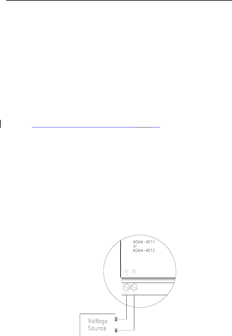
Calibration
8-
2
ADAM 4000 Series User’s Manual
Analog input/output modules are calibrated when you receive them.
However, calibration is sometimes required. No screwdriver is
necessary because calibration is done in software. Calibration
parameters are stored in the ADAM module’s onboard EEPROM.
The ADAM modules come with utility software that supports the
calibration of analog input and analog output. Aside from the
calibration that is carried out through software, the modules incorporate
automatic Zero Calibration and automatic Span Calibration at boot-up
or reset.
8.1 Analog Input Module Calibration
Models: ADAM-4011, 4011D, 4012, 4016, 4017, 4017+, 4018, 4018+,
4018M, 4019+
1. Set modules as initial mode before applying power to the module
and let it warm up for about 30 minutes
2. Assure that the module is correctly installed and is properly
configured for the input range that you want to calibrate. You can
do this by using the ADAM utility software. (Please refer to
Appendix D, Utility Software.)
3. Use a precise voltage source to calibrate the module through +IN
and -IN terminals for ADAM-4011, 4011D and 4012. However, for
ADAM-4016, the calibrating voltage should be applied to terminals
Vin+ and Vin- (or Iin+ and Iin-). At last, Vin0+ and Vin0- are used
for calibration in ADAM-4017, 4017+, 4018, 4018+, 4018M, 4019
and 4019+ models.
Figure 8-1 Applying Calibration Voltage
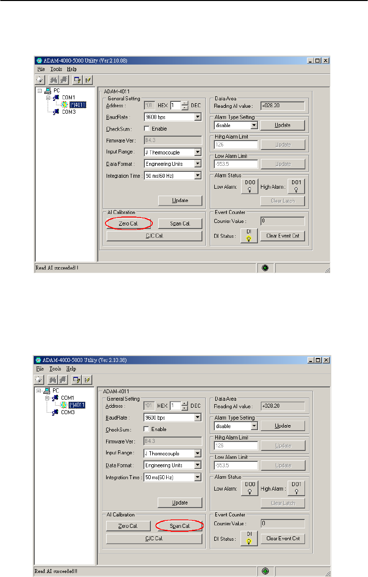
Chapter 8
Chapter 8 Calibration
8-3
4. Execute the Offset Calibration command. This is also done through
the ADAM utility software. (Please see “Offset Calibration” option
in the Calibration sub-menu of the ADAM utility software).
Figure 8-2 Zero Calibration
5. Execute the Span Calibration command. This can be done through
the ADAM utility software. (Please see “Span Calibration” option in
the Calibration sub-menu of the ADAM utility software).
Figure 8-3 Span Calibration
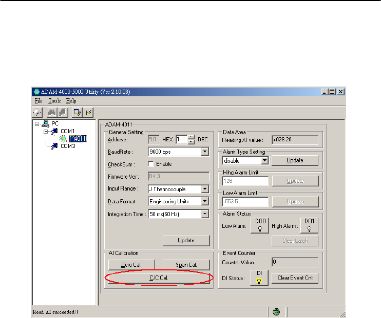
Calibration
8-
4
ADAM 4000 Series User’s Manual
6. This step is only for ADAM 4011, 4011D, 4018, 4018+, 4018M,
4019, 4019+. Execute the CJC (cold junction sensor) calibration
command. This is also done through the ADAM utility software.
(Please see “CJC Calibration” option in the Calibration sub-menu of
the ADAM utility software).
Figure 8-4 Cold Junction Calibration
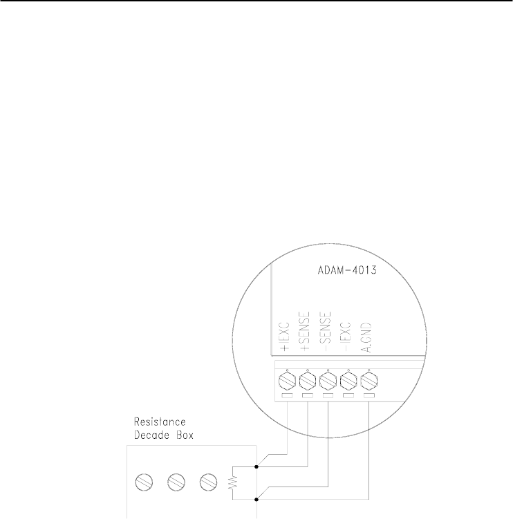
Chapter 8
Chapter 8 Calibration
8-5
8.2 Analog Input Resistance Calibration
Model: ADAM-4013
1. Apply power to the module and let it warm up for about 30 minutes.
2. Assure that the module is correctly installed and is properly
configured for the input range that you want to calibrate. You can do
this by using the ADAM utility software. (Please refer to Appendix
D, Utility Software.)
3. Apply the reference Span resistance to the screw terminals using a
4-wire connection. Please refer to Figure 8-5 for the correct wiring
diagram and Table 8-2 for the right Span calibration resistance).
Figure 8-5 Applying calibration resistance
Use a precision resistance decade box or discrete resistors with values:
10 W, 15 W, 60 W, 140 W, 200 W and 440 W.
4. Apply the reference Offset resistance to the terminals of the module.
(Please refer to Figure 8-5 for the correct wiring diagram and Table
8-2 for the right Offset calibration resistance.)
5. Issue an Offset Calibration command to the module. This can be
done by using the Calibrate option in the ADAM utility software
(Please see Appendix D, Utility Software)
6. Issue a Span Calibration command to the module. This can be done
through the Calibrate option in the ADAM utility software (Please
see Appendix D, Utility Software)

Calibration
8-
6
ADAM 4000 Series User’s Manual
Table 8-2 Calibration Resistance
Module Input
Range
Code
(Hex)
Input Range Span
Calibration
Resistance
Offset
Calibration
Resistance
4013 20 Pt, -100~100 ℃
a = 0.00385
140
Ω
60 Ω
21 Pt, 0~100 ℃
a = 0.00385
140
Ω
60 Ω
22 Pt, 0~200 ℃
a = 0.00385
200
Ω
60 Ω
23 Pt, 0~600 ℃
a = 0.00385
440
Ω
60 Ω
24 Pt, -100~100 ℃
a = 0.003916
140
Ω
60 Ω
25 Pt, 0~100 ℃
a = 0.003916
140
Ω
60 Ω
26 Pt, 0~200 ℃
a = 0.003916
200
Ω
60 Ω
27 Pt, 0~200 ℃
a = 0.003916
440
Ω
60 Ω
28 Ni, -80~100 ℃ 200
Ω
60 Ω
29 Ni, 0~100 ℃ 200
Ω
60 Ω
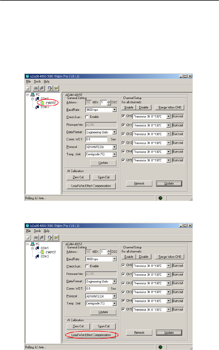
Chapter 8
Chapter 8 Calibration
8-7
8.3 Analog Input Thermistor module Calibration
Model: ADAM-4015T
If you select the range “Thermistor 3K 0~100C”, please follow the
calibration steps as below.
1. Short the INIT* pin to GND and then power up ADAM-4015T.
Run ADAM-4000-5000 Utility and search for the module.
2. Click on “Lead Wire Effect Compensation”
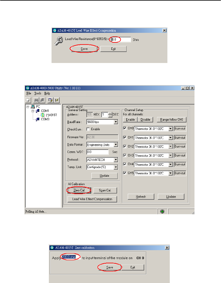
Calibration
8-
8
ADAM 4000 Series User’s Manual
3. Set the resistance to “0” and click on “Save”
4. Click on “Zero Cal.”
5. Apply 200.0 ohms resistor with 0.01% accuracy to CH0 and then
Click on “Save”
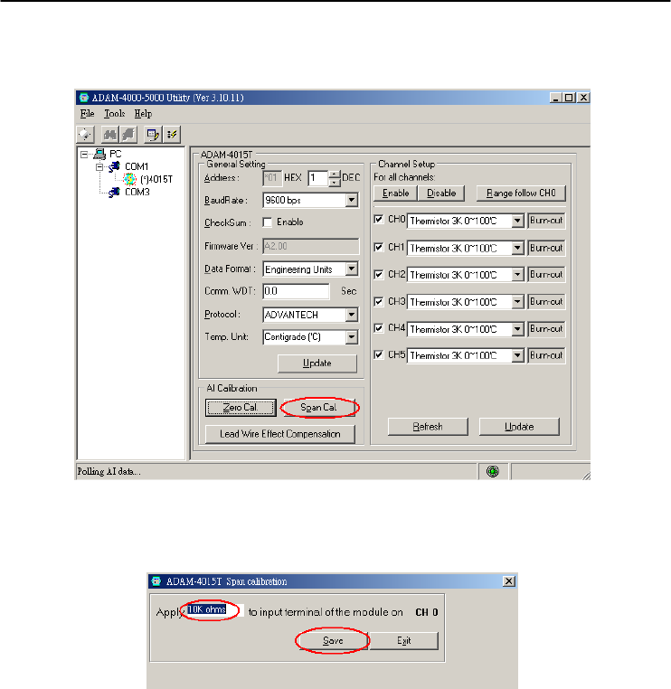
Chapter 8
Chapter 8 Calibration
8-9
6. Click on “Span Cal.”
7. Apply 10K ohms resistor with 0.01% accuracy to CH0 and then
Click on “Save”
8. Finished!
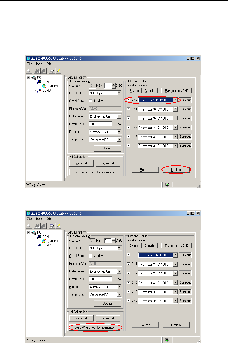
Calibration
8-
10
ADAM 4000 Series User’s Manual
If you select the range “Thermistor 10K 0~100C”, please follow the
calibration steps as below.
1. Change the input range to “Thermistor 10K 0~100C” and click on
“Update”
2. Click on “Lead Wire Effect Compensation”
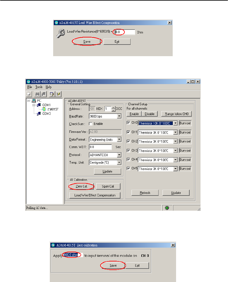
Chapter 8
Chapter 8 Calibration
8-11
3. Set the resistance to “0” and click on “Save”
4. Click on “Zero Cal.”
5. Apply 800.0 ohms resistor with 0.01% accuracy to CH0 and then
Click on “Save”
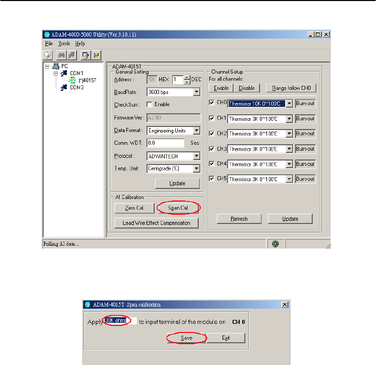
Calibration
8-
12
ADAM 4000 Series User’s Manual
6. Click on “Span Cal.”
7. Apply 30K ohms resistor with 0.01% accuracy to CH0 and then
Click on “Save”
8. Finished!
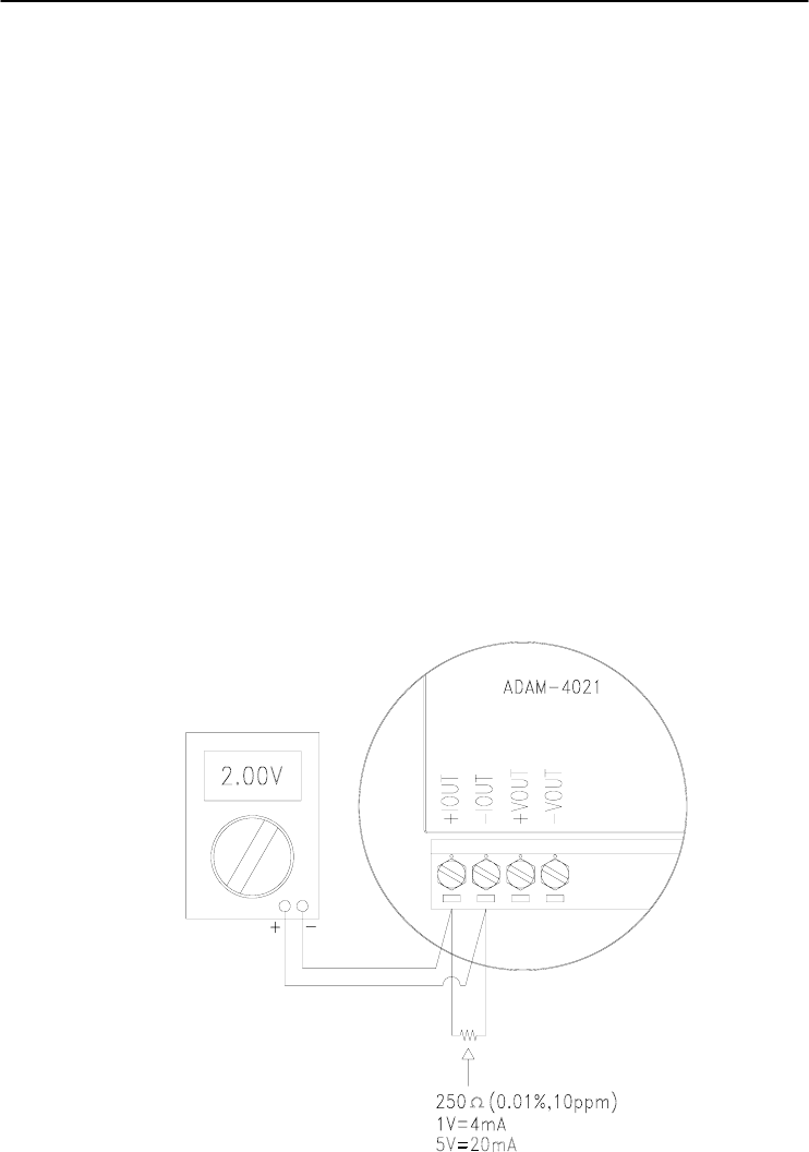
Chapter 8
Chapter 8 Calibration
8-13
8.4 Analog Output Calibration
Model: ADAM-4021/4024
The output current of analog output modules can be calibrated by using
a low and high calibrating value. The analog output modules can be
configured in one of the two ranges, 0-20 mA and 4-20 mA. Since the
low limit of the 0 - 20 mA ranges, 0 mA, is an absolute reference (no
power, or immeasurably small power). However, just two levels, 4 mA
and 20 mA, are needed for calibration.
1. Apply power to the analog output module and let it warm up for
about 30 minutes.
2. Assure that the module is correctly installed, and its configuration is
according to your specifications. It should match the output range
that you want to calibrate. You can do this by using the ADAM
utility software. (Please refer to Appendix D, Utility Software.)
3. Connect either a 5-digit millimeter or voltmeter with a shunt resistor
(250Ω, 0.01% , and 10ppm) to the screw terminals of the module
Figure 8-6 Setup for Analog Output Calibration

Calibration
8-
14
ADAM 4000 Series User’s Manual
4. Issue the Analog Data Out command to the module with an output
value of 4 mA.
5. Check the actual output value at the terminals. If it does not equal
to 4 mA, use the “Trim” option in the “Calibrate” sub menu to
change the actual output. Trim the module until the millimeter
indicates exactly 4 mA. In the case of using a voltage meter with
shunt resistor, the voltage meter should indicate exactly 1 V. (When
calibrating for 20 mA using voltage meter and shunt resistor, the
correct voltage would be 5 V.)
6. Issue the 4 mA Calibration command to indicate that the output is
calibrated. The calibrated parameters should be stored in the
modules EEPROM.
7. Execute an Analog Data Out command with an output value of 20
mA, and the output will approximately be 20 mA.
8. Continue executing the Trim Calibration command until the output
current is equal to exactly 20 mA.
9. Execute the 20 mA Calibration command until the present output is
exactly 20 mA. The analog output module will store its calibrated
parameters in EEPROM.
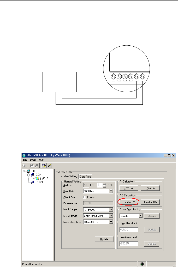
Chapter 8
Chapter 8 Calibration
8-15
Module: ADAM-4016
1. Apply power to the strain gauge input module and let it warm up for
about 30 minutes.
2. Assure that the module is correctly installed. Then, connect a
voltmeter to the screw terminals of the module.
Exc-
Voltmeter
-+
Exc+
Iin-
Iin+
Vin-
Vin+
ADAM-4016
Figure 8-7 Setup for Voltage Output Calibration
3. Execute the Zero Calibration command. This is done through the
ADAM utility software. (Please see "A/O 0V Calibration" option in
the Calibration sub-menu of the ADAM utility software.)
Figure 8-8 Zero Calibration
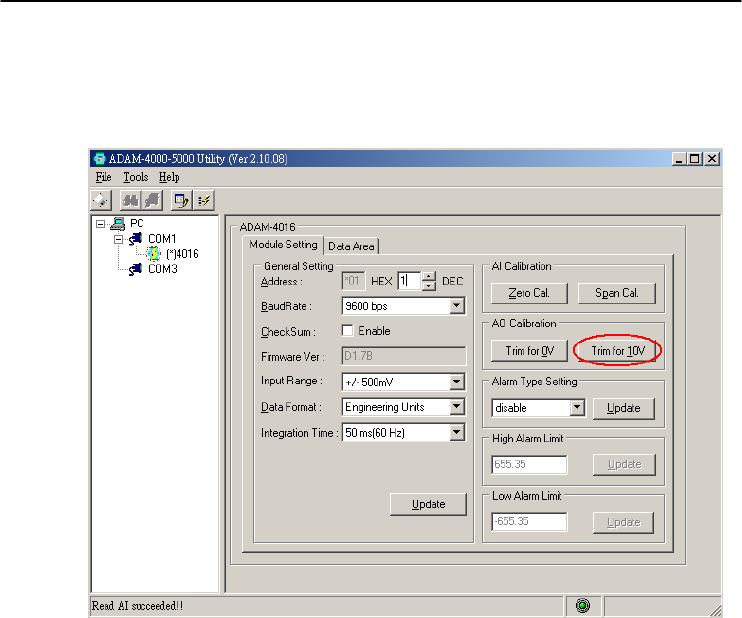
Calibration
8-
16
ADAM 4000 Series User’s Manual
4. Execute the Span Calibration command. This can be done through
the ADAM utility software. (Please see "A/O 10 V Calibration"
option in the Calibration sub-menu of the ADAM utility software.)
Figure 8-9 Span Calibration
5. Check the actual output value at the terminals. If this does not equal
0 V or 10 V, use the Trim Calibration command to change the
output value. This is done through the ADAM utility software.
(Use the arrow key to adjust the output value after executing the
"A/O 0V Calibration" or "A/O 10 V Calibration". Right and Up
keys mean increasing, and Left and Down keys mean decreasing).
Technical Specifications A

Technical Specifications
A-
2
ADAM 4000 Series User’s Manual
A.1 ADAM-4011 Thermocouple Input Module
Table A-1 ADAM-4011 Specifications
T/C channel number 1
Input range
J, K, T, E, R, S and B Thermocouple
±15 mV, ±50 mV, ±100 mV, ±500mV,
±1 V, ±2.5 V and ±20mA
Output
speed (in bps)
Maximum distance
RS-485 (2-Wire)
1200, 2400, 4800, 9600, 19.2K, 38.4K,
57.6K, 115.2K
4000 ft. (1200 m.)
Accuracy ±0.05% or better
Zero drift ±6V/℃
Span drift ±25 ppm/℃
Isolation-rated voltage 3000 VDC
CMR @ 50/60 Hz 150 dB
NMR @ 50/60 Hz 100 dB
Resolution 16-bit
Sampling rate 10 samples/second
Input impedance Voltage: 2 M, Current: 125
Digital output
Sink current
Power dissipation
2 channels open collector to 30 V
30 mA maximum load
300 mW
Digital input
Logic level 0
Logic level 1
Pull up current
1 channel
+1 V maximum
+3.5 to +30 V
0.5 mA
Event counter
Max. input frequency
Min. pulse width
50 Hz
1 msec
Support protocol ADAM ASCII
Watchdog timer 1.6 second (System)
Power supply +10 to +30 VDC (non-regulated)
Power consumption 1.4 W @ 24 VDC
Burn-out detection Yes

Appendix A
Appendix A Technical Specification A
-3
Table A-2 ADAM-4011 Range Accuracy for Thermocouple
Input
Range
Code
(Hex)
Input Range Typical
Accuracy
Maximum
Error Units
0E J thermocouple
0 to760 ℃ ±0.5 ±0.75
℃
0F K thermocouple
0 to 1370 ℃ ±0.5 ±0.75
℃
10 T thermocouple
-100 to 400 ℃ ±0.5 ±0.75
℃
11 E thermocouple
0 to 1000 ℃ ±0.5 ±0.75
℃
12 R thermocouple
500 to 1750 ℃ ±0.6 ±1.5
℃
13 S thermocouple
500 to 1750 ℃ ±0.6 ±1.5
℃
14 B thermocouple
500 to 1800 ℃ ±1.2 ±2.0
℃
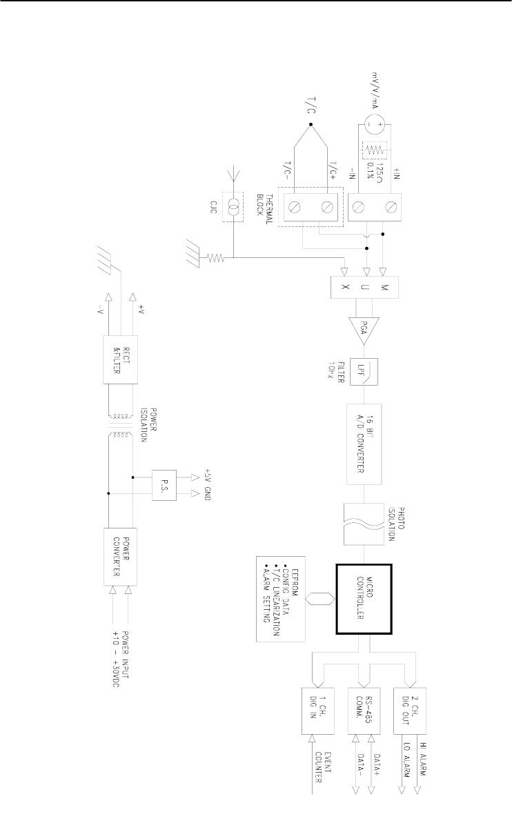
Technical Specifications
A-
4
ADAM 4000 Series User’s Manual
Figure A-1 ADAM-4011 Function Diagram

Appendix A
Appendix A Technical Specification A
-5
A.2 ADAM-4011D Thermocouple Input Module with LED
Display
Table A-3 ADAM-4011D Specifications
T/C channel number 1
Input range
J, K, T, E, R, S and B Thermocouple
±15 mV, ±50 mV, ±100 mV, ±500mV,
±1 V, ±2.5 V and ±20mA
Output
speed (in bps)
Maximum distance
RS-485 (2-Wire)
1200, 2400, 4800, 9600, 19.2K, 38.4K,
57.6K, 115.2K
4000 ft. (1200 m.)
Accuracy ±0.05% or better
Zero drift ±6 V/℃
Span drift ±25 ppm/℃
Isolation-rated voltage 3000 VDC
CMR @ 50/60 Hz 150 dB
NMR @ 50/60 Hz 100 dB
Resolution 16-bit
Sampling rate 10 samples/second
Input impedance Voltage: 2 M, Current: 125
LED indicator 5 digit readout
Digital output
Sink current
Power dissipation
2 channels open collector to 30 V
30 mA maximum load
300 mW
Digital input
Logic level 0
Logic level 1
Pull up current
1 channel
+1 V maximum
+3.5 to +30 V
0.5 mA
Event counter
Max. input frequency
Min. pulse width
50 Hz
1 msec
Support protocol ADAM ASCII
Watchdog timer 1.6 second (System)
Power supply +10 to +30 VDC (non-regulated)
Power consumption 1.4 W @ 24 VDC
Burn-out detection Yes

Technical Specifications
A-
6
ADAM 4000 Series User’s Manual
Table A-4 ADAM-4011D Range Accuracy for Thermocouple
Input
Range
Code
(Hex)
Input Range Typical
Accuracy
Maximum
Error Units
0E J thermocouple
0 to 760 ℃ ±0.5 ±0.75
℃
0F K thermocouple
0 to 1370 ℃ ±0.5 ±0.75
℃
10 T thermocouple
-100 to 400 ℃ ±0.5 ±0.75
℃
11 E thermocouple
0 to 1000 ℃ ±0.5 ±0.75
℃
12 R thermocouple
500 to 1750 ℃ ±0.6 ±1.5
℃
13 S thermocouple
500 to 1750 ℃ ±0.6 ±1.5
℃
14 B thermocouple
500 to 1800 ℃ ±1.2 ±2.0
℃
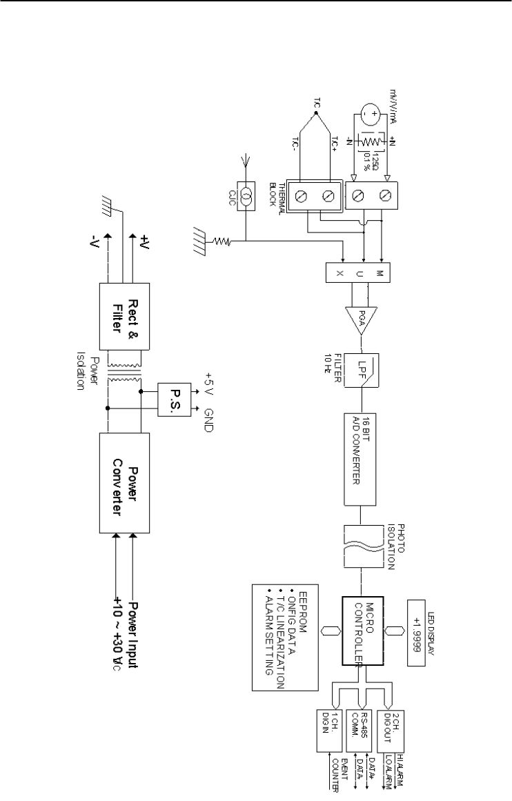
Appendix A
Appendix A Technical Specification A
-7
Figure A-2 ADAM-4011D Function Diagram

Technical Specifications
A-
8
ADAM 4000 Series User’s Manual
A.3 ADAM-4012 Analog Input Module
Table A-5 ADAM-4012 Specifications
AI channel number 1
Input range ±150 mV, ±500mV, ±1 V, ±5 V,
±10 V and ±20mA
Output
speed (in bps)
Maximum distance
RS-485 (2-wire)
1200, 2400, 4800, 9600, 19.2K, 38.4K,
57.6K, 115.2K
4000 ft. (1200 m.)
Accuracy ±0.05% or better
Zero drift ±6 V/℃
Span drift ±25 ppm/℃
Isolation-rated voltage 3000 VDC
CMR @ 50/60 Hz 150 dB
NMR @ 50/60 Hz 100 dB
Resolution 16-bit
Sampling rate 10 samples/second
Input impedance Voltage: 20 M, Current: 125
Digital output
Sink current
Power dissipation
2 channels open collector to 30 V
30 mA maximum load
300 mW
Digital input
Logic level 0
Logic level 1
Pull up current
1 channel
+1 V maximum
+3.5 to +30 V
0.5 mA
Event counter
Max. input frequency
Min. pulse width
50 Hz
1 msec
Support protocol ADAM ASCII
Watchdog timer 1.6 second (System)
Power supply +10 to +30 VDC (non-regulated)
Power consumption 1.2 W @ 24 VDC
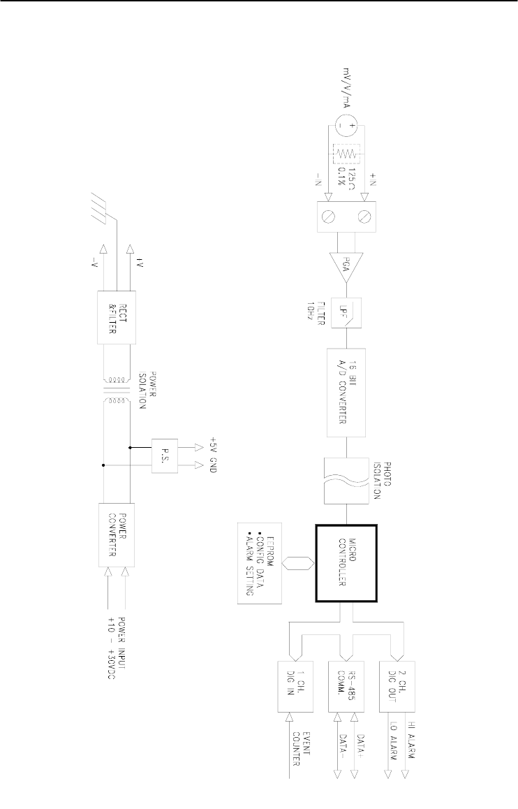
Appendix A
Appendix A Technical Specification A
-9
Figure A-3 ADAM-4012 Function Diagram

Technical Specifications
A-
10
ADAM 4000 Series User’s Manual
A.4 ADAM-4013 RTD Input Module
Table A-6 ADAM-4013 Specifications
RTD channel number 1
Input type Pt or Ni RTD
Output
speed (in bps)
Maximum distance
RS-485 (2-Wire)
1200, 2400, 4800, 9600, 19.2K, 38.4K,
57.6K, 115.2K
4000 ft. (1200 m.)
Accuracy ±0.1% or better
Zero drift ±3V/℃
Span drift ±25 ppm/℃
Input connections 2, 3 or 4 wires
Isolation-rated voltage 3000 VDC
CMR @ 50/60 Hz 150 dB
NMR @ 50/60 Hz 100 dB
Sampling rate 10 samples/second
Input impedance 2 M
Support protocol ADAM ASCII
Watchdog timer 1.6 second (System)
Power supply +10 to +30 VDC (non-regulated)
Power consumption 0.7 W @ 24 VDC

Appendix A
Appendix A Technical Specification A
-11
Figure A-4 ADAM-4013 Function Diagram

Technical Specifications
A-
12
ADAM 4000 Series User’s Manual
A.5 ADAM-4016 Analog Input/Output Module
Table A-7 ADAM-4016 Specifications
AI channel number 1
AI range ±15 mV, ±50 mV, ±100 mV, ±500 mV
and ±20 mA
Output
Speed (bps)
Maximum distance
RS-485 (2-wire)
1200, 2400, 4800, 9600, 19.2K, 38.4K,
57.6K, 115.2K
4000 ft. (1200 m)
Input impedance Voltage: 2 M, Current: 125
AI isolation voltage 3000 VDC
AI resolution 16-bit
AI sampling rate 10 samples/second
AI accuracy ±0.05% or better
AI zero drift ±6 V /℃
AI span drift ±25 ppm/℃
AI CMR @ 50/60 Hz 150 dB
AI NMR @ 50/60 Hz 100 dB
AO channel number 1
AO range 0~10 V
AO drive current 30 mA
AO isolation voltage 3000 VDC
AO accuracy 0.05% of FSR
AO drift ± 50 ppm/℃
Digital output
Sink current
Power dissipation
4 channels open collector to 30 V
30 mA maximum load
300 mW
Support protocol ADAM ASCII
Watchdog timer 1.6 second (System)
Power requirements +10 to +30 VDC (non-regulated)
Power consumption 2.2 W @ 24 VDC
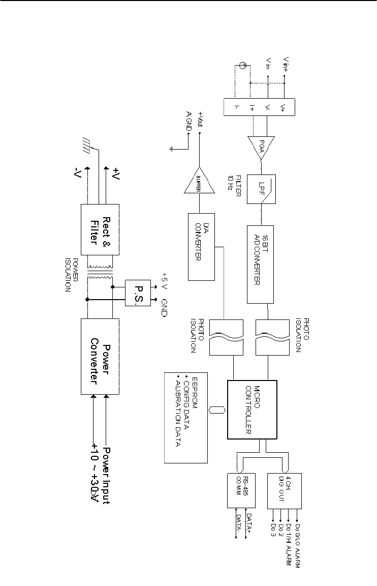
Appendix A
Appendix A Technical Specification A
-13
Figure A-5 ADAM-4016 Function Diagram

Technical Specifications
A-
14
ADAM 4000 Series User’s Manual
A.6 ADAM-4017/4017+ 8-Channel Analog Input Module
Table A-8 ADAM-4017/4017+ Specifications
AI channel number
ADAM-4017:
6 differential and 2 single-ended
ADAM-4017+:
8 differential
Input type mV, V and mA
Input range
ADAM-4017:
±150 mV, ±500 mV, ±1 V, ±5 V, ±10 V
and ±20 mA
ADAM-4017+:
±150 mV, ±500 mV, ±1 V, ±5 V, ±10 V,
±20 mA and 4~20 mA
Output
speed (bps)
Maximum distance
RS-485 (2-wire)
1200, 2400, 4800, 9600, 19.2K, 38.4K,
57.6K, 115.2K
4000 ft. (1200 m)
Isolation voltage 3000 VDC
Resolution 16-bit
Sampling rate 10 samples/second (total)
Bandwidth 13.1 Hz
Accuracy ±0.1% or better
Zero drift ±6 V/℃
Span drift ±25 ppm/℃
CMR @ 50/60 Hz 120 dB
NMR @ 50/60 Hz 100 dB
Input impedance Voltage: 20 M, Current: 120
Support protocol ADAM ASCII (ADAM-4017 & 4107+)
MODBUS/RTU (ADAM-4017+ only)
Watchdog timer
ADAM-4017: System (1.6 second)
ADAM-4017+:
System (1.6 second) and communication
Power requirements +10 to +30 VDC (non-regulated)
Power consumption 1.2 W @ 24 VDC
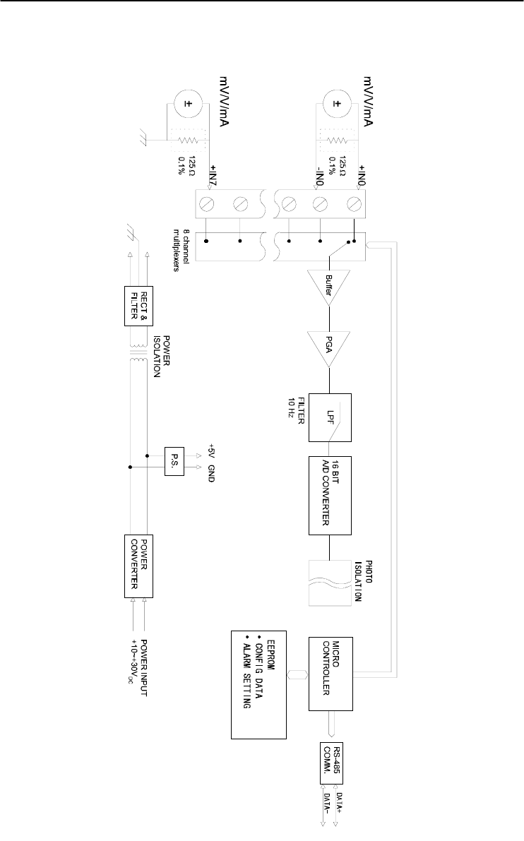
Appendix A
Appendix A Technical Specification A
-15
Figure A-6 ADAM-4017/4017+ Function Diagram

Technical Specifications
A-
16
ADAM 4000 Series User’s Manual
A.7 ADAM-4018/4018+ 8-channel Analog Input Module
Table A-9 ADAM-4018/4018+ Specifications
AI channel number
ADAM-4018:
6 differential and 2 single-ended
ADAM-4018+:
8 differential
Input type Thermocouple with mV, V, or mA
Input range
J, K, T, E, R, S and B Thermocouple
ADAM-4018:
±15 mV, ±50 mV, ±100 mV, ±500 mV,
±1 V, ±2.5 V and ±20 mA
ADAM-4018+:
±20 mA and 4~20 mA
Output
speed (bps)
Maximum distance
RS-485 (2-wire)
1200, 2400, 4800, 9600, 19.2K, 38.4K,
57.6K, 115.2K
4000 ft. (1200 m)
Isolation voltage 3000 VDC
Resolution 16-bit
Sampling rate 10 samples/second (total)
Bandwidth 13.1 Hz
Accuracy ±0.1% or better
Zero drift ±6 V/℃
Span drift ±25 ppm/℃
CMR @ 50/60 Hz 120 dB
NMR @ 50/60 Hz 100 dB
Input impedance Voltage: 20 M, Current: 120
Support protocol ADAM ASCII (ADAM-4018 & 4108+)
MODBUS/RTU (ADAM-4018+ only)
Watchdog timer
ADAM-4018: System (1.6 second)
ADAM-4018+:
System (1.6 second) and communication
Power requirements +10 to +30 VDC (non-regulated)
Power consumption 0.8 W @ 24 VDC
Burn-out detection All T/C inpu
t
(ADAM-4018+ onl
y
)

Appendix A
Appendix A Technical Specification A
-17
Table A-10 ADAM-4018/4018+ Range Accuracy for
Thermocouple
Input
Range
Code
(Hex)
Input Range Typical
Accuracy
Maximum
Error Units
0E J thermocouple
0 to 760 ℃ ±1.0 ±1.5 ℃
0F K thermocouple
0 to 1370 ℃ ±1.0 ±1.5 ℃
10 T thermocouple
-100 to 400 ℃ ±1.0 ±1.5 ℃
11 E thermocouple
0 to 1000 ℃ ±1.0 ±1.5 ℃
12 R thermocouple
500 to 1750 ℃ ±1.2 ±2.5 ℃
13 S thermocouple
500 to 1750 ℃ ±1.2 ±2.5 ℃
14 B thermocouple
500 to 1800 ℃ ±2.0 ±3.0 ℃
NOTE: Because the CJC sensor of ADAM-4018 is located in
the side of channel 0 to 4, the measurement will have the
difference ± 1 ℃ between channel 0 ~ 4 and channel 5 ~ 7.
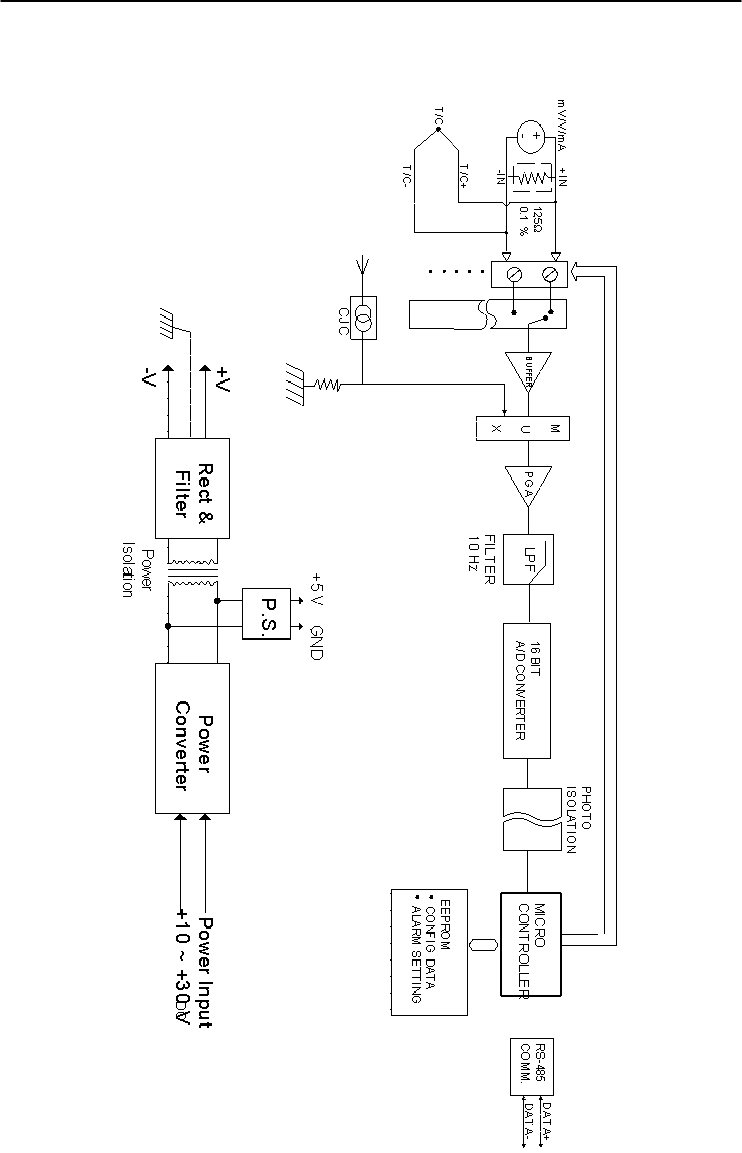
Technical Specifications
A-
18
ADAM 4000 Series User’s Manual
Figure A-7 ADAM-4018/4018+ Function Diagram

Appendix A
Appendix A Technical Specification A
-19
A.8 ADAM-4018M 8-channel Analog Input Data Logger
Table A-11 ADAM-4018M Specifications
AI channel number 6 differential and 2 single-ended
Input type mV, V and mA
Input range
J, K, T, E, R, S and B Thermocouple
±15 mV, ±50 mV, ±100 mV, ±500 mV, and
±20 mA
Output
speed (bps)
Maximum distance
RS-485 (2-wire)
1200, 2400, 4800, 9600, 19.2K, 38.4K,
57.6K, 115.2K
4000 ft. (1200 m)
Isolation voltage 500 VDC
Resolution 16-bit
Sampling rate 10 samples/sec(total)
Bandwidth 13.1 Hz
Accuracy ±0.1% or better
Zero drift ±6 μV/℃
Span drift ±25 ppm/℃
CMR @ 50/60 Hz 120 dB
NMR @ 50/60 Hz 100 dB
Input impedance Voltage: 20 M, Current: 120
Storage capacity
Standard log
Event log
Mixed log
128 KB Flash memory
38,000 samples (total)
16,300 samples (total)
16,300 data samples and 9,300 event
samples (total)
Storage type Write to end of memory, or circular memory
Logging mode Standard log, Event log or Mixed log
Sampling interval 2 second to 18 hours
Measurement duration 330 minutes to 20 years
Support protocol ADAM ASCII
Watchdog timer 1.6 second (System)
Power requirements +10 to +30 VDC (non-regulated)
Power consumption 1.8 W @ 24 VDC

Technical Specifications
A-
20
ADAM 4000 Series User’s Manual
Table A-12 ADAM-4018M Range Accuracy for Thermocouple
Input
Range
Code
(Hex)
Input Range Typical
Accuracy
Maximum
Error Units
0E J thermocouple
0 to 760 ℃ ±1.0 ±1.5 ℃
0F K thermocouple
0 to 1370 ℃ ±1.0 ±1.5 ℃
10 T thermocouple
-100 to 400 ℃ ±1.0 ±1.5 ℃
11 E thermocouple
0 to 1000 ℃ ±1.0 ±1.5 ℃
12 R thermocouple
500 to 1750 ℃ ±1.2 ±2.5 ℃
13 S thermocouple
500 to 1750 ℃ ±1.2 ±2.5 ℃
14 B thermocouple
500 to 1800 ℃ ±2.0 ±3.0 ℃
NOTE: Because the CJC sensor of ADAM-4018M is located in
the side of channel 0 to 4, the measurement will have the
difference ± 1 ℃ between channel 0 ~ 4 and channel 5 ~ 7.
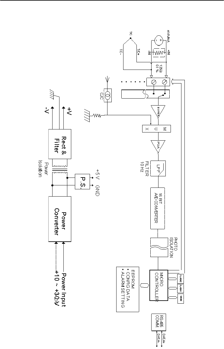
Appendix A
Appendix A Technical Specification A
-21
Figure A-8 ADAM-4018M Function Diagram

Technical Specifications
A-
22
ADAM 4000 Series User’s Manual
A.9 ADAM-4019+ 8-Channels Universal Analog Input
Module
Table A-13 ADAM-4019+ Specifications
AI channel number 8
Input type V, mV, mA and T/C
Input range
V: ±1 V , ±2.5 V, ±5 V , ±10 V
mV: ±100 mV , ±500 mV
mA: ±20 mA (with120 Ω resister)
4~20 mA(with 120 Ω resister)
Thermocouple:
J 0 to 760 ℃
K 0 to 1370 ℃
T -100 to 400 ℃
E 0 to 1400 ℃
R 500 to 1750 ℃
S 500 to 1750 ℃
B 500 to 1800 ℃
Isolation voltage 3000 VDC
Resolution 16-
b
it
Sampling rate 10 samples/sec (total)
Input impedance 20 M
Accuracy ±0.1% or better
Zero drift ±6 μV/℃
CMR @ 50/60 Hz 120 dB
NMR @ 50/60 Hz 100 dB
Span drift ±25 ppm/℃
Support protocol ADAM ASCII and MODBUS/RTU
Watchdog timer System (1.6 second) and communication
Power requirements +10 to +30 VDC (non-regulated)
Power consumption 1.0 W @ 24 VDC
Burn-out detection +4~20mA and all Thermocouple inpu
t
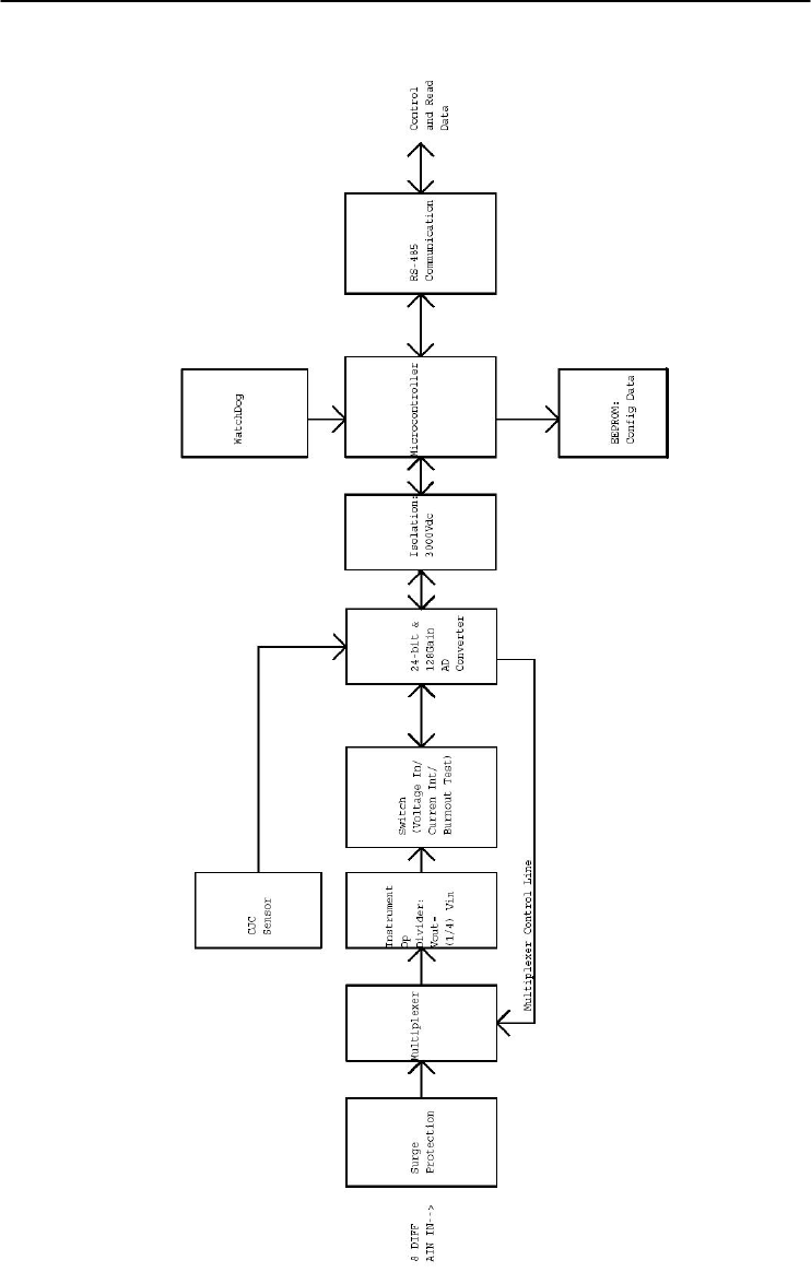
Appendix A
Appendix A Technical Specification A
-23
Figure A-9 ADAM-4019+ Function Diagram

Technical Specifications
A-
24
ADAM 4000 Series User’s Manual
A.10 ADAM-4021/4024 Analog Output Module
Table A-14 ADAM-4021/4024 Specifications
Input
speed (bps)
Maximum distance
RS-485 (2-wire)
1200, 2400, 4800, 9600, 19.2K, 38.4K,
57.6K, 115.2K
4000 ft. (1200 m)
AO channel number ADAM-4021: 1
ADAM-4024: 4
Output type mA, V
Output range 0~20 mA, 4~20 mA and ±10 V
Accuracy ADAM-4021:
±0.1% of FSR for current output
±0.2% of FSR for voltage output
ADAM-4024:
±0.1% of FSR for current output
±0.1% of FSR for voltage output
Resolution 12-bit
Readback accuracy ±0.1% of FSR (ADAM-4021 only)
Zero drift
voltage output
current output
±30 V/℃
±0.2 A/℃
Span temperature
coefficient ±25 ppm/℃
Isolation rated voltage 3000 VDC
Programmable output
slope
0.125 to 128 mA/second
0.0625 to 64 V/second
Current load resistor 0 to 500 Ω (source)
Bandwidth 100 samples/second
Output impedance 0.5
(Table continued on next page)

Appendix A
Appendix A Technical Specification A
-25
Support protocol ADAM-4021:
ADAM ASCII
ADAM-4024:
ADAM ASCII and MODBUS/RTU
Watchdog timer ADAM-4021:
System (1.6 second)
ADAM-4024:
System (1.6 second) and communication
Power supply +10 to +30 VDC (non-regulated)
Power consumption ADAM-4021:
1.4 W @ 24 VDC
ADAM-4024:
3.0 W @ 24 VDC
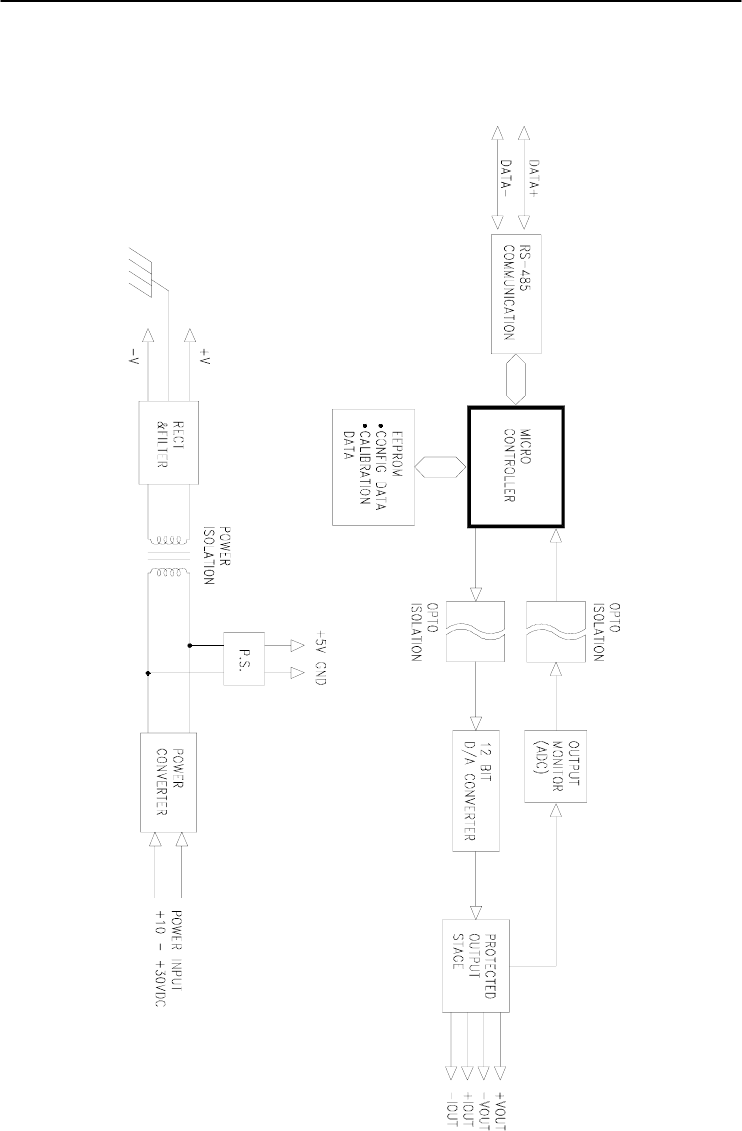
Technical Specifications
A-
26
ADAM 4000 Series User’s Manual
Figure A-10 ADAM-4021 Function Diagram
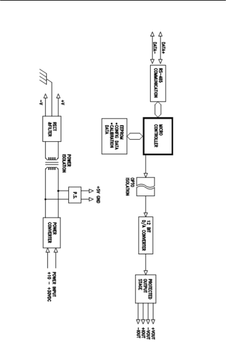
Appendix A
Appendix A Technical Specification A
-27
Figure A-11 ADAM-4024 Function Diagram

Technical Specifications
A-
28
ADAM 4000 Series User’s Manual
A.11 ADAM-4050 Digital I/O Module
Table A-15 ADAM-4050 Specifications
DI/O channel number 7 digital inputs
8 digital outputs
Input/Output
speed (bps)
Maximum distance
RS-485 (2-wire)
1200, 2400, 4800, 9600, 19.2K,
38.4K, 57.6K, 115.2K
4000 ft. (1200 m)
Digital output
Sink-current
Power dissipation
Open collector to 30 V
30 mA maximum
300 mW
Digital input level
Logic level 0
Logic level 1
Pull-up current
+1 V maximum
+3.5 to +30 V
0.5 mA, 10K resistor to +5 V
Support protocol ADAM ASCII
Watchdog timer 1.6 second (System)
Power supply +10 to +30 VDC (non-regulated)
Power consumption 0.4 W @ 24 VDC
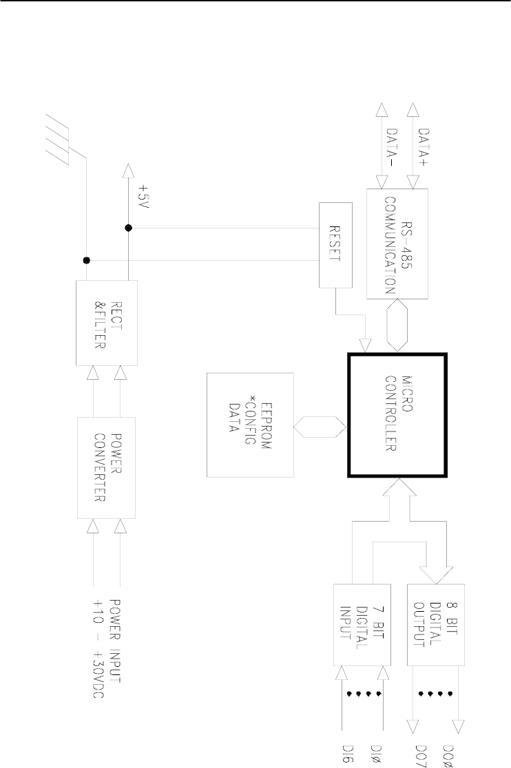
Appendix A
Appendix A Technical Specification A
-29
Figure A-12 ADAM-4050 Function Diagram

Technical Specifications
A-
30
ADAM 4000 Series User’s Manual
A.12 ADAM-4051/4052 Isolated Digital Input Module
Table A-16 ADAM-4051/4502 Specifications
DI/O channel number ADAM-4501: 16 digital inputs
ADAM-4052: 8 digital inputs
(6 fully independent isolated
channels, and 2 isolated channels
with common ground)
Input/Output
speed (bps)
Maximum distance
RS-485 (2-wire)
1200, 2400, 4800, 9600, 19.2K,
38.4K, 57.6K, 115.2K
4000 ft. (1200 m)
Digital input level
ADAM-4051:
Dry Contact:
Logic level 0:
Logic level 1:
Wet Contact:
Logic level 0:
Logic level 1:
ADAM-4052:
Logic level 0:
Logic level 1:
Close to GND
Open
+3V maximum
+10 to 50V
+1V maximum
+3 to 30V
Input resistance ADAM-4051: 5.2 kΩ
ADAM-4052: 3 kΩ
Isolation voltage ADAM-4051: 2500 VDC
ADAM-4052: 5000 VRMS
Over-voltage protect 70 VDC (ADAM-4051 only)
Support protocol ADAM-4051:
ADAM ASCII and MODBUS/RTU
ADAM-4052:
ADAM ASCII
(Table continued on next page)

Appendix A
Appendix A Technical Specification A
-31
Watchdog timer ADAM-4051:
System (1.6 second) and
communication
ADAM-4052:
System (1.6 second)
Power supply +10 to +30 VDC (non-regulated)
Power consumption ADAM-4051:1.0 W @ 24 VDC
ADAM-4052:0.4 W @ 24 VDC
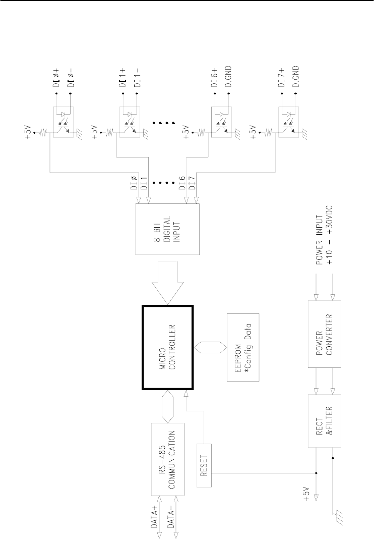
Technical Specifications
A-
32
ADAM 4000 Series User’s Manual
Figure A-13 ADAM-4051/4052 Function Diagram

Appendix A
Appendix A Technical Specification A
-33
A.13 ADAM-4053 16-channel Digital Input Module
Table A-17 ADAM-4053 Specifications
DI/O channel number 16 digital inputs
Input/Output
speed (bps)
Maximum distance
RS-485 (2-wire)
1200, 2400, 4800, 9600, 19.2K,
38.4K, 57.6K, 115.2K
4000 ft. (1200 m)
Digital input level
Dry Contact:
logic level 0:
logic level 1:
Wet Contact:
logic level 0:
logic level 1:
Close to GND
Open
+2V maximum
+4 to +30 V
Effective distance
(Dry contact only) 500 m maximum
Support protocol ADAM ASCII
Watchdog timer 1.6 second (System)
Power supply +10 to +30 VDC (non-regulated)
Power consumption 1.0 W @ 24 VDC
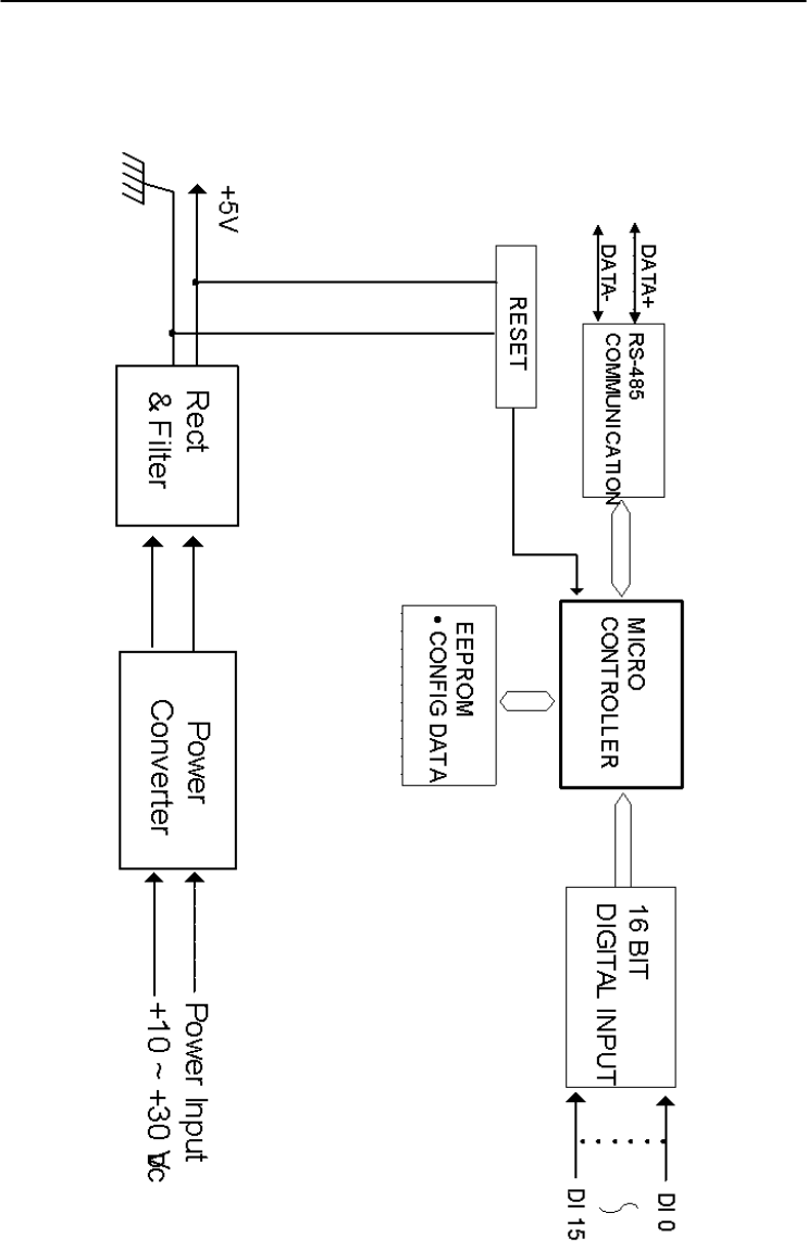
Technical Specifications
A-
34
ADAM 4000 Series User’s Manual
Figure A-14 ADAM-4053 Function Diagram

Appendix A
Appendix A Technical Specification A
-35
A.14 ADAM-4055 Isolated Digital Input/Output Module
Table A-18 ADAM-4055 Specifications
DI/O channel
number
8 digital inputs
8 digital outputs
Input/Output
speed (bps)
Maximum distance
RS-485 (2-wire)
1200, 2400, 4800, 9600, 19.2K, 38.4K,
57.6K, 115.2K
4000 ft. (1200 m)
Isolation voltage 2500 VDC
Opto-isolator
response time
25 µs
Over-voltage protect 70 VDC
ESD (Electro Static
Discharge)
2000 VDC
Digital input level
Dry Contact:
Logic level 0:
Logic level 1:
Wet Contact:
Logic level 0:
Logic level 1:
Open
Close to GND
+3V maximum
+10 to 50V
Digital output
Sink-current
Power dissipation
Open collector to 40 V
200 mA maximum
Channel: 1W maximum
Total: 2.2W (8 channels)
LED Indicator: On: Active
Off: Non-active
Support protocol ADAM ASCII and MODBUS/RTU
Watchdog timer System (1.6 second) and communication
Power supply +10 to +30 VDC (non-regulated)
Power consumption 1.0 W @ 24 VDC
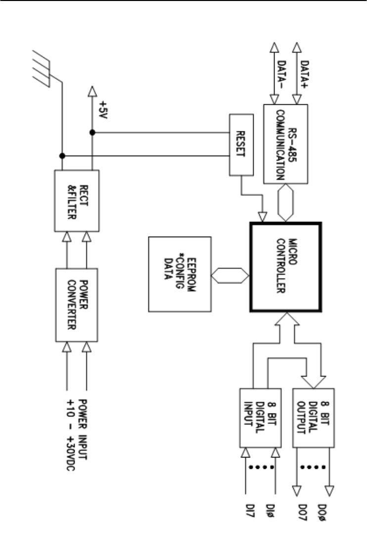
Technical Specifications
A-
36
ADAM 4000 Series User’s Manual
Figure A-15 ADAM-4055 Function Diagram

Appendix A
Appendix A Technical Specification A
-37
A.15 ADAM-4056S 12-channel Sink Type Isolated Digital
Output Module
Table A-19 ADAM-4056S Specifications
DO channel number 12 digital outputs (sink type)
Input/Output
speed (bps)
Maximum distance
RS-485 (2-wire)
1200, 2400, 4800, 9600, 19.2K, 38.4K,
57.6K, 115.2K
4000 ft. (1200 m)
Digital output
Power dissipation
Open Collector to +40V
200 mA maximum
Channel: 1W maximum
Total: 2.2W (8 channels)
Isolation voltage 5000 VDC
Support protocol ADAM ASCII and MODBUS/RTU
LED Indicator On: Active
Off: Non-active
Watchdog timer System (1.6 second) and communication
Power supply +10 to +30 VDC (non-regulated)
Power consumption 1.0 W @ 24 VDC
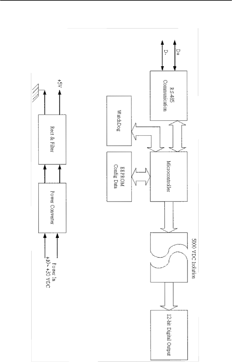
Technical Specifications
A-
38
ADAM 4000 Series User’s Manual
Figure A-16 ADAM-4056S Function Diagram

Appendix A
Appendix A Technical Specification A
-39
A.16 ADAM-4056SO 12-channel Source Type Isolated
Digital Output Module
Table A-20 ADAM-4056SO Specifications
DO channel number 12 digital outputs (source type)
Input/Output
speed (bps)
Maximum distance
RS-485 (2-wire)
1200, 2400, 4800, 9600, 19.2K, 38.4K,
57.6K, 115.2K
4000 ft. (1200 m)
Digital output VCC: +10~ +35V
1A (per Channel)
Isolation voltage 5000 VDC
Support protocol ADAM ASCII and MODBUS/RTU
LED Indicator On: Active
Off: Non-active
Watchdog timer System (1.6 second) and communication
Power supply +10 to +30 VDC (non-regulated)
Power consumption 1.0 W @ 24 VDC
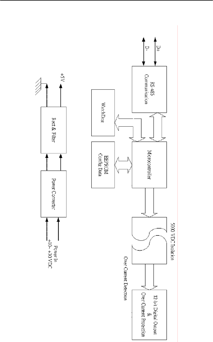
Technical Specifications
A-
40
ADAM 4000 Series User’s Manual
Figure A-17 ADAM-4056SO Function Diagram

Appendix A
Appendix A Technical Specification A
-41
A.17 ADAM-4060 Relay Output Module
Table A-21 ADAM-4060 Specifications
DO channel number 4 channel relay
(2 form A, 2 form C)
Input
speed (bps)
Maximum distance
RS-485 (2-wire)
1200, 2400, 4800, 9600, 19.2K,
38.4K, 57.6K, 115.2K
4000 ft. (1200 m)
Contact rating
(Resistive)
AC: 0.6 A@125 V
0.3 A@250 V
DC: 2 A@30 V
0.6 A@ 110 V
Breakdown voltage 500 VAC (50/60 Hz)
Relay on time (typical) 3 ms
Relay off time (typical) 2 ms
Total switching time 10 ms
Insulation resistance 1 G minimum at 500 VDC
Support protocol ADAM ASCII
Watchdog timer 1.6 second (System)
Power supply +10 to +30 VDC (non-regulated)
Power consumption 0.8 W @ 24 VDC
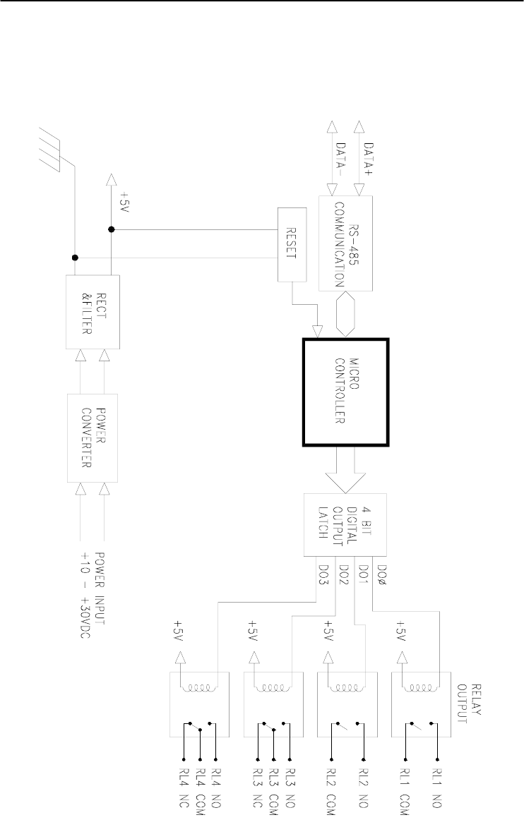
Technical Specifications
A-
42
ADAM 4000 Series User’s Manual
Figure A-18 ADAM-4060 Function Diagram

Appendix A
Appendix A Technical Specification A
-43
A.18 ADAM-4068/4069 8-channel Relay Output Module
Table A-22 ADAM-4068/4069 Specifications
DO channel number 8 channel relay
(4 form A, 4 form C)
Contact rating
(Resistive)
ADAM-4068:
AC: 0.6A @ 125V
0.3A @ 250V
DC: 2A @ 30V
0.6 @ 110V
ADAM-4069:
AC: 5A @ 240V
DC: 5A @ 30V
Breakdown voltage ADAM-4068:
500 VAC (50/60 Hz)
ADAM-4069:
1000 VAC (50/60 Hz)
Insulation resistance 1 G minimum at 500 VDC
Relay on time (typical) ADAM-4068: 3 ms
ADAM-4069: 5 ms
Relay off time (typical) ADAM-4068: 4 ms
ADAM-4069: 5.6 ms
Support protocol ADAM ASCII and MODBUS/RTU
Watchdog timer System (1.6 second) and
communication
Power supply +10 to +30 VDC (non-regulated)
Power consumption ADAM-4068:
0.6 W @ 24 VDC
ADAM-4069:
2.2 W @ 24 VDC
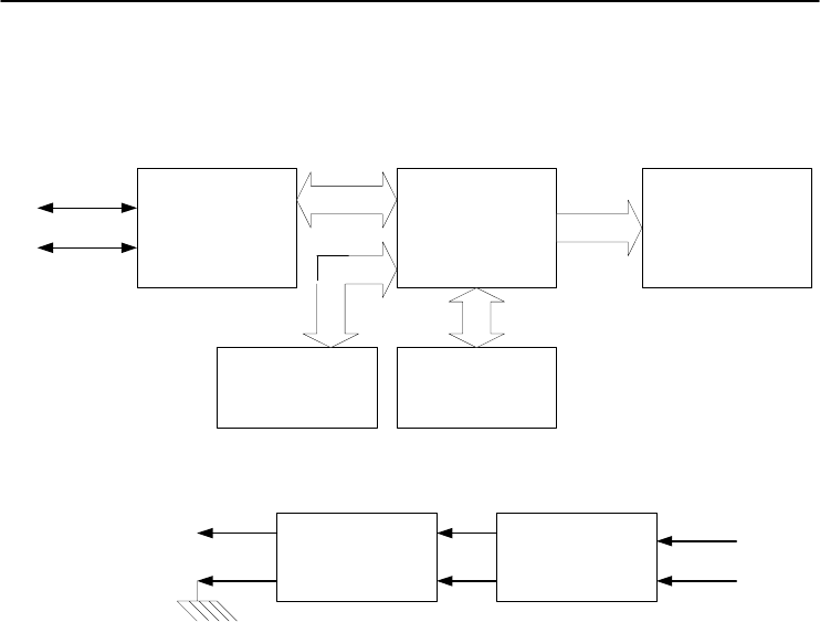
Technical Specifications
A-
44
ADAM 4000 Series User’s Manual
Figure A-19 ADAM-4068/4069 Function Diagram
RS-485
Communication Microcontroller 8-Channel Relay Output
Power ConverterRect & Filter
WatchDog
D+
D-
EEPROM
Config Data
Power In
+10~ +30 VDC
+5V

Appendix A
Appendix A Technical Specification A
-45
A.19 ADAM-4080 Counter/Frequency Input Module
Table A-23 ADAM-4080 Specifications
Input channel number 2 independent 32-bit counters
Input frequency 50 kHz maximum
Input mode Isolated or non-isolated
Isolation input level
Logic level 0
Logical level 1
+1 V maximum
+3.5 V to +30 V
Isolation voltage 2500 VRMS
Non-isolation input level
Logic Ievel 0
Logic level 1
Programmable threshold
0 to +5 V (default = 0.8 V)
0 to +5 V (default = 2.4 V)
Input pulse width >10 sec
Maximum count 4,294,967,295 (32 bits)
Programmable digital
noise filter
2 sec to 65 msec
Alarming Alarm comparators on each counter
Preset type Absolute or relative
Frequency measurement
Range
Programmable built-in
gate time
5 Hz to 50 KHz
1.0/0.1 sec
Digital output channels
Sink current
Power dissipation
2 channels open collector to 30 V
30 mA max. load
300 mW
Support protocol ADAM ASCII
Watchdog timer 1.6 second (System)
Power requirements +10 to +30 VDC (non-regulated)
Power consumption 2.0 W@ 24 VDC
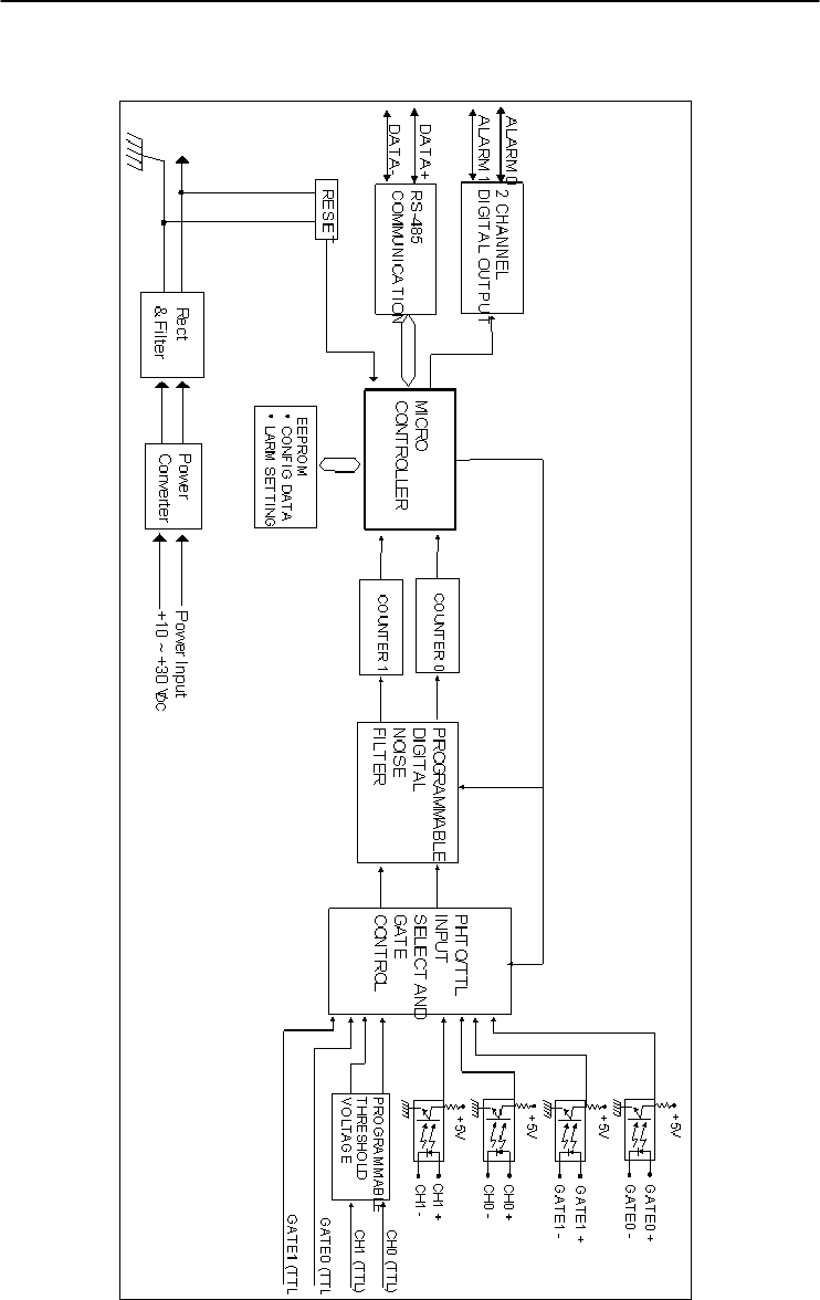
Technical Specifications
A-
46
ADAM 4000 Series User’s Manual
Figure A-20 ADAM-4080 Function Diagram

Appendix A
Appendix A Technical Specification A
-47
A.20 ADAM-4080D Counter/Frequency Input Module with
LED Display
Table A-24 ADAM-4080D Specifications
Input channels 2 independent 32-bit counters
Input frequency 50 kHz maximum
Input mode Isolated or non-isolated
Isolation input level
Logic level 0
Logical level
+1 V max
+3.5 V to +30 V
Isolation voltage 2500 VRMS
Non-isolation input level
Logic Ievel 0
Logic level 1
Programmable threshold
0 to +5 V (default = 0.8 V)
0 to +5 V (default = 2.4 V)
Input pulse width >10 sec
Maximum count 4,294,967,295 (32 bits)
Programmable digital
noise filter
2 sec to 65 msec
Alarming High and Low comparators on counter 0
Frequency Measurement
Range
Programmable built-in
gate time
5 Hz to 50 KHz
1.0/0.1 sec
Display LED indicator 5-digit readout; CH 0 or
CH 1 (programmable)
Digital Output Channels
Sink current
Power dissipation
2 channels Open collector to 30 V
30 mA max. load
300 mW
Support protocol ADAM ASCII
Watchdog timer 1.6 second (System)
Power requirements +10 to +30 VDC (non-regulated)
Power consumption 2.0 W @ 24 VDC
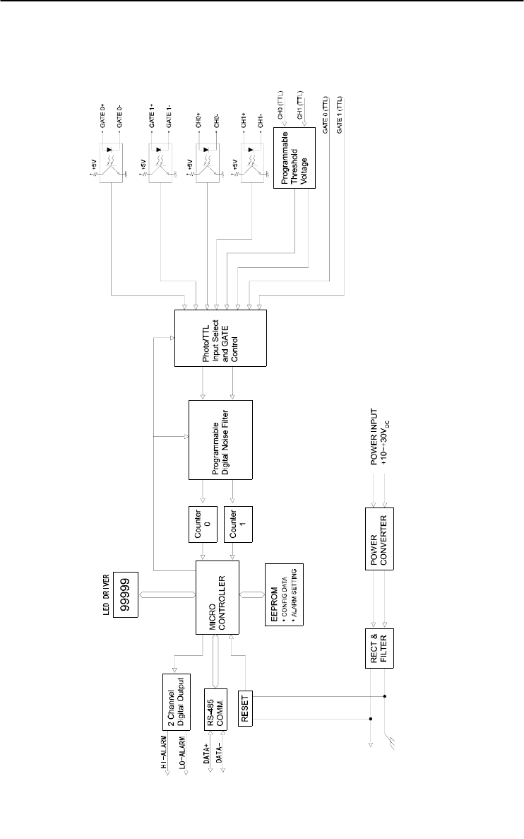
Technical Specifications
A-
48
ADAM 4000 Series User’s Manual
Figure A-21 ADAM-4080D Function Diagram
Data Formats and I/O Ranges B

Data Formats and I/O Ranges
B-
2
ADAM 4000 Series User’s Manual
B.1 Analog Input Formats
The ADAM analog input modules can be configured to transmit data to
the host in one of the following data formats:
-Engineering Units
-Percent of FSR
-Twos complement hexadecimal
-Ohms
B.1.1 Engineering Units
Data can be represented in engineering units by assigning bits 0 and 1
of the data format/checksum/integration time parameter with value 00.
This format presents data in standard units such as degrees, volts,
millivolts and milliamps. When the value in engineering format is
converted to computer language, it is presented in seven characters.
These characters may include sign and decimals. However, the number
of characters can not exceed seven.
Data is grouped into a plus (+) or minus (-) sign, followed by five
decimal digits and a decimal point. The input range which is employed
determines the resolution or the number of decimal places used as
illustrated in the following examples:
Example 1
The input value is -2.65 and the corresponding analog input module is
configured for a range of ±5 V. The response to the Analog Data In
command is: -2.6500 (cr)
Example 2
The input value is 305.5o C, and the analog input module is configured
for a type J thermocouple whose range is (0o C to 760o C). The response
to the Analog Data In command is: +305.50 (cr)
Example 3
The input value is +5.653 V. The analog input module is configured for
a ±5 V range. When the engineering unit format is used, the ADAM
Series analog input modules are configured so that they automatically
provide an over-range capability. The response to the Analog Data In
command in this case is: +5.6530 (cr)

Appendix B
Appendix B Data Formats and I/O Ranges B
-3
B.1.2 Percent of FSR
This mode is used by setting bits 0 and 1 of the data format/checksum
/integration time parameter to 01. The format used in Percent of FSR
consists of a plus (+) or minus (-) sign followed by five decimal digits
including a decimal point. The maximum possible resolution is 0.01%
with the decimal point fixed.
Data are given as the ratio of the input signal to the full-scale range.
Example 1
The input value is +2.0 V. The input module is configured for a range
of ±5 V. The response to the Analog Data In command is as follows:
+040.00 (cr)
The full calibrated voltage range ranges from -100% to 100% as
voltage input ranges are always bipolar. A ±5 V input would range
from -5 V
(-100%) to 5 V (100%).
In this example the input is represented by +40% of the full-scale range
which equals to (+(40/100) x 5 V = +2.0 V) the actual input value.
Example 2
The input value is 652.5o C, and a type E thermocouple (0o C to 1000o C)
is configured in the analog input module. The response to the Analog
Data In command is:
+065.25 (cr)
The result shows that the value of the input (652.5o C) is 65.25% of the
full-scale range (1000o C).
Thermocouple input ranges are always assumed to be bipolar with zero
being the point of symmetry. This holds true regardless of the specified
range of operation. For example, when we use a type J thermocouple
(0o C to 760o C), 760o C corresponds to +100% and 0o C corresponds to
0%. Even if 0o C lies outside of the specified operation range for the
thermocouple, zero will remain as the point of symmetry. For instance,
a type B thermocouple is specified for operation from +500o C to
+1800o C. In this case +1800o C corresponds to + 100% and 500o C
corresponds to +27.77%.

Data Formats and I/O Ranges
B-
4
ADAM 4000 Series User’s Manual
The percentage is related to the full span of the configured range. For
instance, a nickel RTD is specified for -80o C to +100o C. Then, the
lower value of -80o C equals to 0% of span and the upper value of +100o
C equals to 100% of span.
In the FSR mode, an over-range feature is automatically invoked by the
ADAM analog input modules if the value exceeds the uppermost value
of the input range. For instance, an analog module which is configured
for a ±5 V range has one of the values reading + 5.5V. The resulting
value would then be 110%.
The readings must fall within the input range for accuracy assurance.
Although they are typically linear readings, anything which falls
between ±100% and ±115% limits may not be accurate. Furthermore,
readings beyond these limits are neither accurate nor linear.
B.1.3 Twos complement hexadecimal
Twos Complement Hexadecimal format presents the data in ASCII
hexadecimal form providing a rapid communication, high resolution
and easy conversion to computer-compatible integer format.
In order to indicate twos complement hexadecimal, bits 0 and 1 of the
data format/checksum/integration time parameter must be set to 10.
This format displays data in the form of a 4-character hexadecimal
string.
This string represents a 16-bit twos complement binary value. Positive
full scale is denoted as 7FFF (+32,767) while negative full scale is
represented by the value 8000 (-32,768). The resolution is digit one at
the least significant bit (LSB) of 16 bits.
Example
The input value is -1.234 V. An analog input module is configured for a
±5 V range. The value returned is: E069 (cr)
This value is equivalent to the signed integer -8087.
Input ranges with voltage and milliamp values are used with the full
calibrated voltage range from 8000 to 7FFF. For instance, an ADAM-
4011 module is given a ±5 V input range. In this case, -5 V is
represented as 8000h and +5 V is denoted as 7FFFh.
When thermocouple input ranges are used, an input range which is
bipolar and symmetric at zero is assumed. The following table provides
several examples.

Appendix B
Appendix B Data Formats and I/O Ranges B
-5
Thermocouple
Type
Temperature Range
(Degrees)
Temperature Range
(Hex)
J 0° C to 760° C 0000h - 7FFFh
T -100° C to 400° C E000h - 7FFFh
R 500° C to 1750° C 2492h - 7FFFh
The given span of the specified range is used to determine the RTD
input ranges for twos complement hexadecimal values. For an example,
if the nickel RTD is specified for the range -80o C to +100o C, the
corresponding values in hexadecimal notation would be 8000h to
7FFFh.
B.1.4 Ohms
To indicate ohms, set bits 0 and 1 of the data
format/checksum/integration time parameter to 11. This data format is
only valid for ADAM-4013 analog input module.
The ohms format allows you to read the value of the RTD resistance in
ohms. It consists of a “+” or “-” sign followed by five decimal digits
and a decimal point. The resolution (position of the decimal point) of
Platinum-Nickel RTDs is 10 m Ω. (two decimal places).
For example, a 100 Ω platinum RTD specified for -100o C to +100o C
has +100o C corresponding to +138.50 Ω and -100o C corresponding to
+060.60 Ω.

Data Formats and I/O Ranges
B-
6
ADAM 4000 Series User’s Manual
B.2 Analog Input Ranges
Range
Code
(hex)
Input Range
Description Data Formats +F.S. Zero -F.S. Displayed
Resolution
00 ± 15 mV
Engineering
Units +15.000 ±00.000 -15.000 1 µv
% of FSR +100.00 ±000.00 -100.00 0.01%
Twos
Complement 7FFF 0000 8000 1 LSB*
01 ± 50 mV
Engineering
Units +50.000 ±00.000 -50.000 1 µv
% of FSR +100.00 ±000.00 -100.00 0.01%
Twos
Complement 7FFF 0000 8000 1 LSB*
02 ± 100 mV
Engineering
Units +100.00 ±000.00 -100.00 10 µv
% of FSR +100.00 ±000.00 -100.00 0.01%
Twos
Complement 7FFF 0000 8000 1 LSB*
03 ± 500 mV
Engineering
Units +500.00 ±000.00 -500.00 10 µv
% of FSR +100.00 ±000.00 -100.00 0.01%
Twos
Complement 7FFF 0000 8000 1 LSB*
04 ± 1 V
Engineering
Units +100.00 ±0.0000 -1.0000 100.00 µv
% of FSR +100.00 ±000.00 -100.00 0.01%
Twos
Complement 7FFF 0000 8000 1 LSB*
05 ± 2.5 V
Engineering
Units +2.5000 ±0.0000 -2.5000 100.00 µv
% of FSR +100.00 ±000.00 -100.00 0.01%
Twos
Complement 7FFF 0000 8000 1 LSB*
06 ± 20 mV
Engineering
Units +20.000 ±00.000 -20.000 1 µv
% of FSR +100.00 ±000.00 -100.00 0.01%
Twos
Complement 7FFF 0000 8000 1 LSB*
07 ± 4~20mA
Engineering
Units +20.000 ±00.000 -20.000 1 µA
% of FSR +100.00 ±000.00 -100.00 0.01%
Twos
Complement 7FFF 0000 8000 1 LSB*

Appendix B
Appendix B Data Formats and I/O Ranges B
-7
Range
Code
(hex)
Input Range
Description Data Formats +F.S. Zero -F.S. Displayed
08 ± 10 mV
Engineering
Units +10.000 ±00.000 -10.000 Resolution
% of FSR +100.00 ±000.00 -100.00 1 µv
Twos
Complement 7FFF 0000 8000 0.01%
09 ± 5 V
Engineering
Units +5.0000 ±0.0000 -5.0000 1 LSB*
% of FSR +100.00 ±000.00 -100.00 100.00 µv
Twos
Complement 7FFF 0000 8000 0.01%
0A ± 1 V
Engineering
Units +1.0000 ±0.0000 -1.000 1 LSB*
% of FSR +100.00 ±000.00 -100.00 100.00 µv
Twos
Complement 7FFF 0000 8000 0.01%
0B ± 500 mV
Engineering
Units +500.00 ±000.00 -500.00 1 LSB*
% of FSR +100.00 ±000.00 -100.00 10 µv
Twos
Complement 7FFF 0000 8000 0.01%
0C ± 150 mV
Engineering
Units +150.00 ±000.00 -150.00 1 LSB*
% of FSR +100.00 ±000.00 -100.00 10 µv
Twos
Complement 7FFF 0000 8000 0.01%
0D ± 20 mV
Engineering
Units +20.000 ±00.000 -20.000 1 LSB*
% of FSR +100.00 ±000.00 -100.00 1 µv
Twos
Complement 7FFF 0000 8000 0.01%
Range
Code
(hex)
Input Range
Description Data Formats
Maximum
Specitied
Signal
Minimum
Specitied
Signal
Displayed
Resolution
0E
Type J
Thermocouple
0°C to 760°C
Engineering
Units +760.000 +000.00 0.01°C
% of FSR +100.00 +000.00 0.01%
Twos
Complement 7FFF 0000 1 LSB*

Data Formats and I/O Ranges
B-
8
ADAM 4000 Series User’s Manual
Range
Code
(hex)
Input Range
Description Data Formats
Maximum
Specified
Signal
Minimum
Specified
Signal
Displayed
Resolution
0F
Type K
Thermocouple
0°C to 1370°C
Engineering
Units +1370.0 +0000.0 0.1°C
% of FSR +100.00 +000.00 0.01%
Twos
Complement 7FFF 0000 1 LSB*
10
Type T
Thermocouple
-100°C to 400°C
Engineering
Units +400.00 -100.00 0.01°C
% of FSR +100.00 -0.25.00 0.01%
Twos
Complement 7FFF E000 1 LSB*
11
Type E
Thermocouple
0°C to 1000°C
Engineering
Units +1000.0 +0000.0 0.1°C
% of FSR +100.00 +000.00 0.01%
Twos
Complement 7FFF 0000 1 LSB*
12
Type R
Thermocouple
500°C to 1750°C
Engineering
Units +1750.0 +0500.0 0.1°C
% of FSR +100.00 +028.57 0.01%
Twos
Complement 7FFF 2492 1 LSB*
13
Type S
Thermocouple
500°C to 1750°C
Engineering
Units +1750.0 +0500.0 0.1°C
% of FSR +100.00 +028.57 0.01%
Twos
Complement 7FFF 2492 1 LSB*
14
Type B
Thermocouple
500°C to 1800°C
Engineering
Units +1800.0 +0500.0 0.1°C
% of FSR +100.00 +027.77 0.01%
Twos
Complement 7FFF 2381 1 LSB*
20
100.00 Ω
Platinum RTD
α = .00385
-100°C to 100°C
Engineering
Units +100.00 -100.000 0.1°C
% of FSR +100.00 +000.00 0.01%
Twos
Complement 7FFF 8000 1 LSB*
Ohms +138.50 +060.60 10 mΩ
21
100.00 Ω
Platinum RTD
α = .00385
0°C to 100°C
Engineering
Units +100.000 +000.00 0.1°C
% of FSR +100.00 +000.00 0.01%
Twos
Complement 7FFF 0000 1 LSB*
Ohms +138.50 +100.00 10 mΩ

Appendix B
Appendix B Data Formats and I/O Ranges B
-9
Range
Code
(hex)
Input Range
Description Data Formats
Maximum
Specitied
Signal
Minimum
Specitied
Signal
Displayed
Resolution
22
100.00 Ω
Platinum RTD
α = .00385
0°C to 200°C
Engineering
Units +200.00 +000.00 0.01°C
% of FSR +100.00 +000.00 0.01%
Twos
Complement 7FFF 0000 1 LSB*
Ohms +175.84 +100.00 10 mΩ
23
100.00 Ω
Platinum RTD
α = .00385
0°C to 600°C
Engineering
Units +600.00 +000.00 0.01°C
% of FSR +100.00 +000.00 0.01%
Twos
Complement 7FFF 0000 1 LSB*
Ohms +313.59 +100.00 10 mΩ
24
100.00 Ω
Platinum RTD
α = .00392
-100°C to 100°C
Engineering
Units +00.00 -100.00 0.01°C
% of FSR +100.00 +000.00 0.01%
Twos
Complement 7FFF 8000 1 LSB*
Ohms +139.16 +060.60 10 mΩ
25
100.00 Ω
Platinum RTD
α = .00392
0°C to 100°C
Engineering
Units +100.00 +000.00 0.01°C
% of FSR +100.00 +000.00 0.01%
Twos
Complement 7FFF 0000 1 LSB*
Ohms +139.16 +100.00 10 mΩ
26
100.00 Ω
Platinum RTD
α = .00392
0°C to 200°C
Engineering
Units +200.00 +000.00 0.01°C
% of FSR +100.00 +000.00 0.01%
Twos
Complement 7FFF 0000 1 LSB*
Ohms +177.13 +100.00 10 mΩ
27
100.00 Ω
Platinum RTD
α = .00392
0°C to 600°C
Engineering
Units +600.00 +000.00 0.01°C
% of FSR +100.00 +000.00 0.01%
Twos
Complement 7FFF 0000 1 LSB*
Ohms +317.28 +100.00 10 mΩ
28
120 Ω
Nickel RTD
-80°C to 100°C
Engineering
Unit +100.000 -80.00 0.01°C
% of FSR +100.00 +000.00 0.01%
Twos
Complement 7FFF 8000 1 LSB*
Ohms +200.64 +066.60 10 mΩ

Data Formats and I/O Ranges
B-
10
ADAM 4000 Series User’s Manual
Range
Code
(hex)
Input Range
Description Data Formats
Maximum
Specitied
Signal
Minimum
Specitied
Signal
Displayed
Resolution
29
100.00 Ω
Nickel RTD
α = .00392
0°C to 100°C
Engineering
Units +100.00 +000.00 0.01°C
% of FSR +100.00 +000.00 0.01%
Twos
Complement 7FFF 0000 1 LSB*
Ohms +200.64 +120.00 10 mΩ
NOTE: * Resolution is one LSB of 16 bits

Appendix B
Appendix B Data Formats and I/O Ranges B
-11
B.3 Analog Output Formats
You can configure ADAM analog output modules to receive data from
the host in one of the following data formats:
-Engineering Units
-Percent of FSR
-Twos complement hexadecimal
Data for ADAM modules can be used in any one of the following data
formats:
B.3.1 Engineering Units
This format is chosen by setting bits 0 and 1 of the data format/slew
rate/checksum parameter to 00.
Data are presented in natural units such as milliamps. When the value
in engineering format is converted to computer language, it is presented
in six characters. These characters are ordered as two decimal digits, a
decimal point, and then three decimal digits. As a result, the resolution
is 5 μA.
For example, an analog output module (address 01h) is configured for a
0 to 20 mA range. If the output value is + 4.762 mA, the format of the
Analog Data Out command would be #0104.762(cr).
B.3.2 Percent of Span
The Percent of Span format is employed by setting bits 0 and 1 of the
data format/slew rate/checksum parameter to 01.
This format consists of a “+” or “-” sign, three decimal digits, a decimal
point and two decimal digits. Data are presented as the value sent by the
output signal relative to the span of the output (percent of span).
The maximum resolution is 0.2% of the span (5 μA for the 0 to 20 mA
output range); therefore, the desired output value is 10 mA. The format
of the Analog Data Out command is as follows:
#01+050.00 (cr). It indicates that the output is at 50% of the span, and
the decimal point is fixed.
B.3.3 Hexadecimal
This format is selected by setting bits 0 and 1 of the data format/slew
rate/checksum parameter to 10.
ASCII’s condensed hexadecimal representation of data provides high
resolution. The format consists of a 3-character hexadecimal string
representing a 12-bit binary value. The resolution for the 0 to 20mA
output range equals to .025% of the span, which is also equivalent to
5μA. The corresponding value for 000 is 0mA; likewise, the value FFF
corresponds to 20mA.

Data Formats and I/O Ranges
B-
12
ADAM 4000 Series User’s Manual
B.4 Analog Output Ranges
Range
Code
(hex)
Input Range
Description Data Formats
Maximum
Specitied
Signal
Minimum
Specitied
Signal
Output
Resolution
30 0 to 20 mA
Engineering
Units 20.000 00.000 5 µA
% of FSR +100.00 +000.00 5 µA
Hexadecimal
Binary FFF 000 5 µA
31 4 to 20 mA
Engineering
Units 20.000 04.000 5 µA
% of FSR +100.00 +000.00 5 µA
Hexadecimal
Binary FFF 000 5 µA
32 0 to 10 V
Engineering
Units 20.000 00.000 2.442 mA
% of FSR +100.00 +000.00 2.442 mA
Hexadecimal
Binary FFF 000 2.442 mA
Technical Diagrams C
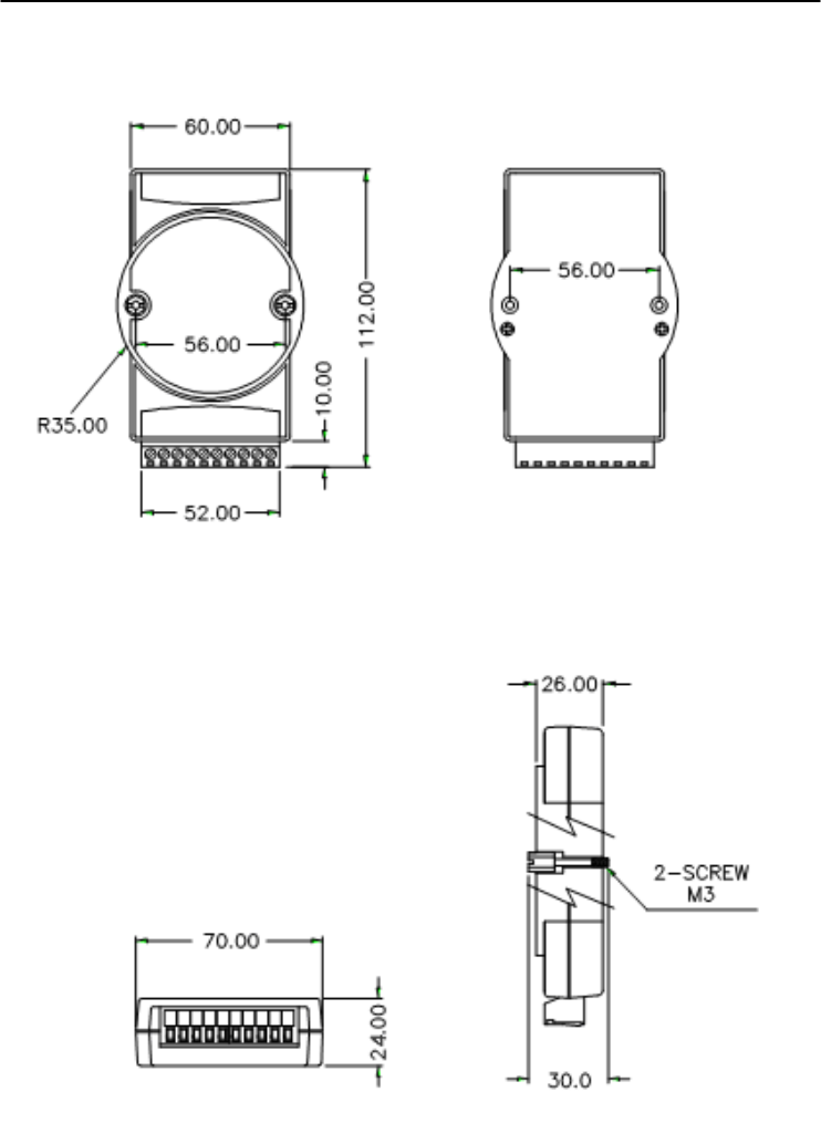
Technical Diagrams
C-
2
ADAM 4000 Series User’s Manual
C.1 ADAM Dimensions
Figure C-1 ADAM Modules Dimensions
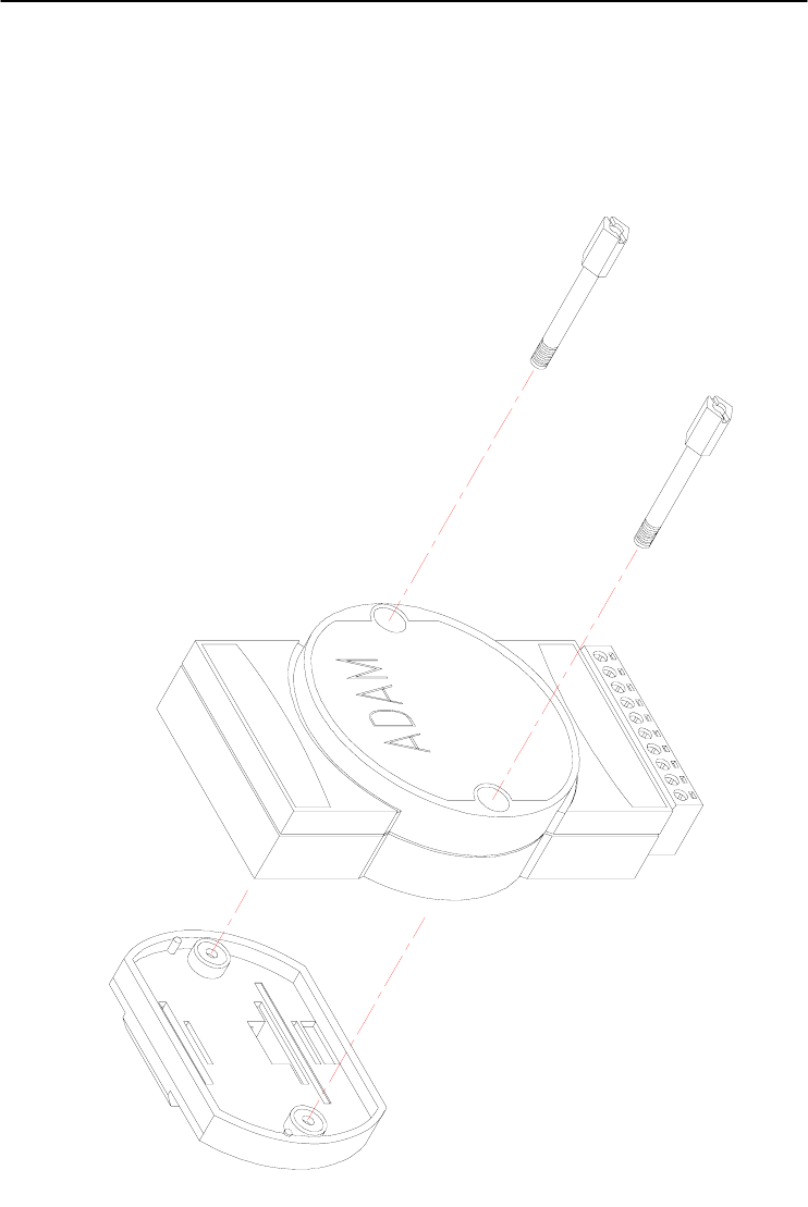
Appendix C
Appendix C Technical Diagrams C
-3
C.2 Installation
C.2.1 DIN-Rail Mounting
Figure C-2 DIN-Rail Adapter
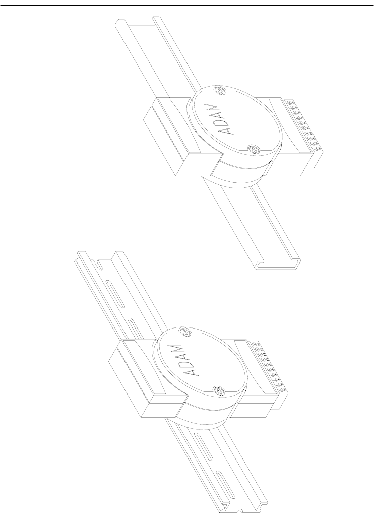
Technical Diagrams
C-
4
ADAM 4000 Series User’s Manual
Figure C-3 DIN-Rail Mounting
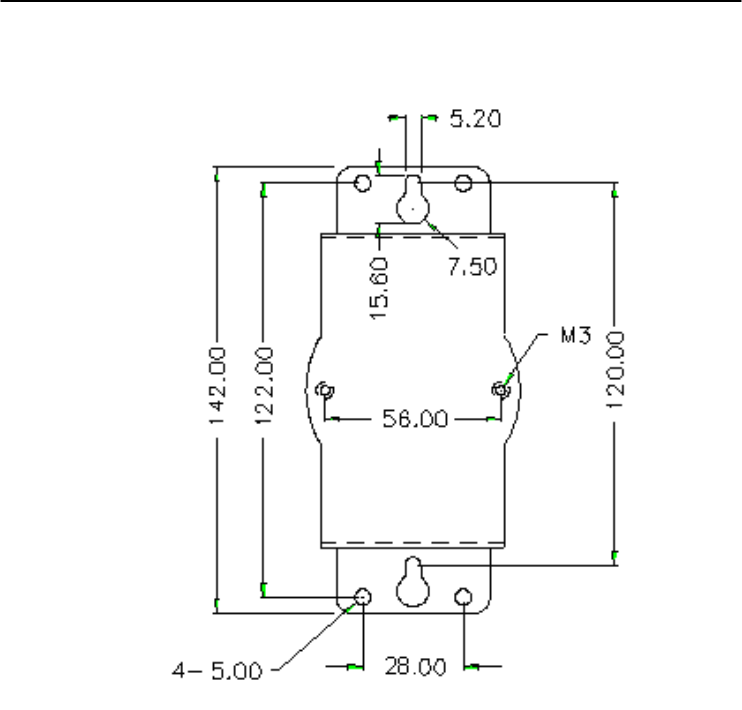
Appendix C
Appendix C Technical Diagrams C
-5
C.2.2 Panel Mounting
Figure C-4 Panel Mounting Bracket Dimensions
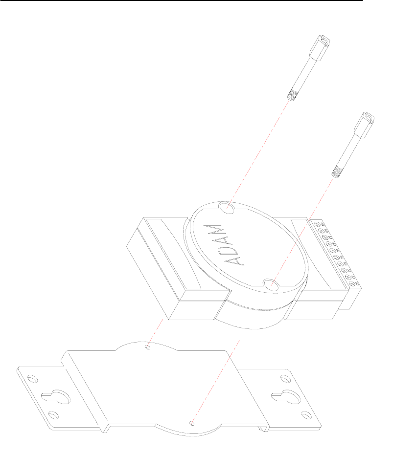
Technical Diagrams
C-
6
ADAM 4000 Series User’s Manual
Figure C-5 Panel Mounting
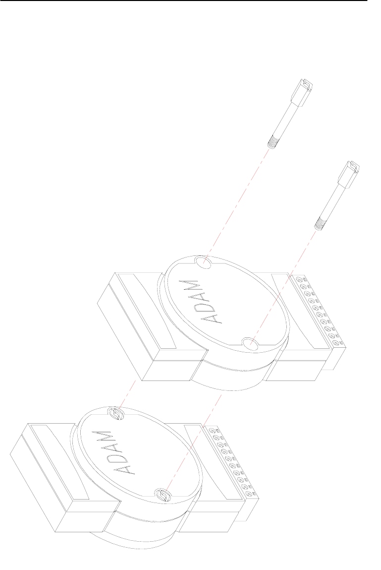
Appendix C
Appendix C Technical Diagrams C
-7
C.2.3 Piggyback Stack
Figure C-6 Piggyback Stack
Utility Software D
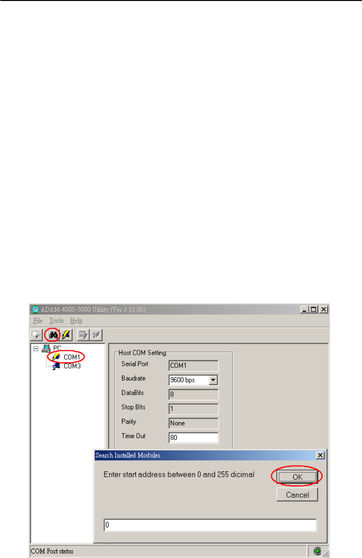
Utility Software
D-
2
ADAM 4000 Series User’s Manual
D.1 ADAM-4000 Utility Software
Together with the ADAM modules you will find a utility disk
containing utility software with the following capabilities:
- Module configuration
- Module calibration
- Data Input and Output
- Alarm settings
- Autoscan of connected modules
- Terminal emulation
The following text will give you a brief instruction how to use the
program.
Search the installed modules
The main screen consists of a menu bar at the top side of the screen and
a status field which displays information about the connected modules.
When the modules are connected well, you have to start the program
and search the modules by clicking the search icon as below. Please do
check the COM port and related settings are correct.
Figure D-1 Search screen
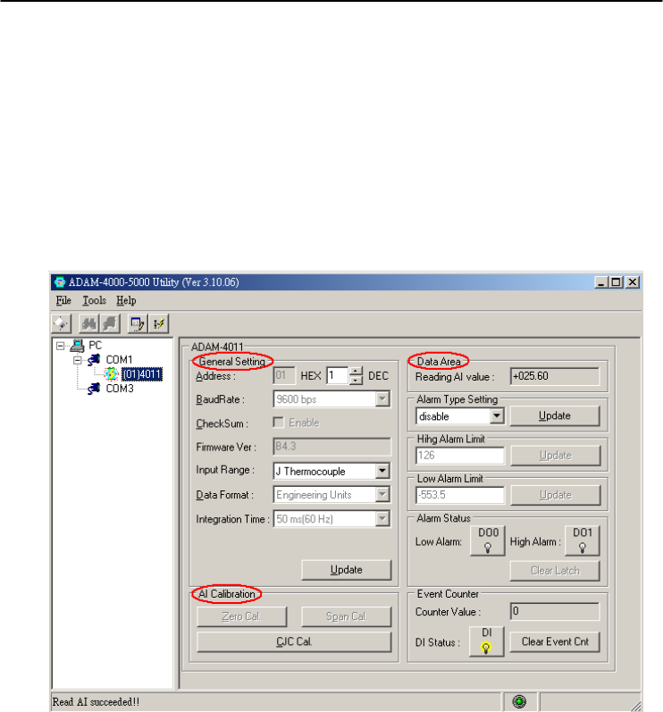
Appendix D
Appendix D Utility Software D
-3
NOTICE: When changing configuration, calibration or alarm
parameters, you should always make sure that a window appears
notifying you that the target module has confirmed the changes.
An asterix sign “*” before the modules address indicates that the
module is in the INIT* state
Configuration
Click the searched module, which you would like to configure. You
will find Setup page and related settings. An example is shown in
Figure D-2 for an ADAM-4011 module.
Figure D-2 Configuration Screen
Here there are three major areas, General Setting, Data Area and AI
Calibration. You may change the settings by selecting the preferred
items and then clicking Update button.
The Checksum and Baud rate options need special attention since they
can only be changed when an ADAM module is in the INIT* state. To
place a module in INIT state, its INIT terminal should be connected to
its GND terminal (see Baud rate and Checksum in Chapter 2). When
the ADAM module is not in INIT mode, an error message will appear.
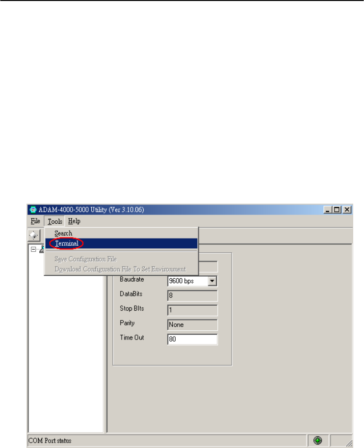
Utility Software
D-
4
ADAM 4000 Series User’s Manual
After you have made all necessary changes to the module configuration,
the utility will display the process data automatically.
Calibration
Please note only analog input and output modules can be calibrated. For
example, ADAM-4011 module has Zero, Span and CJC Calibration
items. To learn what steps should be taken to calibrate both input and
output modules, please refer to Chapter 8 Calibration.
Terminal Function
When you would like to send and receive commands on the RS-485
line directly, you can use this Terminal function in this utility.
Figure D-3 Terminal Function
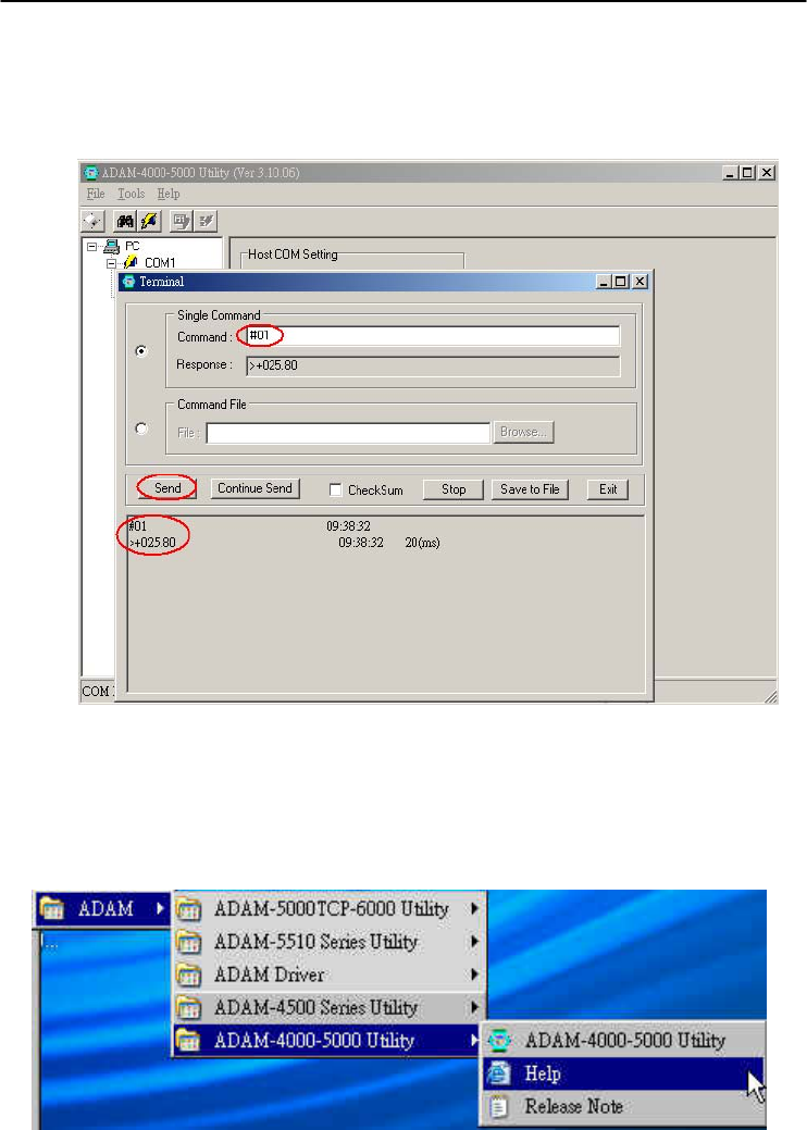
Appendix D
Appendix D Utility Software D
-5
You can type the ADAM ASCII command in the text box and click
Send button for testing the commands which are listed in Chapter 4
Command Set.
Figure D-4 Terminal Function
Notice: User can refer our help file to see more details for explanation of
Utility operation.
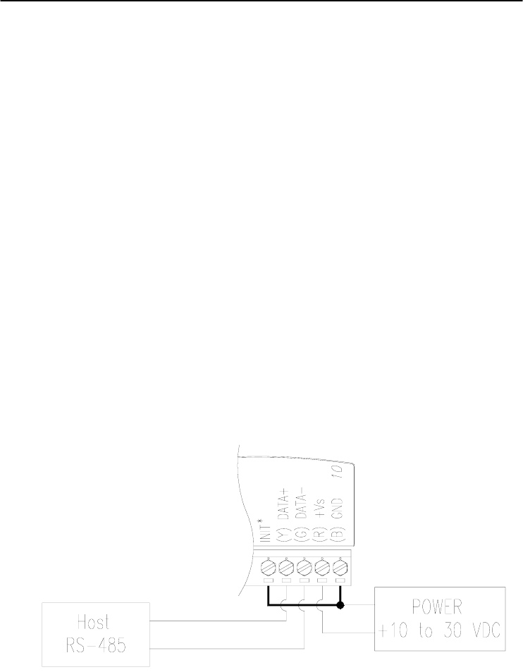
Utility Software
D-
6
ADAM 4000 Series User’s Manual
D.2 The procedure for ADAM-4000 series installation guide
When user first time gets ADAM-4000 modules, he can refer following
procedure to configure and operate. Especially note that new ADAM-4000
modules will have default factory settings with Address setting 1, and data
format 9600, N, 8, 1. Redefine the address to avoid ID conflict if two or
more new modules are used in the same network.
Standard Installation Procedures
1. Prepare the install environment
• Host computer
• Isolated RS-232/RS-485 Converter
• ADAM module
2. Install ADAM-4000-5000 utility in host computer
3. Wiring for ADAM-4000 module
Power supply & Communication Wiring
4. Move hardware switch to Initial mode (For some older Adam models,
use an external wire to connect the INIT* terminal to the GND
terminal. Booting the module while connecting the INIT* terminal with
the module’s GND terminal forces the configuration into a known state
called the INIT* state.)
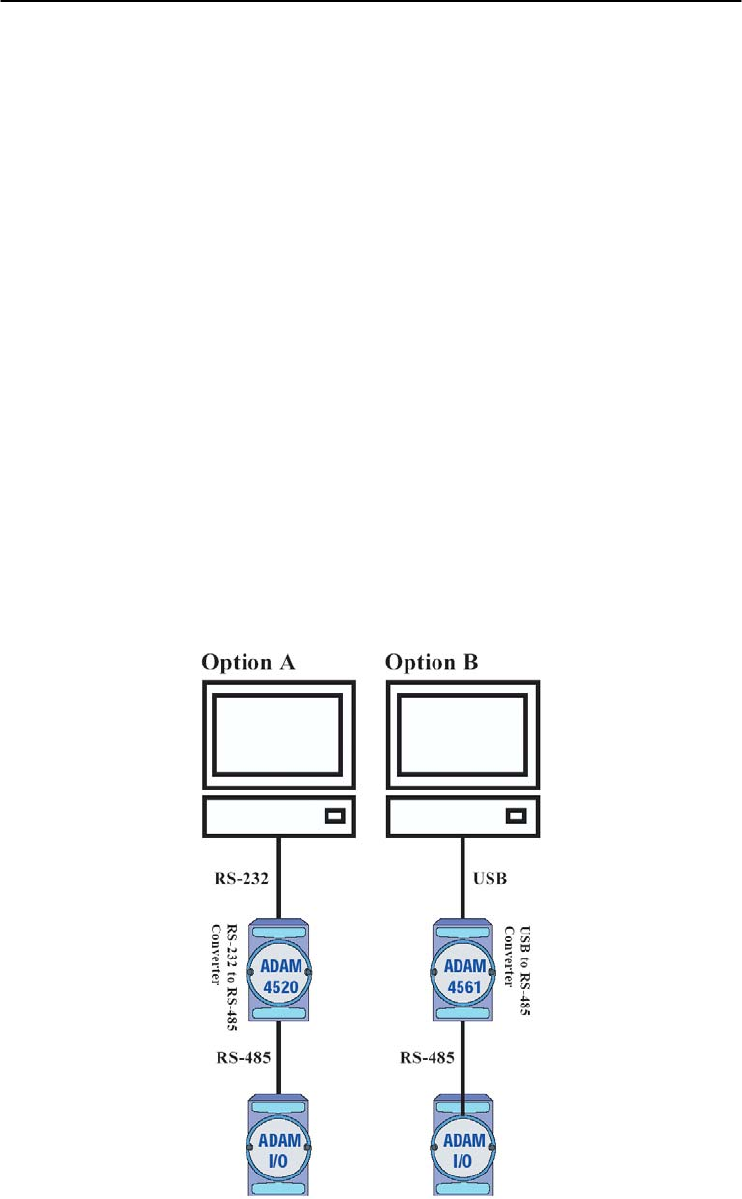
Appendix D
Appendix D Utility Software D
-7
INIT* state defaults:
Baud rate: 9600
Address: 00h
Checksum: disabled
Forcing the module in INIT* state does not change any parameters in the
module’s EEPROM. When the module is in the INIT* state with its INIT*
and GND terminals shorted, all configuration settings can be changed, and
the module will respond to all other commands normally.
Notice:
Init Mode
When the switch is set to the initial mode, the module will operate
with its factory settings. (Address 0 with data format 9600, N, 8, 1).
Normal Mode
When the switch is set to the normal mode, the module will operate
with user-defined settings. A power reset will not alter these settings.
5. Connect computer to the ADAM I/O module using a RS-232 to RS-485,
or USB to RS-485 converter.

Utility Software
D-
8
ADAM 4000 Series User’s Manual
6. Use software to configure settings
According to user’s application to set parameter like as address, baudrate,
data format, checksum, protocol…and so on.
Changing Baud rate and Checksum
Refer to Chapter 2 section 2.3.
Changing the protocol from ADAM ASCII to Modbus
Some ADAM-4000 modules support both ADAM ASCII and Modbus
protocols, and the factory default setting of these modules is ADAM
ASCII protocol. If you would like to configure the modules to Modbus
protocol, please refer to Appendix H which describes how to change the
protocol in ADAM utility.
7. Save changes and reset power on ADAM module for settings to take
effect.
RS-485 Network E

RS-485 Network
E-
2
ADAM 4000 Series User’s Manual
EIA RS-485 is industry’s most widely used bidirectional, balanced
transmission line standard. It is specifically developed for industrial
multi-drop systems that should be able to transmit and receive data at
high rates or over long distances.
The specifications of the EIA RS-485 protocol are as follows:
-Max line length per segment: 1200 meters (4000 feet)
-Throughput of 10 Mbaud and beyond
-Differential transmission (balanced lines) with high resistance against
noise
-Maximum 32 nodes per segment
-Bi-directional master-slave communication over a single set of twisted
pair cables
-Parallel connected nodes, true multi-drop
ADAM modules are fully isolated and use just a single set of twisted
pair wires to send and receive! Since the nodes are connected in
parallel they can be freely disconnected from the host without affecting
the functioning of the remaining nodes. In industry shielded twisted
pair is preferable due to the high noise ratio of the environment.
When nodes communicate through the network, no sending conflicts
can occur since a simple command/response sequence is used. There is
always one initiator (with no address) and many slaves (with address).
In this case the master is a personal computer that is connected with its
serial, RS-232, port to an ADAM RS-232/RS-485 converter. The slaves
are the ADAM I/O modules. When modules are not transmitting data,
they are in listen mode. The host computer initiates a
command/response sequence with one of the modules. Commands
normally contain the address of the module the host wants to
communicate with. The module with the matching address carries out
the command and sends its response to the host.
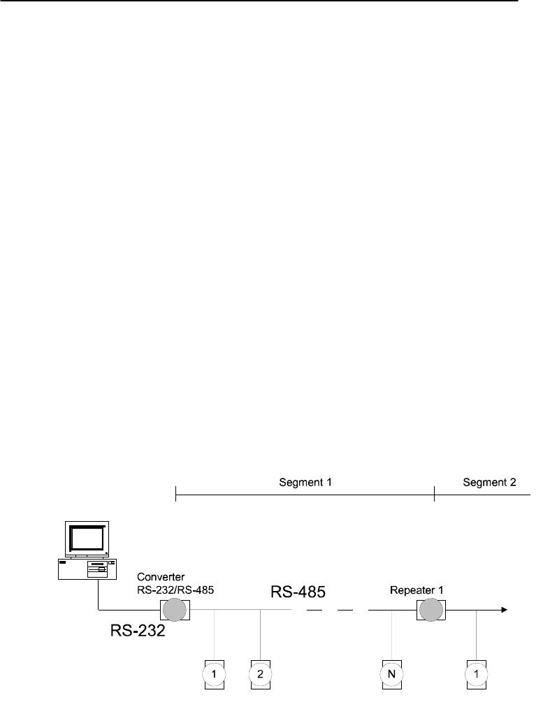
Appendix E
Appendix E RS-485 Network E
-3
E.1 Basic Network Layout
Multi-drop RS-485 implies that there are two main wires in an segment.
The connected modules tap from these two lines with so called drop
cables. Thus all connections are parallel and connecting or
disconnecting of a node doesn’t affect the network as a whole. Since
ADAM modules use the RS-485 standard, and use an ASCII-based
commands set, they can connect and communicate with all ASCII-
based computers and terminals. The basic layouts that can be used for
an RS-485 network are:
Daisychain
The last module of a segment is a repeater. It is directly connected to
the main-wires thereby ending the first segment and starting the next
segment. Up to 32 addressable modules can be diasychained. This
limitation is a physical one. When using more modules per segment the
IC driver current rapidly decreases, causing communication errors.
Totally the network can hold up to 256 addressable modules. The
limitation for this number is the two number hexadecimal address codes
that know 256 combinations. The ADAM converter, ADAM repeaters
and the host computer are non addressable units and therefore are not
included in these numbers.
Figure E-1 Daisychaining
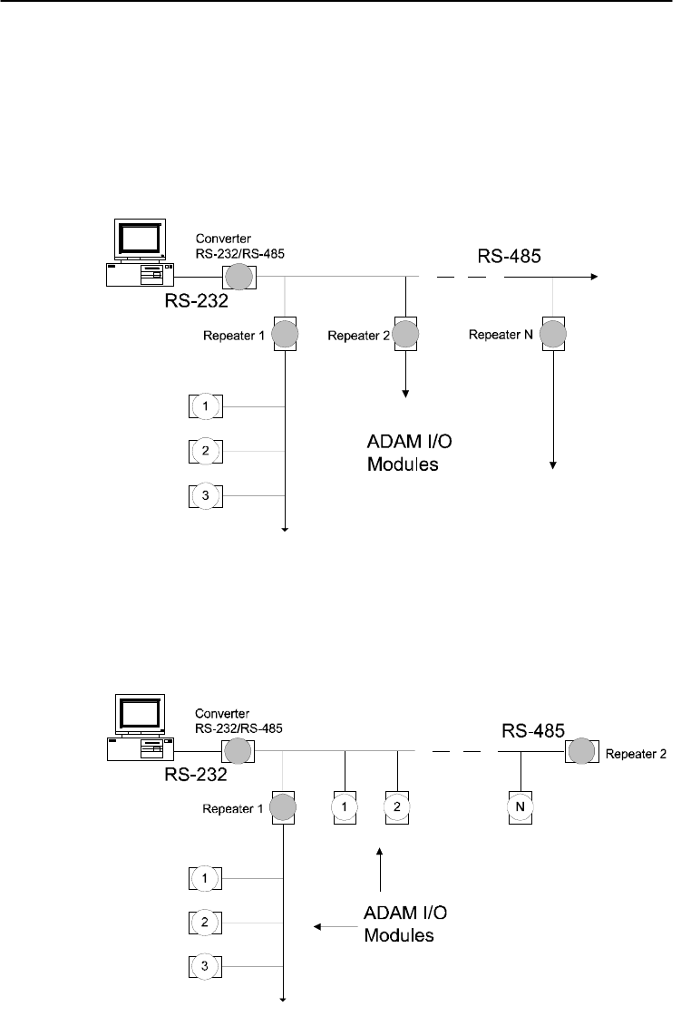
RS-485 Network
E-
4
ADAM 4000 Series User’s Manual
Star Layout
In this scheme the repeaters are connected to drop-down cables from
the main wires of the first segment. A tree structure is the result. This
scheme is not recommended when using long lines since it will cause a
serious amount of signal distortion due to a signal reflection in a several
line endings.
Figure E-2 Star Structure
Random
This is a combination of daisychain and hierarchical structure
Figure E-3 Random Structure
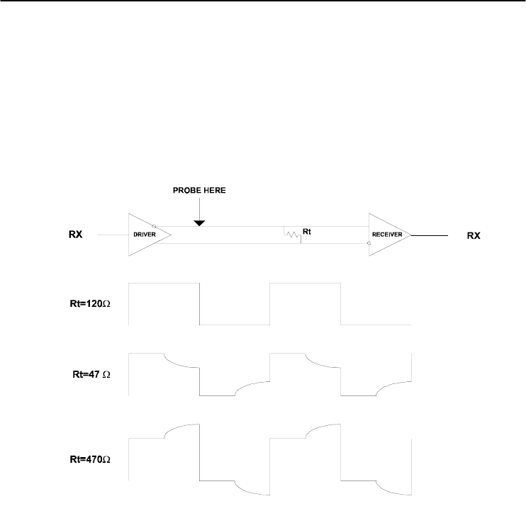
Appendix E
Appendix E RS-485 Network E
-5
E. 2 Line Termination
Each discontinuity in impedance causes reflections and distortion.
When an impedance discontinuity occurs in the transmission line the
immediate effect is signal reflection. This will lead to signal distortion.
Specially at line ends this mismatch causes problems. To eliminate this
discontinuity terminate the line with a resistor.
Figure E-4 Signal Distortion
The value of the resistor should be a close as possible to the
characteristic impedance of the line. Although receiver devices add
some resistance to the whole of the transmission line, normally it is
sufficient to the resistor impedance should equal the characteristic
impedance of the line.
Example:
Each input of the receivers has a nominal input impedance of 18 kW
feeding into a diode transistor- resistor biasing network that is
equivalent to an 18 kΩ input resistor tied to a common mode voltage of
2.4 V. It is this configuration which provides the large common range
of the receiver required for RS-485 systems! (See Figure E-5 below)
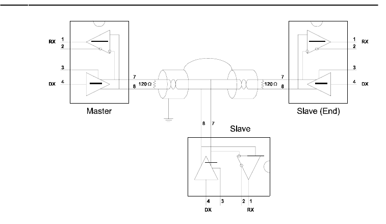
RS-485 Network
E-
6
ADAM 4000 Series User’s Manual
Figure E-5 Termination resistor locations
Because each input is biased to 2.4 V, the nominal common mode
voltage of balanced RS-485 systems, the 18 kΩ on the input can be
taken as being in series across the input of each individual receiver.
If thirty of these receivers are put closely together at the end of the
transmission line, they will tend to react as thirty 36kΩ resistors in
parallel with the termination resistor. The overall effective resistance
will need to be close to the characteristics of the line.
The effective parallel receiver resistance RP will therefore be equal to:
RP = 36 x 103/30 = 1200 W
While the termination receptor RT will equal:
RT = RO / [1 - RO/RP]
Thus for a line with a characteristic impedance of 100 Ω resistor, the
termination resistor RT should be:
RT = 100/[1 - 100/1200] = 110 Ω
Since this value lies within 10% of the line characteristic impedance.
Thus as already stated above the line termination resistor RT will
normally equal the characteristic impedance ZO.
The star connection causes a multitude of these discontinuities since
there are several transmission lines and is therefore not recommend.
NOTICE: The recommended wiring method that causes a minimum
amount of reflection is daisy chaining where all receivers tap from
one transmission line and needs to be terminated only twice.
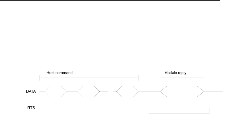
Appendix E
Appendix E RS-485 Network E
-7
E.3 RS-485 Data Flow Control
The RS-485 standard uses a single pair of wires to send and receive
data. This line sharing requires some method to control the direction of
the data flow. RTS (Request To Sent) and CTS (Clear To Sent) are the
most commonly used method.
Figure E-6 RS-485 data flow control with RTS
Intelligent RS-485 Control
ADAM-4510 and ADAM-4520 are both equipped with an I/O circuit
which can automatically sense the direction of the data flow. No
handshaking with the host (like RTS, Request to Send) is necessary to
receive data and forward it in the correct direction. You can use any
software written for half-duplex RS-232 with an ADAM network
without modification. The RS-485 control is completely transparent to
the user.
How to use the Checksum feature F

How to use the Checksum feature
F-
2
ADAM 4000 Series User’s Manual
A checksum helps you detect communication errors between the host
and module. This feature adds two extra checksum characters to the
command or response string; therefore, it reduces the throughput.
F.1 Checksum Enable/Disable
In order to enable configuration of a module’s checksum feature, its
INIT* terminal should be shorted to its GND terminal. Then, the
module should be rebooted. The checksum feature is enabled by setting
bit 6 of the data format/checksum parameter to 1. On the other hand,
the checksum is disabled by setting the parameter to 0. Whenever the
checksum feature is used, all the connected devices including the host
computer should be in enable mode.
The checksum is represented by a 2-character ASCII hexadecimal
format and is transmitted just prior to the carriage return. The checksum
equals to the result after performing modulus-256 (100h) of all the
ASCII values’ sum preceding the checksum. If the checksum is missing
or incorrect, the module will not respond.
Example 1
The following example is an Analog Data In command and response
when the checksum is enabled:
Command: #0588(CR)
Response: +3.56719D(CR)
The input value of the module at address 05h is +3.5671 V. (The data
format is in engineering units.) The command checksum (88h) is the
sum of the ASCII values for the following characters: #, 0, and 5. The
response checksum (9Dh) is the sum of the ASCII values for the
following characters: “>”, “+”, “3”, “.”, “5”, “6”, “7”, and “1”.

Appendix F
Appendix F How to use the Checksum feature F
-3
Example 2
This example explains how to calculate the checksum value of a Read
High alarm limit command string:
Case 1. (If the Checksum feature is disabled)
Command: $07RH(cr)
Response: !07+2.0500(cr) when the command is valid.
Case 2. (If the Checksum feature is enabled)
Command: $07RH25(cr)
Response: !07+2.0500D8(cr)
where:
25 represents the checksum of this command, and
D8 represents the checksum of the response.
The checksum of the command string is derived as shown below:
25h = (24h+ 30h + 37h + 52h + 48h) MOD 100h
The hexadecimal ASCII codes for $, 0, 7, R, H are 24h, 30h, 37h, 52h
and 48h respectively. The sum of these ASCII codes is 125h, and the
result equals to 25h after modulus-256(100h) execution.

How to use the Checksum feature
F-
4
ADAM 4000 Series User’s Manual
Table F-1 Printable ASCII Characters
HEX ASCII HEX ASCII HEX ASCII HEX ASCII
21 ! 40 @ 5F _ 7E ~
22 "" 41 A 60 '
23 # 42 B 61 a
24 $ 43 C 62 b
25 % 44 D 63 c
26 & 45 E 64 d
27 ' 46 F 65 e
28 ( 47 G 66 f
29 ) 48 H 67 g
2A * 49 I 68 h
2B + 4A J 69 i
2C , 4B K 6A j
2D - 4C L 6B k
2E . 4D M 6C l
2F / 4E N 6D m
30 0 4F O 6E n
31 1 50 P 6F o
32 2 51 Q 70 p
33 3 52 R 71 q
34 4 53 S 72 r
35 5 54 T 73 s
36 6 55 U 74 t
37 7 56 V 75 u
38 8 57 W 76 v
39 9 58 X 77 w
3A : 59 Y 78 x
3B ; 5A Z 79 y
3C < 5B [ 7A z
3D = 5C \ 7B {
3E > 5D ] 7C |
3F ? 5E ^ 7D }
ADAM-4000 I/O Modbus Mapping Table G

ADAM-4000 I/O Modbus Mapping Table
G-
2
ADAM 4000 Series User’s Manual
The model list of ADAM-4000 I/O series support Modbus
protocol
Model Description
1
ADAM-4015 6-channel RTD Input Module
ADAM-4015T 6-channel Thermistor Input Module
2 ADAM-4017+ 8-channel Analog Input Module
3 ADAM-4018+ 8-channel Thermocouple Input Module
4 ADAM-4019+ 8-Channels Universal Analog Input Module
5 ADAM-4024 4-channel Analog Output Module
6 ADAM-4051 16-channel Isolated Digital Input with LED
Module
7 ADAM-4055 16-channel Isolated Digital I/O with LED
Module
8 ADAM-4056S 12 channel Sink-type Isolated Digital Output
Module
9 ADAM-4056SO 12 channel Source-type Isolated Digital
Output Module
10 ADAM-4068 8 Relay Output Module
11 ADAM-4069 8 Power Relay Output Module

Appendix G
Appendix G ADAM-4000 I/O Modbus Mapping Table G-
3
1. ADAM-4015 6-channel RTD Input Module and
ADAM-4015T 6-channel Thermistor Input Module
ADDR 0X Channel Item Attribute Memo
00201 0 Burn-out Signal R 1:Burn-out
00202 1 Burn-out Signal R
00203 2 Burn-out Signal R
00204 3 Burn-out Signal R
00205 4 Burn-out Signal R
00206 5 Burn-out Signal R
00207 6 Burn-out Signal R
00208 7 Burn-out Signal R
ADDR 4X Channel Item Attribute Memo
40001 0 Current Value R
40002 1 Current Value R
40003 2 Current Value R
40004 3 Current Value R
40005 4 Current Value R
40006 5 Current Value R
40007 6 Current Value R
40008 7 Current Value R
40201 0 Type Code R/W 0x00 0x0e
40202 1 Type Code R/W
40203 2 Type Code R/W
40204 3 Type Code R/W
40205 4 Type Code R/W
40206 5 Type Code R/W
40207 6 Type Code R/W
40208 7 Type Code R/W
40211 Module Name 1 R 0x40 0x18
40212 Module Name 2 R 0x50 0x00
40213 Version 1 R 0xa2 0x00
40214 Version 2 R 0x00 0x00
40221 Channel Enable R/W 0x00 0xff

ADAM-4000 I/O Modbus Mapping Table
G-
4
ADAM 4000 Series User’s Manual
2. ADAM-4018+ 8-channel Thermocouple Input Module
ADDR 0X Channel Item Attribute Memo
00201 0 Burn-out Signal R 1:Burn-out
00202 1 Burn-out Signal R
00203 2 Burn-out Signal R
00204 3 Burn-out Signal R
00205 4 Burn-out Signal R
00206 5 Burn-out Signal R
00207 6 Burn-out Signal R
00208 7 Burn-out Signal R
ADDR 4X Channel Item Attribute Memo
40001 0 Current Value R
40002 1 Current Value R
40003 2 Current Value R
40004 3 Current Value R
40005 4 Current Value R
40006 5 Current Value R
40007 6 Current Value R
40008 7 Current Value R
40201 0 Type Code R/W 0x00 0x0e
40202 1 Type Code R/W
40203 2 Type Code R/W
40204 3 Type Code R/W
40205 4 Type Code R/W
40206 5 Type Code R/W
40207 6 Type Code R/W
40208 7 Type Code R/W
40211 Module Name 1 R 0x40 0x18
40212 Module Name 2 R 0x50 0x00
40213 Version 1 R 0xa2 0x00
40214 Version 2 R 0x00 0x00
40221 Channel Enable R/W 0x00 0xff

Appendix G
Appendix G ADAM-4000 I/O Modbus Mapping Table G-
5
3. ADAM-4017+ 8-channel Analog Input Module
ADDR 4X Channel Item Attribute Memo
40001 0 Current Value R
40002 1 Current Value R
40003 2 Current Value R
40004 3 Current Value R
40005 4 Current Value R
40006 5 Current Value R
40007 6 Current Value R
40008 7 Current Value R
40201 0 Type Code R/W
40202 1 Type Code R/W
40203 2 Type Code R/W
40204 3 Type Code R/W
40205 4 Type Code R/W
40206 5 Type Code R/W
40207 6 Type Code R/W
40208 7 Type Code R/W
40211 Module Name 1 R 0x40 0x17
40212 Module Name 2 R 0x50 0x00
40213 Version 1 R 0xa2 0x00
40214 Version 2 R 0x00 0x00
40221 Channel Enable R/W 0x00 0xff
ADAM-4000 I/O Modbus Mapping Table
G-
6
ADAM 4000 Series User’s Manual
4. ADAM-4019+ 8-Channels Universal Analog Input Module
ADDR 0X Channel Item Attribute Memo
00201 0 Burn-out Signal R
0: Non
1:Burn-out
00202 1 Burn-out Signal R
00203 2 Burn-out Signal R
00204 3 Burn-out Signal R
00205 4 Burn-out Signal R
00206 5 Burn-out Signal R
00207 6 Burn-out Signal R
00208 7 Burn-out Signal R
ADDR 4X Channel Item Attribute Memo
40001 0 Current Value R
40002 1 Current Value R
40003 2 Current Value R
40004 3 Current Value R
40005 4 Current Value R
40006 5 Current Value R
40007 6 Current Value R
40008 7 Current Value R
40201 0 Type Code R/W
40202 1 Type Code R/W
40203 2 Type Code R/W
40204 3 Type Code R/W
40205 4 Type Code R/W
40206 5 Type Code R/W
40207 6 Type Code R/W
40208 7 Type Code R/W
40211 Module Name 1 R 0x40 0x19
40212 Module Name 2 R 0x42 0x00
40213 Version 1 R 0xa1 0x00
40214 Version 2 R 0x00 0x00
40221 Channel Enable R/W 0x00 0xff
Appendix G
Appendix G ADAM-4000 I/O Modbus Mapping Table G-
7
5. ADAM-4024 4-channel Analog Output Module
ADDR 0X Channel Item Attribute Memo
00001 0 Emergency DI Input Flag R
00002 1 Emergency DI Input Flag R
00003 2 Emergency DI Input Flag R
00004 3 Emergency DI Input Flag R
ADDR 4X Channel Item Attribute Memo
40001 0 Current Output Value R/W
40002 1 Current Output Value R/W
40003 2 Current Output Value R/W
40004 3 Current Output Value R/W
40201 0 Type Code R/W
40202 1 Type Code R/W
40203 2 Type Code R/W
40204 3 Type Code R/W
40211 Module Name 1 R 0x40 0x24
40212 Module Name 2 R 0x00 0x00
40213 Version 1 R 0xa2 0x00
40214 Version 2 R 0x00 0x00
40215 Comm Safety Enable R Enable:0x00 0x01
40216 Comm Safety Flag R Occur:0x00 0x01
40221 Channel Enable R/W 0x00 0xff
ADAM-4000 I/O Modbus Mapping Table
G-
8
ADAM 4000 Series User’s Manual
6. ADAM-4051 16-channel Isolated Digital Input with LED
Module
ADDR 0X Channel Item Attribute Memo
00001 0 DI Input Signal R
00002 1 DI Input Signal R
00003 2 DI Input Signal R
00004 3 DI Input Signal R
00005 4 DI Input Signal R
00006 5 DI Input Signal R
00007 6 DI Input Signal R
00008 7 DI Input Signal R
00009 8 DI Input Signal R
00010 9 DI Input Signal R
00011 10 DI Input Signal R
00012 11 DI Input Signal R
00013 12 DI Input Signal R
00014 13 DI Input Signal R
00015 14 DI Input Signal R
00016 15 DI Input Signal R
ADDR 4X Channel Item Attribute Memo
40001 0 Current Output Value R/W
40002 1 Current Output Value R/W
40003 2 Current Output Value R/W
40004 3 Current Output Value R/W

Appendix G
Appendix G ADAM-4000 I/O Modbus Mapping Table G-
9
7. ADAM-4055 16-channel Isolated Digital I/O with LED
Module
ADDR 0X Channel Item Attribute Memo
00001 0 DI Input Signal R
00002 1 DI Input Signal R
00003 2 DI Input Signal R
00004 3 DI Input Signal R
00005 4 DI Input Signal R
00006 5 DI Input Signal R
00007 6 DI Input Signal R
00008 7 DI Input Signal R
00017 0 DO Output Value R/W
00018 1 DO Output Value R/W
00019 2 DO Output Value R/W
00020 3 DO Output Value R/W
00021 4 DO Output Value R/W
00022 5 DO Output Value R/W
00023 6 DO Output Value R/W
00024 7 DO Output Value R/W
ADDR 4X Channel Item Attribute Memo
40211 Module Name 1 R 0x40 0x55
40212 Module Name 2 R 0x00 0x00
40213 Version 1 R 0xa2 0x00
40214 Version 2 R 0x00 0x00
40215 Comm Safety Enable R Enable:0x00
0x01
40216 Comm Safety Flag R Occur:0x00 0x01

ADAM-4000 I/O Modbus Mapping Table
G-
10
ADAM 4000 Series User’s Manual
8. ADAM-4056S 12 channel Sink-type Isolated Digital Output
Module
ADDR 0X Channel Item Attribute Memo
00017 0 Digital Output Value R/W
00018 1 Digital Output Value R/W
00019 2 Digital Output Value R/W
00020 3 Digital Output Value R/W
00021 4 Digital Output Value R/W
00022 5 Digital Output Value R/W
00023 6 Digital Output Value R/W
00024 7 Digital Output Value R/W
00025 8 Digital Output Value R/W
00026 9 Digital Output Value R/W
00027 10 Digital Output Value R/W
00028 11 Digital Output Value R/W
ADDR 4X Channel Item Attribute Memo
40211 Module Name 1 R 0x40 0x56
40212 Module Name 2 R 0x53 0x00
40213 Version 1 R 0xA1 0x00
40214 Version 2 R 0x00 0x00
40215 Comm Safety Enable R Enable:0x00 0x01
40216 Comm Safety Flag R Occur: 0x00 0x01

Appendix G
Appendix G ADAM-4000 I/O Modbus Mapping Table G-
11
9. ADAM-4056SO 12 channel Source-type Isolated Digital Output
Module
ADDR 0X Channel Item Attribute Memo
00017 0 Digital Output Value R/W
00018 1 Digital Output Value R/W
00019 2 Digital Output Value R/W
00020 3 Digital Output Value R/W
00021 4 Digital Output Value R/W
00022 5 Digital Output Value R/W
00023 6 Digital Output Value R/W
00024 7 Digital Output Value R/W
00025 8 Digital Output Value R/W
00026 9 Digital Output Value R/W
00027 10 Digital Output Value R/W
00028 11 Digital Output Value R/W
00029 Over Current CH0-3 Over Current Flag R/W
00030 Over Current CH4-7 Over Current Flag R/W
00031 Over Current CH8-11 Over Current Flag R/W
ADDR 4X Channel Item Attribute Memo
40211 Module Name 1 R 0x40 0x56
40212 Module Name 2 R 0x53 0x4F
40213 Versoin 1 R 0xA1 0x00
40214 Versoin 2 R 0x00 0x00
40215 Comm Safety Enable R Enable:0x00 0x01
40216 Comm Safety Flag R Occur: 0x00 0x01
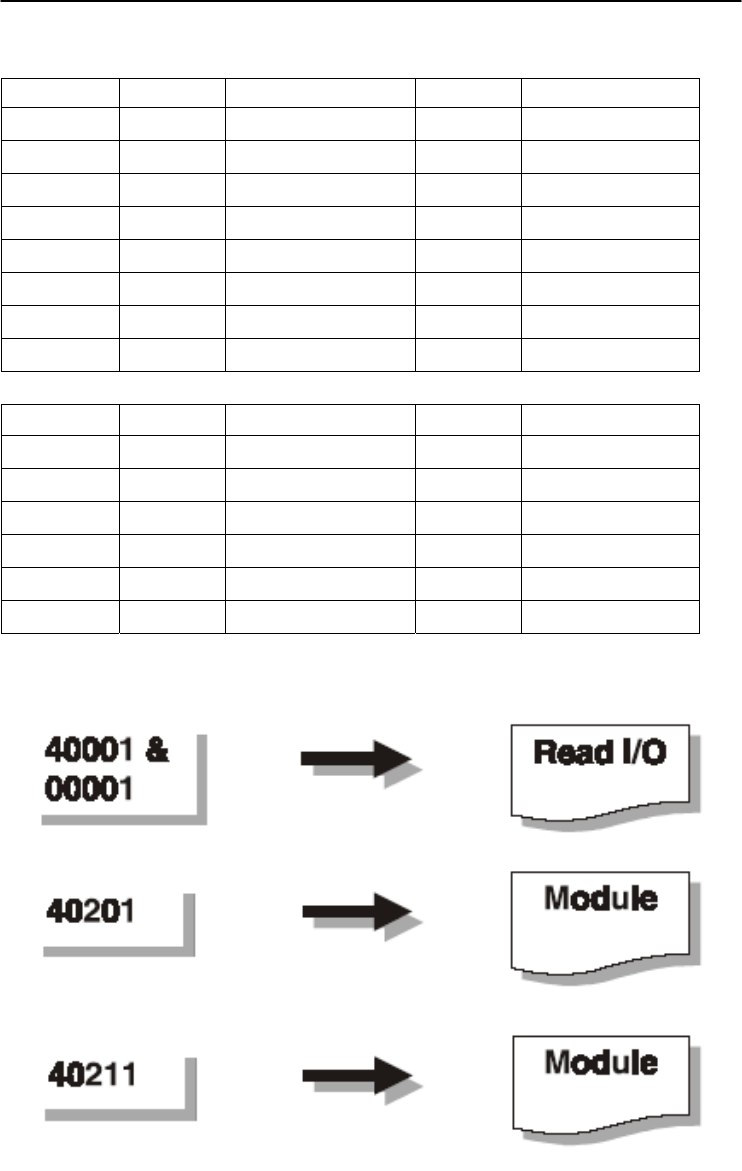
ADAM-4000 I/O Modbus Mapping Table
G-
12
ADAM 4000 Series User’s Manual
10. ADAM-4068 8 Relay Output Module
ADDR 0X Channel Item Attribute Memo
00017 0 Relay Output Value R/W
00018 1 Relay Output Value R/W
00019 2 Relay Output Value R/W
00020 3 Relay Output Value R/W
00021 4 Relay Output Value R/W
00022 5 Relay Output Value R/W
00023 6 Relay Output Value R/W
00024 7 Relay Output Value R/W
ADDR 4X Channel Item Attribute Memo
40211 Module Name 1 R 0x40 0x68
40212 Module Name 2 R 0x00 0x00
40213 Version 1 R 0xa2 0x00
40214 Version 2 R 0x00 0x00
40215 Comm Safety Enable R Enable:0x00 0x01
40216 Comm Safety Flag R Occur:0x00 0x01
Appendix G
Appendix G ADAM-4000 I/O Modbus Mapping Table G-
13
11. ADAM-4069 8 Power Relay Output Module
ADDR 0X Channel Item Attribute Memo
00017 0 Relay Output Value R/W
00018 1 Relay Output Value R/W
00019 2 Relay Output Value R/W
00020 3 Relay Output Value R/W
00021 4 Relay Output Value R/W
00022 5 Relay Output Value R/W
00023 6 Relay Output Value R/W
00024 7 Relay Output Value R/W
ADDR 4X Channel Item Attribute Memo
40211 Module Name 1 R 0x40 0x69
40212 Module Name 2 R 0x00 0x00
40213 Version 1 R 0xa1 0x01
40214 Version 2 R 0x00 0x00
40215 Comm Safety Enable R Enable:0x00 0x01
40216 Comm Safety Flag R Occur:0x00 0x01
Changing Configuration to Modbus Protocol H

Changing Configuration to Modbus Protocol
H-
2
ADAM 4000 Series User’s Manual
The ADAM-4000 Modbus version modules may come from the
factory set for which ADAM ASCII protocol are set as the default
protocol.
If the module is connected to a Modbus network, the Modbus
network may not recognize the module. This may be caused by
the incorrect settings. ADAM-4000 module should be set-up for
Modbus protocol instead of ADAM ASCII protocol.
Please follow the steps as below for configuring an ADAM-4000
module to Modbus protocol.
1. Configure the ADAM-4000 Module with the ADAM-4000 utility
(latest ADAM-4000 utility can be found at www.advantech.com
service & support.)
2. Initialize the ADAM-4000 on a RS-485 network (the preferred
method is one module at a time on the RS-485 network).
3. With the module powered off, turn the switch in the “Init” position.
(For some older Adam models, use an external wire to connect the
INIT* terminal to the GND terminal)
4. Power up the module
5. Wait 10 seconds for the module to initialize.
6. Using the ADAM-4000 utility, search (scan) for the module to
change the protocol. (Initial COM settings: 9600 baud, N-8-1)
7. The utility will identify the module from the search function.
8. The ADAM-4000 utility will now permit the serial data protocol to
be changed to the Modbus protocol.
9. The address and COM port settings can also be changed at this time.
10. To access the module, click on the module icon in the utility.
11. Update the settings by pressing the “Update” button.
12. Power off the module.
13. Turn the switch back to NORMAL* position. (For the older Adam
models, remove the wire between the INIT* and GND terminals)
14. The module is now ready to be placed in the Modbus network.
