Aeon Labs FT132 Dual In-Way Switch User Manual 2
Aeon Labs LLC. Dual In-Way Switch 2
User Manual
View the expanded manual:
http://aeotec.com/support
Dual In-Wall Switch
IMPORTANT!
This product has been fully tested and certified to
work with Z-Wave by the Z-Wave Alliance. It is
crafted using Z-Wave Plus, the latest device version
of Z-Wave. As such, if the product does not work
with your gateway, please be sure to check with your
gateway manufacturer that they have integrated this
device with their gateway for full operation.
Aeotec by Aeon Labs In-Wall Switch.
Aeotec In-Wall Switch is a low-cost Z-Wave Switch
control (on/off) of any In-Wall Switches. It can report
immediate wattage consumption or kWh energy
usage over a period of time. In the event of power
failure, non-volatile memory retains all programmed
information relating to the unit’s operating status.
It can connect to 2 external manual switches to
control the load ON/OFF independently. Its surface
has a pin socket, which can be used for connecting
to the touch panel, so you can also use the touch
panel to control the In-Wall Switch.
The In-Wall Switch is also a security Z-Wave device
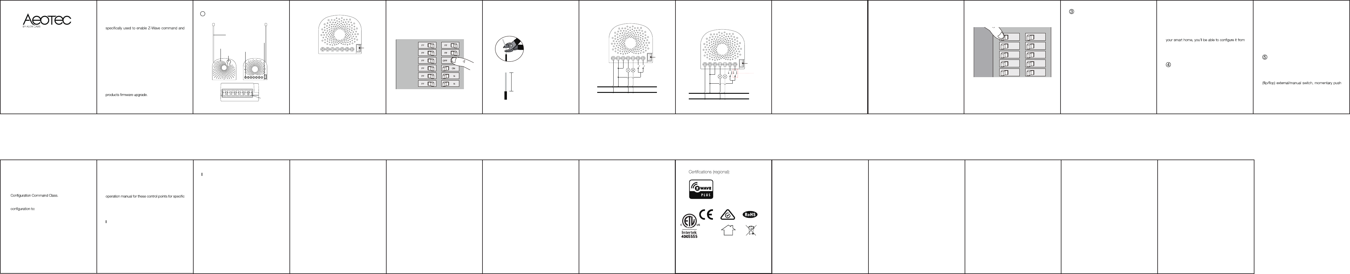
and supports Over The Air (OTA) feature for the
1
1
2
(Front)
Action Button
Touch panel connection port
RGB LED
RF antenna
Fastening screws
Familiarize yourself with your In-Wall
Switch.
2
(Back)
(Bottom)
Wire connection
port
Z-Wave and Z-Wave Plus are
registered trademarks of Sigma
Designs and its subsidiaries in the
United States and other countries
FCC ID: XBAFT132
21
3
N – Power input for neutral
L – Power input for live
IN – Input for load power supply
OUT1 – Output for load 1
OUT2 – Output for load 2
S1 – External switch control for load 1
S2 – External switch control for load 2
Notes for the wire connection ports:
IN S1 S2
OUT1 OUT2
Touch panel
L N
Preparing connection wires
14 AWG power wires for Input/ Output.
2.
IN S1 S2
OUT1 OUT2
Wiring diagram of AC120V power input.
LTouch
panel
Live
Neutral
AC120V
N
7
Wiring diagram of 3-Way connection.
N IN OUT1 OUT2 S1 S2 Touch
panel
Live
Neutral
AC120V
3-Way
Switch
(SPDT)
L
Live/Hot wire connection: Connect the Live/Hot
wire to the “L” terminal on the In-Wall Switch.
Neutral wire connection: Connect the Neutral
wire to the “N” terminal on the In-Wall Switch.
Load wire connection: Connect the 2 Load
wires to the “OUT1” and “OUT2” on the In-Wall
Switch.
External/manual Switch connection: Connect
2 18AWG wires to the “S1” and “S2” on the In-
Wall Switch.
External/manual Switch connection: Connect 2
18AWG wires form the In-Wall Switch to the 2
terminals on the External/manual Switch.
8
Install In-Wall Switch to the gang box.
3.
a.
b.
c.
d.
e.
Relative humidity: 8% to 80%.
Operating distance: Up to 492 feet/150 meters
outdoors.
6Technical specifications.
Reset your In-Wall Switch.
If at some stage, your primary controller is missing or
inoperable, you may wish to reset all of your In-Wall
Switch’s settings to their factory defaults. To do this,
press and hold the Action Button for 20 seconds
and then release it. Your In-Wall Switch will now be
reset to its original settings, and the green LED will
be solid for 2 seconds and then remain the colourful
17
Model:FT132-A,ZW132-A,FT140-A,ZW140-A
Power input: 120VAC , 60Hz.
Rated output: 6.5A /way
Total current: Max 10A.
Max standby power: 0.8W.
Operating temperature: 0℃ to 40℃/32℉to 104℉.
9
Mounting the gang box.4.
Position all wires to provide room for the
device. Place the In-Wall Switch inside the
gang box towards the back of the box.
Position the antenna towards the back of the
box, away from all other wiring.
Reinstall the In-Wall Switch to the gang box.
Reinstall the cover onto the gang box.
a.
b.
c.
d.
Set your Z-Wave Plus controller into pairing
mode.
Press the Action Button 2 times within 1 second
on the In-Wall Switch, the blue LED (secure
indication) will blink to indicate the In-Wall Switch
is entering into secure pairing mode.
If the In-Wall Switch has been successfully added
to your Z-Wave network, its RGB LED will be
solid. If the pairing was unsuccessful, the red
LED will be on for 2 seconds and then remain a
colourful gradient, repeat the instructions above
from step 1.
Including In-Wall Switch as a secure device:
In order to take full advantage of the Smart Film Hub,
you will want your In-Wall Switch as a security device
that uses encrypted messages to communicate in
your Z-wave network. A security enabled controller/
gateway (or Z-Wave Plus controller) is required.
1.
2.
3.
16
10
Restore Power.
Restore power at the circuit breaker or fuse.
5.
15
of the control points. (The specific Z-Wave
commands supporting energy monitoring are the
Meter Command Class. Automatic reports are
sent to association group 1, which is setup via the
Association Command Class.) Please consult the
instructions on monitoring the In-Wall Switch.
Security or Non-security feature of your In-
Wall Switch in Z-Wave network.
Including In-Wall Switch as a non-secure device:
If you want your In-Wall Switch as a non-secure
device in your Z-Wave network, press the Action
Button once on In-Wall Switch when you pair it to
your gateway. If inclusion is successful, the green
LED will be on for 2 seconds, and then return to a
solid indication (following the state of the Hub). If
inclusion is unsuccessful, the red LED will be on for
2 seconds and then return to a colourful gradient.
11
After your In-Wall Switch is installed and powered
on, you are now able to manually control the In-Wall
Switch to turn it On/Off directly via pressing your In-
Wall Switch’s Action Button, it is time to add your
In-Wall Switch to the Z-Wave network. To set your
Z-Wave gateway/controller into pairing mode, please
refer to the respective section within your controller
instruction manual.
3
Adding your In-Wall Switch to a Z-Wave
network.
Quick start.
Set your Z-Wave controller into pairing mode.
Press the Action Button on the In-Wall Switch,
the green LED (non-secure indication) will blink to
indicate the In-Wall Switch is entering into pairing
mode.
If the In-Wall Switch has been successfully added
1.
2.
3.
14
You can also set the external switch mode through
Parameter 120 [1 byte dec] is the parameter that
will set one of the 3 different modes. If you set this
(0) 2-state switch mode
(1) Momentary push button Mode
(2) 3-way switch mode
Monitoring Energy Consumption.
The Aeotec In-Wall Switch can report wattage
energy usage or kWh energy usage to a Z-Wave
control point when requested. If this function
is supported by the control points, the energy
consumption will be displayed in the user interface
on the manual switch once and wait 2 seconds
for the In-Wall Switch to detect the type of manual
switch.
12
5Advanced functions.
Changing mode on the External Switch/Button
Control.
The In-Wall Switch can be controlled via 2-state
button or the 3-way switch. To automatically detect
and set the mode to the appropriate type of manual
switch wired into In-Wall Switch, toggle the button
13
to your Z-Wave network, its RGB LED will be
solid. If the pairing was unsuccessful, the red
LED will be on for 2 seconds and then remain a
colourful gradient, repeat the instructions above
from step 1.
With your In-Wall Switch now working as a part of
your home control software/phone application.
Please refer to your software’s user guide for further
instructions on configuring In-Wall Switch to your
needs.
4Removing In-Wall Switch from a
Z-Wave network.
Your In-Wall Switch can be removed from your
Z-Wave network at any time. You’ll need to use
your Z-Wave network’s main controller. To set your
Z-Wave controller/gateway into removal mode,
please refer to the respective section within your
Set your Z-Wave controller into removal mode.
Press the Action Button on the In-Wall Switch.
If the In-Wall Switch has been successfully
removed from your Z-Wave network, its RGB
LED will remain colourful gradient. If the removal
was unsuccessful, the RGB LED will still be solid
(following the state of the output load), repeat the
instructions above from step 1.
1.
2.
3.
controller instruction manual.
Manufacturer :Fantem Technologies (Shenzhen) Co.,Ltd
IC Caution:
IC Note : Cet appareil est conforme à la Partie 15 des rè
glements de la FCC et aux normes RSS de
l’Industrie du Canada. Son fonctionnement est soumis aux
deux conditions suivantes : (1) cetappareil ne doit pas causer
des interférences nuisibles, et (2) cet appareil doit accepter
touteinterférence reçue, y compris les interférences qui
peuvent provoquer un fonctionnementindésirable.
Le fabricant n'est pas responsable des toutes interférences
radio ou télévision causées par des modifications non
autorisées apportées à cet appareil. De telles modifications
peuvent empêcher l’utilisateur d’utiliser l'appareil.
To maintain compliance with FCC’s RF exposure guidelines,
this equipment should be installed and operated with a
minimum distance of 20cm between the radiator and
your body.
le dispositif de a été évalués à répondre général rf
exposition exigence.pour maintenir la conformité avec les
directives d'exposition aux rf, ce matériel doit être install
é et exploité à une distance minimale de 20 cm entre le
radiateur et votre corps.
FCC NOTICE (for USA)
This device complies with Part 15 of the FCC Rules.
Operation is subject to the following two conditions:
This device may not cause harmful interference,
and This device must accept any interference received,
including interference that may cause undesired operation.
This equipment has been tested and found to comply with
the limits for a Class B digital device, pursuant to part 15
of the FCC Rules.
These limits are designed to provide reasonable protection
against harmful interference in a residential installation.
This equipment generates,uses and can radiate radio frequency
energy and, if not installed and used in accordance with
the instructions, may cause harmful interference to radio
communications. However, there is no guarantee that
interference will not occur in a particular installation.
If this equipment does cause harmful interference to radio
or television reception, which can be determined by turning
the equipment off and on, the user is encouraged
to try to correct the interference by one or more of
the following measures:
18
19
20
CONFORMS TO UL STD 60730-1
CERTIFIED TO CSA STD E60730-1
FCC Part 15.19 Warning Statement
THIS DEVICE COMPLIES WITH PART 15 OF THE
FCC RULES. OPERATION IS SUBJECT TO THE
FOLLOWING TWO CONDITIONS: (1) THIS
DEVICE MAY NOT CAUSE HARMFUL
INTERFERENCE, AND (2) THIS DEVICE MUST
ACCEPT ANY INTERFERENCE RECEIVED,
INCLUDING INTERFERENCE THAT
MAY CAUSE UNDESIRED OPERATION.
FCC Part 15.21 Warning Statement
NOTE: THE GRANTEE IS NOT RESPONSIBLE
FOR ANY CHANGES OR MODIFICATIONS NOT
EXPRESSLY APPROVED BY THE PARTY
RESPONSIBLE FOR COMPLIANCE. SUCH
MODIFICATIONS COULD VOID THE USER’S
AUTHORITY TO OPERATE THE EQUIPMENT.
22
23
24
FCC Part 15.05 Warning Statement
Note: This equipment has been tested and found to
comply with the limits for a Class B digital device,
pursuant to part 15 of the FCC Rules. These limits
are designed to provide reasonable protection
against harmful interference in a residential
installation. This equipment generates, uses and
can radiate radio frequency energy and, if not
installed and used in accordance with the
instructions, may cause harmful interference to
radio communications. However, there is no
guarantee that interference will not occur in a
particular installation. If this equipment does
cause harmful interference to radio or television
reception, which can be determined by turning the
equipment off and on, the user is encouraged to try
to correct the interference by one or more of the
following measures:
—Reorient or relocate the receiving antenna.
—Increase the separation between the equipment
and receiver.
—Connect the equipment into an outlet on a circuit
different from that to which the receiver is connected.
—Consult the dealer or an experienced radio/TV
technician for help.
RF warning statement:
The device has been evaluated to meet general RF
exposure requirement.
To maintain compliance with FCC's RF exposure
guidelines, this equipment should be installed and
operated with a minimum distance of 20cm between
the radiator and your body.
25