AeroComm 504830225 Booster Amplifier User Manual MANUAL
Aerocomm Inc Booster Amplifier MANUAL
AeroComm >
Contents
- 1. MANUAL
- 2. new Manual
MANUAL

19516 Amaranth Drive
Germantown, MD 20874
Phone 301-540-0700
Fax 301-540-5743
PROGRAMMABLE BI-DIRECTIONAL
BOOSTER AMPLIFIER
PBBA
OPERATION
INSTRUCTION MANUAL
MODEL 50289-RBA-800MHz
ALL INFORMATION CONTAINED IN THIS DOCUMENT IS PROPRIETARY TO AEROCOMM,
AND SHALL NOT BE RELEASED, DISCLOSED OR DUPLICATED FOR ANY PURPOSE
OTHER THAN EVALUATION, INSPECTION, OR MAINTENANCE OF EQUIPMENT
DELINEATED HEREIN.
AEROCOMM IS NOT RESPONSIBLE FOR ANY EQUIPMENT REPAIRED OR ALTERED BY
PERSONS NOT AUTHORIZED BY AEROCOMM, OR NOT IN ACCORDANCE WITH
INSTRUCTIONS FURNISHED BY AEROCOMM. AEROCOMM IS NOT RESPONSIBLE FOR
EQUIPMENT RENDERED DEFECTIVE AS A RESULT OF MISUSE, IMPROPER REPAIR, OR
ABNORMAL CONDITIONS OF OPERATION, NOR DOES AEROCOMM ASSUME ANY
LIABILITY FOR ANY CONSEQUENTIAL DAMAGE CAUSED BY SUCH EQUIPMENT.
SERVICE CONTRACTS OR CUSTOMER ASSISTANCE AGREEMENTS ARE AVAILABLE
FOR AEROCOMM PRODUCTS THAT REQUIRE MAINTENANCE AND/OR REPAIR.
AEROCOMM ALSO HAS AVAILABLE SERVICE AND CONSULTATION CONTRACTS FOR
ENTIRE SYSTEMS CONFIGURATIONS.
ACI-OIM-0001 RELEASED ER # AC—0010 9/16/99 2
PROGRAMMABLE BI-DIRECTIONAL BOOSTER AMPLIFIER
PBBA
MODEL 50289-RBA-800MHz
P/N 50483-02-25
ACI-OIM-0001 RELEASED ER # AC—0010 9/16/99 3
TABLE OF CONTENTS
I. INTRODUCTION.................................................................................................................................4
PURPOSE OF MANUAL: .........................................................................................................................4
GENERAL SYSTEM OVERVIEW:..........................................................................................................5
PROGRAMMABLE BI-DIRECTIONAL BOOSTER AMPLIFIER OVERVIEW:..................................6
II. SPECIFICATIONS...............................................................................................................................8
GENERAL SPECIFICATIONS: ................................................................................................................8
PROGRAMMABLE BI-DIRECTIONAL BOOSTER AMPLIFIER.......................................................... 8
SUB-ASSEMBLY SPECIFICATIONS: ....................................................................................................9
ATTENUATOR AMP MODULE #1 & #2............................................................................................... 9
ATTENUATOR AMP MODULE #3........................................................................................................9
MMIC #1............................................................................................................................................... 10
MMIC #2............................................................................................................................................... 10
III. INSTALLATION............................................................................................................................11
IV. EQUIPMENT INITIALIZATION...............................................................................................12
V. MAINTENANCE SCHEDULE........................................................................................................13
VI. THEORY OF OPERATION.........................................................................................................14
VII. TROUBLESHOOTING ................................................................................................................15
III. SCHEMATICS................................................................................................................................16
ASSEMBLY DRAWINGS, PARTS LISTS..............................................................................................16
PROGRAMMABLE BI-DIRECTIONAL BOOSTER AMP ................................................................... 17
ATTENUATOR/AMPLIFIER MODULE #1 & #2..................................................................................18
ATTENUATOR/AMPLIFIER MODULE #3........................................................................................... 19
MMIC AMPLIFIER #1 ............................................................................................................................ 20
MMIC AMPLIFIER #2 ............................................................................................................................ 21
RBA BPF MODULE................................................................................................................................ 22
IX. PERTINENT DOCUMENTATION.............................................................................................23
X. RECOMMENDED SPARES ............................................................................................................ 24
ACI-OIM-0001 RELEASED ER # AC—0010 9/16/99 4
I. INTRODUCTION
PURPOSE OF MANUAL:
The purpose of this manual is to outline the installation, describe the operation,
and assist in the maintenance and trouble-shooting of the Programmable Bi-directional
Booster Amplifier (PBBA), Model 50289-RBA-800MHz.
MANUAL OUTLINE:
Section II: Section II covers the general specifications of the PBBA. This
section outlines the general, mechanical and electrical specifications including the
module specifications (sub-assemblies).
Section III: Section III covers the instructions for installing the PBBA.
Section IV: Section IV covers equipment initialization.
Section V: Section V is the recommended schedule of periodic maintenance
of the PBBA.
Section VI: Section VI covers the general “Theory of Operation” of the logic
and RF modules of a PBBA. This section is designed to aid in the understanding of the
PBBA.
Section VII: Section VII consists of diagrams, tables and procedures to assist
in the troubleshooting of a PBBA. This section is designed to guide a technician in
locating system fault(s) to the module. Included in the section is a list of recommended
test equipment.
Section VIII: Section VIII consists of the schematics, assembly drawings, and
parts lists of the PBBA and its sub assemblies.
Section IX: Section IX consists of pertinent documents and supplemental
equipment manuals.
Section X: Section X lists the recommended spares for the PBBA.
ACI-OIM-0001 RELEASED ER # AC—0010 9/16/99 5
GENERAL SYSTEM OVERVIEW:
(refer to drawing 50483-01-19)
In an off-the-air to radiating cable system, signals received from the air are
rebroadcast onto the cable. Signals received on the cable are rebroadcast over the air,
e.g., talk-in, talk-out.
In general, the forward channel, talk-out signals are generated from lower power
sources, e.g., handheld transceivers.
In an off-the-air to radiating cable multiple Channel Booster application, the
PBBA is utilized to enhance the performance of the talk-out in long cable systems.
ACI-OIM-0001 RELEASED ER # AC—0010 9/16/99 6
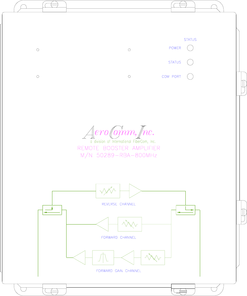
PROGRAMMABLE BI-DIRECTIONAL BOOSTER AMPLIFIER OVERVIEW:
(refer to figure 1)
The Programmable Bi-directional Booster Amplifier (PBBA) is a software-
driven user-configurable unit for use in a multi-carrier low signal-level
environment. It is capable of eight (8) carriers and a composite power of –
20dBm.
The forward channel covers 100 to 2000MHz and within this band a
bandpass filter defined window called the In-Band has a user settable gain. The
factory default setting is 20dB. The Out-of-Band gain is also user settable and
the factory default setting is 0dB. The reverse channel covers 100 to 2000MHz
and has a user settable gain (see specifications for min/max gain/loss setting for
the forward and reverse channels.) Each channel uses a broadband
attenuator/amplifier module in which the attenuation is digitally set via computer
interface.
There are two (2) parallel amplifiers in the forward channel. One of the
forward channels called In-Band has a high gain amplifier chain and a band pass
filter to boost a specific window of frequencies within the 100 to 2000MHz
frequency of operation.
Its small package and light weight allows the user to conveniently install
the unit. Indicator lights allow the user to determine the status of the unit from a
distance. User-friendly software enhances the unit’s performance and user
interface.
ACI-OIM-0001 RELEASED ER # AC—0010 9/16/99 7
PROGRAMMABLE BI-DIRECTIONAL BOOSTER AMPLIFIER
PBBA
MODEL 50289-RBA-800MHz
P/N 50483-02-25
FIGURE 1

ACI-OIM-0001 RELEASED ER # AC—0010 9/16/99 8
II. SPECIFICATIONS
GENERAL SPECIFICATIONS:
PROGRAMMABLE BI-DIRECTIONAL BOOSTER AMPLIFIER
P/N 50483-02-25
MODEL # 50289-RBA-800 MHz
SPECIFICATIONS DEFAULT NOMINAL ADJUSTMENT
RANGE
Forward Channel: Talk-Out (Outbound)
Reverse Channel: Talk-In (Inbound)
Forward Freq. Range (Out-of-Band): 100 to 819/826 to 2000 MHz
Forward Freq. Range (In-Band): 821 to 824 MHz
Forward GAIN Range (Out-of-Band): 20 ± 2dB 11 to 26
Forward GAIN Range (In-Band): 0 ± 2dB
Reverse gain 100 to 2000 MHz: -1dB ± 1dB
RF Power out, 1 carrier, 1 dB
compression: +17dBm
Max Power input 8 tone no damage: -12dBm/carrier
Max Power input: -20dBm
Amp Flatness: +0, -2dB
Intermodulation Distortion: -50dBc
Second Harmonic Output: -40dBc
Spurious Outputs: -80dBc
Noise Figures: <20dB
Input/Output VSWR: 1.3:1
Power Requirement: 120VAC
Input/Output Connector: Type N
AC Power Input: ¾” Conduit
Comm. Port: DB9F
Housing (Enclosure) Type: NEMA 4x
Enclosure Size: 14”x12”x6” (LxWxD)
Operation Temp.: -30 to +60ºC
FCC type acceptance

ACI-OIM-0001 RELEASED ER # AC—0010 9/16/99 9
SUB-ASSEMBLY SPECIFICATIONS:
ATTENUATOR AMP MODULE #1 & #2
P/N 50483-02-26-01
MODEL #
SPECIFICATIONS
Frequency Range: 100 – 2000 MHz
Attenuation: 0dB min, -15db max
Gain @ 0dB attenuation: 18dB min, 20 dB max
Flatness: +1dB
Power: 12VDC @ 19mADC
I/O Connection: SMA female
Zin/Zout: 50 ohm
ATTENUATOR AMP MODULE #3
P/N 50483-02-26-01
MODEL #
SPECIFICATIONS
Frequency Range: 819 – 826 MHz
Attenuation: 0dB min, -15db max
Gain @ 0dB attenuation: 18dB min, 20 dB max
Flatness: +1dB
Power: 12VDC @ 19mADC
Isolation: 20dB min
I/O Connection: SMA female

ACI-OIM-0001 RELEASED ER # AC—0010 9/16/99 10
MMIC #1
P/N 50483-02-27
MODEL #
SPECIFICATIONS
Frequency Range: 100 - 2000 MHz
Gain: 10dB typical
Gain Flatness: <+1dB
Power: 12VDC @ 85mA
I/O Connection: SMA female
Zin/Zout: 50 ohm
MMIC #2
P/N 50483-02-30
MODEL #
SPECIFICATIONS
Frequency Range: 819 – 826 MHz
Gain: 20dB typical
Gain Flatness: +0.1dB
Power: 12VDC @ 120mA
I/O Connection: SMA female
Zin/Zout: 50 ohm
ACI-OIM-0001 RELEASED ER # AC—0010 9/16/99 11
III. INSTALLATION
The Programmable Bi-Directional Booster Amplifier is housed in a steel
NEMA 4 enclosure. The enclosure has four mounting tabs on its rear surface
(refer to drawing 50483-05-17). In selecting a mounting surface, the size and
weight of the unit must be considered.
The RF cables to the radiators (distribution system) are connected to
female N-connectors on the bottom of the enclosure. Special care should be
taken in the dress and separation of these cables to prevent signal coupling
between the input and output of the PBBA.
The PBBA requires a 110VAC power source. It is recommended, to
maintain the integrity of the NEMA enclosure, that the AC power should enter
using conduit or a connector. A cutout for a ¾” conduit connector is provided at
the bottom of the enclosure.
Connect the unit as follows:
RF CABLE CONNECTIONS (refer to drawing 50483-01-18):
1) Talk Out: to radiating cable run to 8-Channel Booster Amplifier.
2) Power: to AC conduit see also figure XX.
3) Com Port: for calibration only - no connection required at installation.
4) Talk In: to radiating cable run to end of tunnel.
AC POWER INTERCONNECT (refer to drawing 50483-01-15):
The AC power signals are connected to an internal terminal block. The
terminal block is located on the lower plate assembly at the center of the lower
edge. To access the lower assembly, the upper plate must be removed.
Remove the upper plate as follows:
1) Disconnect the Talk Out and the Talk In cables.
2) Remove the four #10-32 screws.
Connect the AC sources as follows:
3) The ground wire from the AC conduit connects to terminal 1.
4) The AC high wire from the AC conduit connects to terminal 2.
5) The neutral wire from the AC conduit connects to terminal 3.
Re-install upper plate:
1) Secure plate to standoff.
2) Reconnect the two cables; check all cables are tightly secured.
ACI-OIM-0001 RELEASED ER # AC—0010 9/16/99 12
IV. EQUIPMENT INITIALIZATION
To Initialize Equipment:
1) Depress in the Circuit Breaker On/Off switch.
2) Observe on the front door: Power LED: On
Status LED: Flashing at 1 Hz rate
Con LED: Off
3) Close panel and secure door locks.
There is no special requirement to operate the equipment; it is designed for
unattended operation. Turn on and secure, close the door.
ACI-OIM-0001 RELEASED ER # AC—0010 9/16/99 13
V. MAINTENANCE SCHEDULE
The Programmable Bi-directional Booster Amplifier is designed for unattended
operation requiring minimal maintenance. General maintenance consists of equipment
inspection and operational tests. Periodical equipment tune-up and alignment is
recommended.
Cable Inspection:
The external and internal cables and connectors should be checked for
indication of corrosion.
Enclosure Inspection:
The interior of the enclosures should be inspected for evidence of
condensation.
LED Inspection:
Power LED: ON
Status LED: Flashing at 1 Hz rate
Con LED OFF
The performance of operations testing is recommended to be done semi-
annually. Operational testing will indicate equipment status determining if an alignment
is necessary.
ACI-OIM-0001 RELEASED ER # AC—0010 9/16/99 14
VI. THEORY OF OPERATION
The PBBA is a broadband bi-directional amplifier. It has 3 channels, 2 in the
forward direction and 1 in the reverse direction. In the forward direction are two parallel
channels. One channel has a high gain amplifier chain and a band pass filter. This
channel boosts the signals that come through the filter. These are the inbound signals.
Above and below the filter passband are the outbound signals which are within the 100
to 2000 MHz range and are handled by the other channel in the forward direction. Both
channels use a broadband attenuator/amplifier module which has a 15dB dynamic
range and a gain of around 20dB at 0dB attenuation setting. The attenuation, therefore
the overall module gain/loss, is digitally set via computer interface.
The filter in the inbound channel attenuates the outbound signals from 100 to
2000 MHz, but is amplified again in the out of band channel. The difference in these
two channels is the high gain amplifier in the In-band channel.
The reverse channel also uses the same broadband attenuator module, and
covers the same frequency range, 100 to 2000 MHz. Due to the configuration of the
reverse channel its losses are higher and a medium gain amplifier follows the attenuator
module to enhance channel gain.
With the 3 channels integrated, the unit provides bi-directional amplification of
inbound signals.

ACI-OIM-0001 RELEASED ER # AC—0010 9/16/99 15
VII. TROUBLESHOOTING
PROBLEM SOLUTION ON-SITE-REMEDY
1) Power Indicator is off a) Check if the unit is
plugged into a 120VAC
source.
b) Check if the internal
circuit breaker on/off
switch is depressed
Plug in the unit to 120VAC
or depress internal circuit
breaker.
2) Power indicator on but
status light is not blinking Check connection to the
microprocessor board Microprocessor board is
faulty. Pull out for repair.
3) Comport does not light
up when unit is
programmed
Check serial cable
connections
4) Unit does not respond
when programmed Check serial cable
connections
5) Unit does not provide
designed gain or unit does
not have gain at all or
intermittent operation
a) Check RF connection
between modules
b) Check Talk In/Talk Out
RF connections

ACI-OIM-0001 RELEASED ER # AC—0010 9/16/99 16
III. SCHEMATICS,
ASSEMBLY DRAWINGS,
PARTS LISTS
Remote Booster Amplifier 800 MHz
50483-02-25 ASSEMBLY REMOTE BOOSTER AMPLIFIER 800 MHz
50483-02-25 PARTS LIST REMOTE BOOSTER AMPLIFIER 800 MHz
50483-02-26 ASSEMBLY ATTENUATOR AMP MODULE #1
50483-02-26 PARTS LIST ATTENUATOR AMP MODULE #1
50483-03-55 PCB ASSY BOOSTER ATTENUATOR
50483-03-55 PARTS LIST BOOSTER ATTENUATOR
50483-04-55 SCHEMATIC DIAGRAM BOOSTER ATTENUATOR
50483-07-55 PCB FABRICATION BOOSTER ATTENUATOR
50483-07-47 PCB FABRICATION ISOLATOR INTERFACE
50483-05-46 HOUSING
50483-05-47 COVER
50483-02-27 ASSEMBLY MMIC AMP MODULE #1
50483-02-27-01 PARTS LIST MMIC AMP MODULE #1A
50483-03-46 PCB ASSY MMIC AMPLIFIER
50483-03-46 PARTS LIST MMIC AMPLIFIER
50483-04-46 SCHEMATIC MMIC AMPLIFIER
50483-07-46 FABRICATION MMIC AMPLIFIER
50294-05-01 MECHANICAL ASSY LNA HOUSING
50294-05-02 MECHANICAL ASSY COVER MOUNTING PLATE
50483-02-30 ASSEMBLY MMIC AMP MODULE #2
50483-02-30 PARTS LIST MMIC AMP MODULE #2
50483-03-54 PCB ASSY MMIC AMP #2
50483-03-54 PARTS LIST MMIC AMP #2
50483-04-54 SCHEMATIC MMIC AMP #2
50483-07-54 FABRICATION MMIC AMP #2
50294-05-01 MECHANICAL ASSY LNA HOUSING
50294-05-02 MECHANICAL ASSY COVER MOUNTING PLATE
50483-02-28 ASSEMBLY RBA BPF MODULE
50483-02-28 PARTS LIST RBA BPF MODULE
50483-03-24 PARTS LIST LNA BPF
50483-04-24 SCHEMATIC LNA BPF
50483-07-24 FABRICATION LNA BPF
50483-05-51 MECHANICAL ASSY BPF HOUSING
50483-05-52 MECHANICAL ASSY BPF COVER
50483-05-49 MECHANICAL ASSY MOUNTING PLATE FILTER
50483-05-83 MYLAR CUTOUTS BPF HOUSING
50483-05-50 MECHANICAL ASSY ENCLOSURE
50483-05-53 MECHANICAL ASSY LOWER COMPONENT PLATE
50483-05-54 MECHANICAL ASSY UPPER COMPONENT PLATE
50583-05-55 MECHANICAL ASSY POWER SUPPLY MOUNTING PLATE
50483-05-56 MECHANICAL ASSY POWER SHIELD
ACI-OIM-0001 RELEASED ER # AC—0010 9/16/99 17
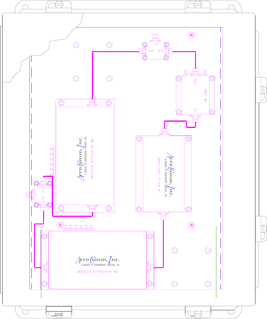
PROGRAMMABLE BI-DIRECTIONAL BOOSTER AMP
ACI-OIM-0001 RELEASED ER # AC—0010 9/16/99 18
ATTENUATOR/AMPLIFIER MODULE #1 & #2
ACI-OIM-0001 RELEASED ER # AC—0010 9/16/99 19
ATTENUATOR/AMPLIFIER MODULE #3
ACI-OIM-0001 RELEASED ER # AC—0010 9/16/99 20
MMIC AMPLIFIER #1
ACI-OIM-0001 RELEASED ER # AC—0010 9/16/99 21
MMIC AMPLIFIER #2
ACI-OIM-0001 RELEASED ER # AC—0010 9/16/99 22
RBA BPF MODULE
ACI-OIM-0001 RELEASED ER # AC—0010 9/16/99 23
IX. PERTINENT DOCUMENTATION
Other documents needed for the operation of the Programmable Bi-directional Booster
Amplifier Include the following:
1) Programmable Bi-directional Booster Amplifier software manual
ACI-OIM-0001 RELEASED ER # AC—0010 9/16/99 24
X. RECOMMENDED SPARES
The following spares are recommended:
Due to the installation location of the Programmable Bi-directional Booster
Amplifier we recommend a complete upper and lower component plate assembly
spare. For quick in field service, swap.
For shop/repair service, we recommend the following spares as module
replacements:
1 Attenuator Amplifier Module #1
1 Attenuator Amplifier Module #2
1 Attenuator Amplifier Module #3
1 MMIC Amplifier #1
1 MMIC Amplifier #2
1 RBA Band Pass Filter Module