AeroScout BS2035-1 EXCITER User Manual AeroScout Exciter v2 0 User Guide rev1
AeroScout EXCITER AeroScout Exciter v2 0 User Guide rev1
USERS MANUAL

AeroScout Exciter
Version 2.0
User Guide
1450 Fashion Island Blvd.
Suite 510
San Mateo, CA 94404
Tel: 650-571-0800
Fax: 650-571-6660
www.aeroscout.com
Disclaimer
The information and know-how included in this document are the exclusive property of
AeroScout Inc. and are intended for the use of the addressee or the user alone. The
addressees shall not forward to another their right of using the information, know-how or
document forwarded herewith, in whole or in part in all matters relating or stemming from
or involved therein, whether for consideration or without consideration, and shall not
permit any third party to utilize the information, know-how or the documents forwarded
herewith or copies or duplicates thereof, unless at the company’s consent in advance and
in writing. Any distribution, advertisement, copying or duplication in any form whatsoever
is absolutely prohibited. The Company reserves the right to sue the addressee, user
and/or any one on their behalves, as well as third parties, in respect to breaching its
rights pertaining to the intellectual rights in particular and its rights of whatever kind or
type in the information, know-how or the documents forwarded by them herewith in
general, whether by act or by omission.
This document is confidential and proprietary to AeroScout Inc. and is not to be
distributed to any persons other than licensed AeroScout Exciter users or other persons
appointed in writing by AeroScout Inc.
Trademark Acknowledgements
AeroScout™ is a trademark of AeroScout Inc. Other brand products and service names
are trademarks or registered trademarks of their respective holders.
Copyright 2003-2005 AeroScout Inc. All rights reserved.

Table of Contents | 3
Table of Contents
Introduction................................................................................................5
Application and Industry Examples ..............................................................5
Features ....................................................................................................6
Exciter Hardware........................................................................................7
LED Indications ........................................................................................................................7
Connectors Panel.....................................................................................................................8
Installing the Exciter..................................................................................10
Preparing the Cables and Connectors .............................................................................. 10
Configuring the Exciter......................................................................................................... 10
Mounting the Exciter............................................................................................................. 11
Exciter Specifications................................................................................12
Range...................................................................................................................................... 12
Physical and Mechanical..................................................................................................... 12
Network Interface.................................................................................................................. 12
Power...................................................................................................................................... 12
Management.......................................................................................................................... 12
Environmental Specifications .............................................................................................. 12
LF Channel............................................................................................................................. 12
Certification ............................................................................................................................ 13

Introduction | 5
Introduction
The AeroScout Exciter is a component of the AeroScout suite of enterprise
visibility solutions that enables location-based applications. The Exciter
extends the AeroScout suite to provide robust and sophisticated RFID
detection capabilities, using the same AeroScout tags that can also be
accurately located in real time by the AeroScout system.
The Exciter triggers AeroScout’s T2 tags as they pass through a choke point,
and those transmit a message to AeroScout Location Receivers in range.
This provides instant acknowledgment that a tagged asset passed through a
gate, doorway or some other well-defined area. The detection capabilities of
the Exciter, combined with the location features of the AeroScout Location
System, make the AeroScout suite the most sophisticated enterprise visibility
solution for a wide variety of industries.
Figure 1: Exciter positioned at choke point triggering a tag
Application and Industry Examples
High value asset tracking
Health care facilities and general enterprises can tag valuable assets that are
intended to stay within a certain area. The AeroScout system can track the
location of those assets, and if they leave through an exit or enter a restricted
area, the Exciter triggers a tag message.
Process control
Manufacturing and supply chain facilities can track the location and presence
of equipment and in-process inventory as it moves through the production
process. This gives an enterprise a real-time view of which (and how many)
assets have passed each step in the process, enabling better supply chain
management.

6 | Features
Inventory management
Logistics and manufacturing enterprises can automatically update inventory
records as inventory enters and leaves the warehouse, ensuring real-time
knowledge of levels without manual checks or physical scanning.
Security applications
Government agencies and enterprises can tag secure assets and people that are
restricted to certain areas or require historical location tracking. If those assets
leave through an exit or enter a restricted area, Exciter triggers a tag message.
Features
RFID detection of AeroScout T2 tags
Triggering the tags to transmit as they pass through a defined area, Exciters
reach up to a 6m (18 ft) range, enough to cover wide gate areas.
Tag behavior modification:
Wireless activation and deactivation of tags. Tag battery life can be extended
further by switching the tags off when they leave a defined tracking area
through a gate or doorway.
Change of tag transmission rate temporarily or indefinitely to accommodate
different usage patterns in various physical spaces.
Message Programming functions
Provide the ability to use the Exciter to store messages on the tag for later
transmission. Message transmission can later be triggered by other Exciters,
enabling sophisticated process control functions.
Exciters can trigger a tag to:
• Send up to 10 bytes of data
• Transmit one of 10 pre-stored messages
• Send and store up to 10 bytes of data
Rugged IP65 enclosure
To use in hostile indoor or outdoor environments and in a wide temperature
range.
Ethernet connectivity
Enables centralized programming, monitoring and software updates by the
AeroScout Engine.

Exciter Hardware | 7
Exciter Hardware
The AeroScout Exciter includes:
• Rugged IP65 rated enclosure
• Three RJ-45 interfaces
• Single power connector
• Mounting adapter
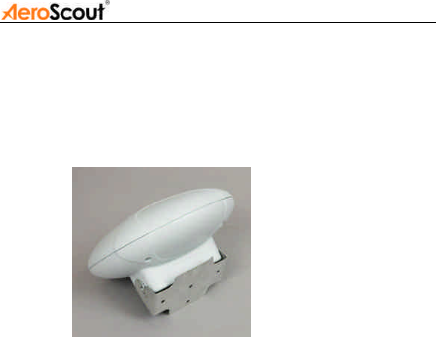
Figure 2. AeroScout Exciter v2.0
LED Indications
The front panel of the Exciter consists of three LEDs. Figure 3 describes
these LEDs.
Figure 3. LED Indicators
1 Power – Green LED indicates that the unit is ON and connected to a
power source.
1 2 3

8 | Exciter Hardware
2 Status – Green LED indicates the unit’s operational status.
a. Blinking (according to transmission interval) – Exciter is
transmitting LF signals.
b. Off - Fault
3 Link – Orange LED indicates active Ethernet communication (In offline
mode, when not connected to the network, this LED should be off).
Connectors Panel
Figure 4 describes the Exciter connectors panel (bottom panel).
Figure 4. AeroScout Exciter Connectors Panel
1. Ethernet LAN Connection – RJ-45 interface. In a configuration that uses
physical Ethernet cable connection to the LAN, the network cable is attached
here. Permanent connection to a wired network is not mandatory. However
you must have a wired connection for configuring the Exciter. In addition,
some of the monitoring functions will not be available if the Exciter is not
wired. This connection shall be used also for PoE (802.3af).
2. Power jack – Fit for 24VAC, 24VDC and 48VDC. The power adapter plug
(see 5) supplied with the Exciter, should be assembled to a power cord and
connected to the power jack. Alternatively, you can use the power supply that
is packaged along with the Exciter. When PoE is used, this connection is not
required.
3. Power and Control IN Connector – RJ-45 connector. This connector is
used for distributing power, Serial connection and Data to chained Exciters.
Chaining configuration is currently not supported by AeroScout Engine.
4. Power and Control OUT Connector – RJ-45 connector. This connector
is used for distributing power , Serial connection and Data to chained
1 2 3
5
6
4
4

Exciter Hardware | 9
Exciters.
GPIO – one input and one output (optionally).
Chaining configuration is currently not supported by AeroScout Engine.
5. Termination Switch – For defining termination settings in chained
Exciters installations. Default factory setting is Termination On (o-o).
Chaining configuration is currently not supported by AeroScout Engine.
6. Chaining/Control Switch – For defining the Exciter setting to Control or
Chaining. Default factory setting is Chaining which is the viable setting for
single Exciters also.
Chaining and Control configuration is currently not supported by AeroScout
Engine.
Sealing the connectors panel
It is recommended to seal the Exciter connectors panel after connecting the
required cables.

10 | Installing the Exciter
Installing the Exciter
This section explains how to install an Exciter unit.
Preparing the Cables and Connectors
Network:
Connect the LAN cable to the LAN connection on the
Exciter.
Power:
Connect the power cable to the power jack.
Configuring the Exciter
Exciters are configured using the AeroScout System Manager. The
configuration settings consist of device installation and network definitions.
The configuration procedure involves the following steps:
1. Connect all Exciters with a wired Ethernet connection to a dedicated
segment.
2. Add the Exciters to the system and define their IP settings (IP, subnet,
gateway, ports) in the System Manager.
3. Verify that the Exciters’ status is OK.
4. Position the Exciter in the site according to site survey recommendations,
and mount it.
5. Align the Exciters’ positions according to the required area coverage.
6. Configure the Exciter’s settings.
7. If you wish to define the Exciter as an offline Exciter that is not
connected to the network, you should approve the above configuration,
wait for a confirmation, define the Exciter as disconnected from network,
approve the settings again and disconnect the Exciter from the network.
Installing the Exciter | 11
Mounting the Exciter
The Exciter can be mounted on a wall using the mounting adapter (provided
with the Exciter). The mounting adapter includes five optional screw holes
that can be mounted to a wall, a ceiling or any other placement as shown in
Figure 3. The adapter also has a swivel with which it can be adjusted in various
angles. After setting the required angle, fasten the screws on the sides of the
mounting adapter.
Figure 3. Exciter Mounting Adapter

12 | Exciter Specifications
Exciter Specifications
Range
• Adjustable range up to 6 m (18 feet)
• Supports AeroScout T2 Tags
Physical and Mechanical
• Dimensions: 220mm (8.6 inches) diameter, 115mm (4.5
inches) depth
• Weight: 800g (28 oz.)
• Housing: IP65 Rugged Enclosure
Network Interface
• Ethernet (RJ-45)
Power
• Input voltage: 24VAC, 24VDC, 48VDC
• PoE (802.3af)
• Maximum Power Dissipation: 10W
Management
• All settings configured remotely using AeroScout
Engine’s System Manager.
Environmental Specifications
• Operating temperature: -20°C to +60°C (-4°F to
140°F)
• Humidity: 0 to 95%, non-condensing
LF Channel
• 125kHz
• Field intensity limits: 37.3dBµA/m at 10m (ETSI)
• Propagation limits: 21.8dBµV/m at 300m (FCC)
• Modulation: ASK

Exciter Specifications | 13
Certification
• Radio:
FCC Part 15, Sub-part B, Class B, Sub-part C
EN 300-330, EN 301-489
RSS210 (Canada)
• Safety:
CE, cTUVus (EN60950)

14 |
Safety and Warnings
FCC STATEMENT
This equipment has been tested and found to comply with the limits for a Class B digital
device, pursuant to Part 15 of the FCC rules. These limits are designed to provide
reasonable protection against harmful interference in a residential installation. This
equipment generates uses and can radiate radio frequency energy and, if not installed
and used in accordance with the instructions, may cause harmful interference to radio
communications. However, there is no guarantee that interference will not occur in a
particular installation. If this equipment does cause harmful interference to radio or
television reception, which can be determined by turning the equipment off and on, the
user is encouraged to try to correct the interference by one or more of the following
measures:
a) Reorient or relocate the receiving antenna.
b) Increase the separation between the equipment and receiver.
c) Connect the equipment to an outlet on a circuit different from that to which the
receiver is connected.
d) Consult the dealer or an experienced radio/TV technician.
This device complies with Part 15 of the FCC Rules.
Operation is subject to the following two conditions:
a) This device may not cause harmful interference
b) This device must accept any interference received, including interference that may
cause undesired operation.
FCC Warning
Modifications not expressly approved by the manufacturer could void the user authority to
operate the equipment under FCC Rules.
Instructions concerning human exposure to radio frequency
electromagnetic fields.
To comply with FCC Section1.307 (b)(1) for human exposure to radio frequency
electromagnetic fields, implement the following instruction: A distance of at least 20 cm
between the equipment and all persons should be maintained during operation of the
equipment.
Warranty
Hardware. AeroScout Inc. ("AeroScout"), warrants that commencing from the date of
delivery to Customer, and continuing for a period of one year the Hardware will be free
from defects in material and workmanship under normal use. The date of shipment of a
Product by AeroScout is set forth on the packaging material in which the Product is
shipped. This limited warranty extends only to the original user of the Product. Customer's
sole and exclusive remedy and the entire liability of AeroScout and its suppliers under this
limited warranty will be, at AeroScout’s or its service center's option, shipment of a
replacement within the period or a refund of the purchase price if the Hardware is
returned to the party supplying it to Customer, if different than AeroScout, freight and
insurance prepaid. AeroScout replacement parts used in Hardware repair may be new or
equivalent to new. AeroScout’s obligations hereunder are conditioned upon the returned
of affected articles in accordance with AeroScout’s then-current Return Material
Authorization (RMA) procedures.
Restrictions. This warranty does not apply if the Product (a) has been altered, except by
AeroScout, (b) has not been installed, operated, repaired, or maintained in accordance
with instructions supplied by AeroScout, (c) has been subjected to abnormal physical or

15
electrical stress, misuse, negligence, or accident; or (d) is sold for beta, evaluation,
testing, or demonstration purposes for which AeroScout does not receive a payment of
purchase price or license fee.
DISCLAIMER OF WARRANTY. EXCEPT AS SPECIFIED IN THIS WARRANTY, ALL EXPRESS
OR IMPLIED CONDITIONS, REPRESENTATIONS, AND WARRANTIES INCLUDING, WITHOUT
LIMITATION, ANY IMPLIED WARRANTY OR CONDITION OF MERCHANTABILITY, FITNESS
FOR A PARTICULAR PURPOSE, NONINFRINGEMENT, SATISFACTORY QUALITY OR ARISING
FROM A COURSE OF DEALING, LAW, USAGE, OR TRADE PRACTICE, ARE HEREBY
EXCLUDED TO THE EXTENT ALLOWED BY APPLICABLE LAW. TO THE EXTENT AN IMPLIED
WARRANTY CANNOT BE EXCLUDED, SUCH WARRANTY IS LIMITED IN DURATION TO THE
WARRANTY PERIOD. BECAUSE SOME STATES OR JURISDICTIONS DO NOT ALLOW
LIMITATIONS ON HOW LONG AN IMPLIED WARRANTY LASTS, THE ABOVE LIMITATION
MAY NOT APPLY TO YOU. THIS WARRANTY GIVES YOU SPECIFIC LEGAL RIGHTS, AND
YOU MAY ALSO HAVE OTHER RIGHTS, WHICH VARY FROM JURISDICTION TO
JURISDICTION.
This disclaimer and exclusion shall apply even if the express warranty set forth above fails
of its essential purpose.