AeroScout FM AeroScout Fall Monitor M310, M210 User Manual
AeroScout AeroScout Fall Monitor M310, M210
User Manual
[Safe. Secure. Efficient.]
Fall Management System
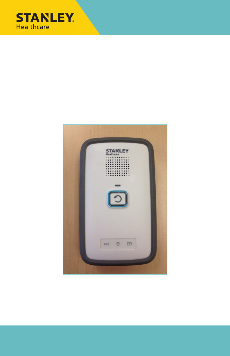
M310 Fall Monitor
Setup & User Guide
For Evaluation Purposes

Copyright Information
All content herein is the property of STANLEY Healthcare, its
Affiliates, or their content suppliers and is protected by United States
and international copyright laws. The compilation of all content is
likewise the exclusive property of STANLEY Healthcare (or the Affiliate
identified in any copyright notice) and is protected by United States
and international copyright laws.
The trademarks, service marks and logos (the ‘Trademarks’) used
and displayed in this publication are registered and unregistered
Trademarks of STANLEY Healthcare, its Affiliates and others. Nothing
herein should be construed as granting, by implication, estoppel or
otherwise, any license or right to use any Trademark displayed herein
without the prior consent of the Trademark owner. STANLEY and
the STANLEY design are two of the trademarks owned by STANLEY
Healthcare and/or its Affiliates (“STANLEY Trademarks”). STANLEY
Trademarks may not be used in connection with any product or service
that is not manufactured by or under license from STANLEY Healthcare
or its appropriate Affiliate.
Important Recommendation
STANLEY Healthcare’s systems are designed to assist staff in providing
a high degree of safety for people and assets and therefore should be
used as a component of a comprehensive safety program of policies,
procedures, and processes. As with every safety system, STANLEY
Healthcare highly recommends regular system operational checks to
verify functional integrity.
There are no known issues with the usage of this equipment in
association with other investigations or treatments at the facility.
Cautions and Warnings
ii M310 Fall Monitor – Setup & User Guide
FAILURE TO HEED THE FOLLOWING CAUTIONS COULD RESULT IN HARM TO YOUR
SYSTEM OR CAUSE IT TO FUNCTION IMPROPERLY, INTERMITTENTLY, OR NOT AT ALL.
• Use the M310 Fall Monitor only with approved accessories.
• Remove batteries when the Monitor is not in use to avoid battery
power loss.
• Use care when connecting the Sensormat® pads. Gently remove or
connect cords. Pulling on cords may damage them and/or result in
system failure.
CAUTION

M310 Fall Monitor – Setup & User Guide iii
FAILURE TO HEED THE FOLLOWING WARNINGS COULD RESULT IN INJURY TO OR THE
DEATH OF PERSONS IN YOUR CARE.
• A low battery condition in the Monitor is indicated by the Low Battery
indicator flashing YELLOW once every 3 seconds. Immediately change
the monitor’s batteries.
• Test the M310 Fall Monitor and Sensormat pad before each use and
inspect the cords and pads for signs of damage. Immediately replace
any components with signs of wear or damage.
• Sensormats may not be effective with air type bed mattresses or air
type chair cushion pads; test before using.
• Do not place the monitor within 1 ft. (0.3m) of and facing the resident.
Placing the Monitor on a wheelchair back is acceptable as long as the
monitor is facing away from the resident.
• The M310 Fall Monitor is only one part of your facility’s fall
management program. The M310 Fall Monitor is not a substitute for
proper nursing care or routine visual monitoring by caregivers. The
effectiveness of the M310 Fall Monitor relies entirely on an immediate
response by the caregiver to the M310 Fall Monitor system alarm.
• The M310 Fall Monitor system will not stop a person from leaving a
bed or chair. It is intended only to alert a caregiver that a patient or
resident may need assistance. Other interventions may be required.
• Keep the Sensormat pad flat at all times. Folding the pad may damage
it. Do not use the pad if it has been folded.
• Do not immerse the Sensormat pads in liquids. The pad will not
operate properly if the pad is exposed to excessive liquids. If the pad is
immersed in liquid, discard it immediately.
• Operators of this equipment must be familiar with the functions and
usage as described in this manual, and must be properly trained in the
resident care policies and procedures of the facility.
• Any modification of this equipment is not allowed, voids all
warranties, and may result in injury to or death of persons in your
care.
WARNING
CAUTION
RISK OF EXPLOSION IF BATTERY IS REPLACED BY AN INCORRECT TYPE.
DISPOSE OF USED BATTERIES ACCORDING TO THE INSTRUCTIONS.
ATTENTION
RISQUE D’EXPLOSION SI LA PILE EST REMPLACÉE PAR UN TYPE INCORRECT.
SE DÉBARRASSER DES PILES USAGÉES SELON LES INSTRUCTIONS.

iv M310 Fall Monitor – Setup & User Guide
Contents
Copyright Information ....................................................................................................ii
Important Recommendation ....................................................................................... ii
Cautions and Warnings................................................................................................... ii
Image of components to go here .............................................................................. vi
Introduction ................................................................................................. 1
Check Your Shipment ......................................................................................................1
Other Components Sold Separately .......................................................................... 1
General Overview ....................................................................................... 2
Hardware Features .................................................................................... 3
Speaker Opening .............................................................................................................. 4
Reset Button .......................................................................................................................4
Status Indicators ...............................................................................................................4
Wheelchair Mounting Clips ..........................................................................................5
Wall Mounting Bracket ...................................................................................................5
Battery Cover ......................................................................................................................5
Settings ................................................................................................................................5
Power Supply Connector ............................................................................................... 6
Nurse Call Cable Connector .......................................................................................... 6
Sensormat Pad Connectors ...........................................................................................6
Additional Features ..........................................................................................................6
Alerts and Status Indicators ...................................................................... 6
Reset Button Red LED .....................................................................................................6
Reset Button Green LED ................................................................................................. 6
Yellow Status Indicator Icons ........................................................................................7
Audible Alerts .............................................................................................. 7
Pad Exit Alarms .................................................................................................................. 7
Trouble Alarms...................................................................................................................7
Conrmation Tones ..........................................................................................................7
Monitor Setup ............................................................................................. 8
Pad Exit Alarm Tone Adjustments ...............................................................................8

M310 Fall Monitor – Setup & User Guide v
Custom Pad Exit Alarms ................................................................................................ 8
DIP Switch Functions ...................................................................................................... 9
Hold Mode ....................................................................................................9
Arming the Monitor .................................................................................10
Batteries and External Power .................................................................10
Replacing Monitor Batteries ......................................................................................10
External Power ................................................................................................................11
Using Sensormat Pads .............................................................................11
On a Bed ............................................................................................................................11
On a Chair ......................................................................................................................... 12
Testing the Sensormat Pad .....................................................................12
Changing the Sensormat Pad .................................................................13
Monitor Mounting/Installation Options ..............................................14
Wall Mounting ................................................................................................................14
Strain Relief ...................................................................................................................... 14
Chair or Bed Footboard Mounting ..........................................................................15
Interfacing with a Nurse Call System ....................................................15
Nurse Call Alarms ...........................................................................................................17
Summary of Audible Alerts and Tones .................................................18
Maintenance ..............................................................................................19
System Specications ..............................................................................20
Regulatory Compliance ...........................................................................21
Warranty Information ..............................................................................23

vi M310 Fall Monitor – Setup & User Guide
Image of components to go here

Introduction
M310 Fall Monitor – Setup & User Guide 1
Introduction
The STANLEY Healthcare M310 Fall Management System uses a
pressure-sensitive pad to detect the presence of a patient/resident, and
a monitor to notify facility staff in the event of premature departure
from a bed or chair.
Check Your Shipment
The M310 Fall Monitor package includes:
1 – Monitor (FM-3100) with Wall Mounting Bracket, bed/
wheelchair clip, and built-in rubber bumper
1 – Wall Mounting Bracket Kit (Part#???), including:
• 1 – Wall Mounting Bracket (WMB-1000)
• 6 – Dual-Lock® 250 Fastener strips (2” x ¾” each) (Part#???)
• 4 – Mounting Screws with Plastic Anchors (Part#???)
1 – Large Wire Clip (Part#???)
1 – Bed/Chair Mounting Clip (Part#???)
3 – 3V CR123A Batteries (not rechargeable) (Part#???)
This document (0980-165-000)
Other Components Sold Separately
Sensormat® pads – available in the following types:
• Chair 14-day (Part#???), Chair 180-day (Part#???), Bed 14-
day (Part#???), Bed 180-day (Part#???)
Additional Wall Mount Bracket Kits (Part#???)
Additional Wire Clips (BMB-1000)
Nurse Call Cables (Part#???) - grey, 8’ long, ¼ mono jacks
Toilet pads (Part#???)
Floor pads (Part#???)
Seatbelt pad (Part#???)
Remote call button with Y-splitter (Part#???)

General Overview
2 M310 Fall Monitor – Setup & User Guide
General Overview
The M310 Fall Management System consists of pressure-sensitive
Sensormat pads which detect the presence of a patient/resident, and a
monitor which provides staff with alert and alarm information.
The monitor provides two types of audible alerts, Pad Exit Alarm and
Trouble Alarm, and two types of operational Confirmation Tones,
positive or negative.
If the patient/resident exits the pad for longer than a pre-selected
number of seconds (0, 2, or 4), the monitor provides visual and
auditory alarms to alert staff that the patient/resident may need
immediate assistance.
If a technical problem prevents the pad from monitoring (e.g., pad
or nurse cable disconnect, low battery condition, etc.), the
monitor provides visual and audible alerts to notify staff that the
patient/resident is no longer being monitored.
If a Nurse Call system is connected, alerts can be sent to the Nurse Call
station. The staff member, having been alerted that a patient/resident
is exiting the bed or chair, can counsel the person by intercom (if
available), or provide immediate assistance.
All audible alarms can be cancelled by pressing the Reset button on the
front of the monitor.
Hardware Features
M310 Fall Monitor – Setup & User Guide 3
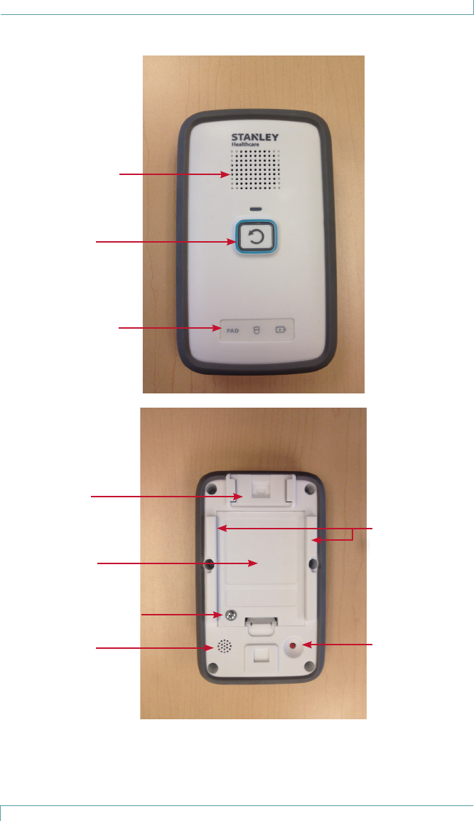
Hardware Features
Speaker Opening
Reset Button/
Alarm State
Indicator
Pad, Nurse Call
and Power status
Indicators
Mount for
Wheelchair
Small Clip
Battery Cover
Battery Cover Screw
Microphone
Opening
Guide Rails for
Wall Mounting
Bracket &
Wheelchair
Large Clip
Pairing Button
Hardware Features
4 M310 Fall Monitor – Setup & User Guide
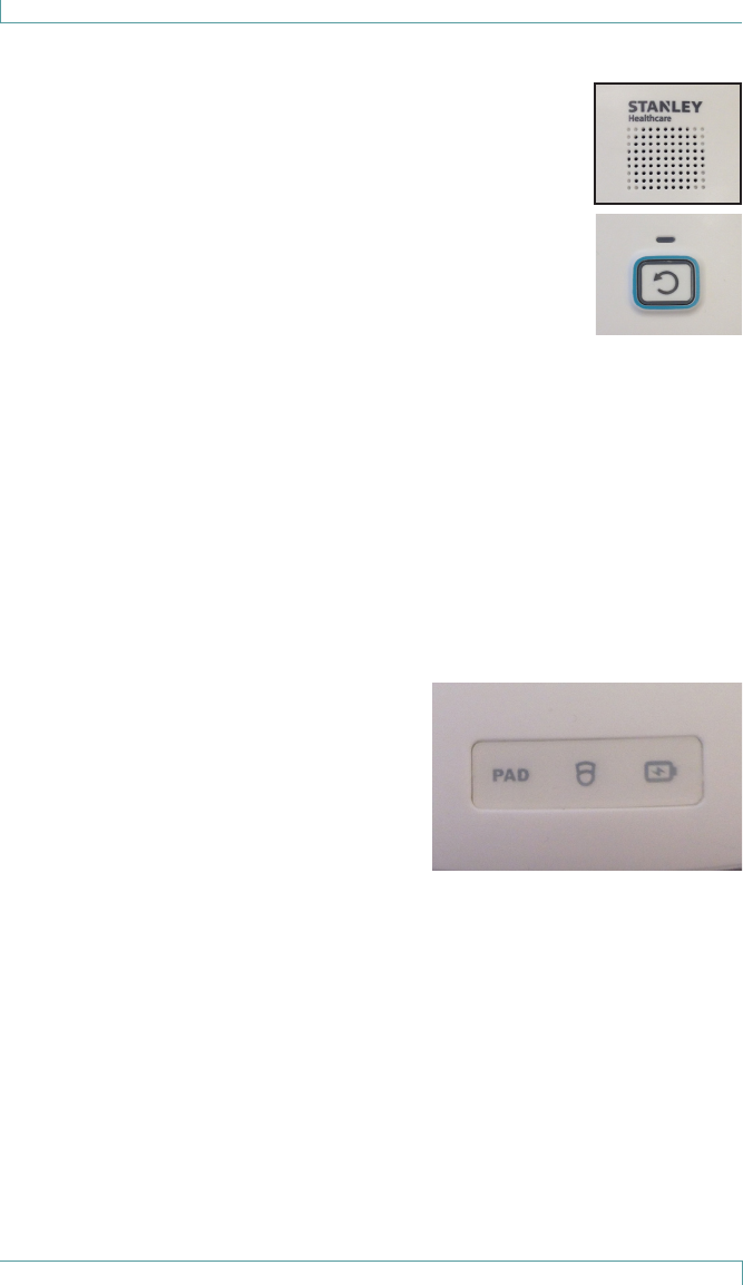
Speaker Opening
The speaker opening allows the monitor alarm to be
audible.
Reset Button
The reset button is used to display the monitor’s status
without disrupting the monitoring session, to mute
audible alerts, or to put the monitor into Hold Mode.
Hold Mode is used to suspend patient monitoring to
allow staff to move the patient temporarily (adjust
bedding, trip to the toilet, etc.)
Button press duration variations are as follows:
• A short press is used to display the monitor’s status or cancel any
audible alarms.
• A long press, more than 3 seconds, is used to place the monitor in
Hold Mode for 2 minutes (120 seconds).
Status Indicators
Pad
This LED indicates when a pad is
disconnected, or when two pads are
being monitored simultaneously. PAD
icon flashes, and honk alert sounds
every 5 seconds while 2 pads are being
monitored.
Nurse Call
Indicates when the monitor is set to remote alert using the Nurse Call
system but the cable is unplugged.
Battery
This LED flashes YELLOW on low battery, or steady GREEN with
YELLOW flashes when connected to a power supply and batteries are
low or not installed.
Hardware Features
M310 Fall Monitor – Setup & User Guide 5
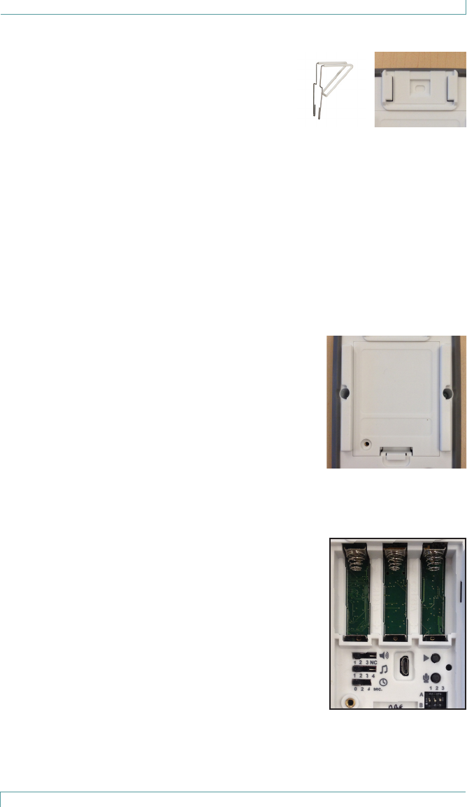
Wheelchair Mounting Clips
Use the small metal clip to attach the
monitor to surfaces up to 5/16” thick (e.g., the
back of a wheelchair).
Use the large wire clip to attach the monitor
to surfaces 5/16” to 2¼” thick (e.g., the
headboard of a bed).
For more information, see “Monitor Mounting/Installation Options” on
page 14.
Wall Mounting Bracket
Use the supplied plastic wall mounting bracket to attach the monitor
to a wall with the built-in guide rails.
Battery Cover
The battery cover is used to protect the batteries
and the settings area (alert volume, tones, etc.)
Check that the battery cover retention screw is
tightened to avoid batteries accidentally falling
out if the monitor is dropped, and to reduce the
possibility of battery theft.
For more information, see “Replacing Monitor
Batteries” on page 10.
Settings
Behind the battery cover, there are buttons and
switches used to control audible alert selection,
volume, and alert delay times.
The play and record buttons, and the microphone
are used to record custom audible pre-alerts
messages of up to 15 seconds duration, after
which the alarm sounds. The hole to the right
of the buttons allows visibility for the LED which
indicates recording in progress.
DIP switch 1 is used to enable/disable audible
alerts. DIP switch 2 is used to select between “Normally Open” and
“Normally Closed” Nurse Call systems. DIP switch 3 is not in use.

Hardware Features
6 M310 Fall Monitor – Setup & User Guide
Power Supply Connector
This is used to connect a 5V power supply.
Nurse Call Cable Connector
This is used to connect a Nurse Call cable.
Sensormat Pad Connectors
These are used to connect 1 or 2 Sensormat pads.
Additional Features
The monitor includes a latex-free rubber bumper around the perimeter
to protect the monitor damage by dropping.
Alerts and Status Indicators
LED use during normal conditions is minimized to help extend the
monitor’s battery life. State changes are triggered by incoming events
such as a press on the monitor’s Reset button, a change to the Nurse
Call jack (plugged or unplugged), low battery condition, etc.
LED alerts are displayed via the Reset button and the status indicator
LEDs.
Reset Button Red LED
The Reset button flashes red to indicate that an
unexpected pad exit has occurred. The alarm LED is easily
seen from a distance of 4 meters in normal facility lighting
conditions unless direct sunlight is falling on the monitor.
Reset Button Green LED
The Reset button flashes green while it is being armed,
when it is in Hold mode, and once when an alarm is
canceled.

Hardware Features
M310 Fall Monitor – Setup & User Guide 7
Yellow Status Indicator Icons
Yellow indicates equipment trouble, including low battery or
supervision alarms when communication is lost. Yellow accompanied
by an alarm indicates a problem that prevents the monitoring of a
patient/resident on the pad.
Audible Alerts
The monitor provides three types of audible alerts: Pad Exit Alarm,
Trouble Alarm, and Confirmation Tones.
Pad Exit Alarms
Pad Exit Alarms are sounded when a patient/resident ceases to be
monitored by the Sensormat pad.
There are 4 alarm tone sequences associated with the red alarm LED
flashes. The choice of alarm or trouble tone depends on the TONE
switch setting. Confirmation tones and alert tones are not affected by
these settings.
Trouble Alarms
Trouble alarms are indicated by a negative tone when system problems
are detected. Trouble Alarm tones are sounded once every 5 seconds
and associated with the status LED (yellow flashes):
• One sound (low) in a sequence of 3 beeps
• Two sounds (low high low high) in a sequence of 4 beeps
• Two sounds (high low high) in a sequence of 3 beeps
Confirmation Tones
Confirmation Tones (positive or negative) are sounded to verify
successful operations. These tones are much quieter than the Alarm
tone and cannot be cancelled:
• A positive confirmation tone indicates a successful association of
monitor and pad, or on pad monitoring is arming.
Monitor Setup
8 M310 Fall Monitor – Setup & User Guide
Monitor Setup
Pad Exit Alarm Tone Adjustments
Loosen the battery cover screw and remove the battery cover to reveal
the settings switches and buttons.
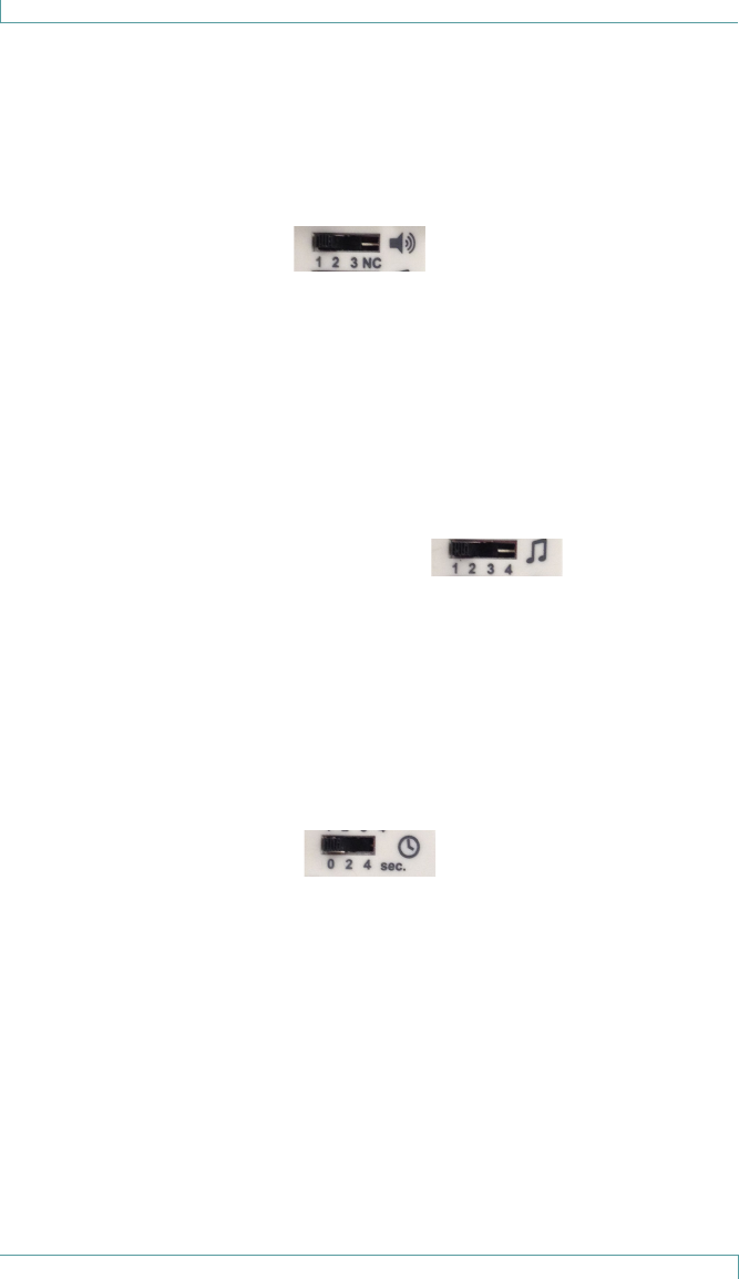
Volume (Speaker icon)
There are 4 Volume settings for the Pad Exit alarm and Trouble Alarm
tones:
• 1 - Low volume
• 2 - Medium volume
• 3 - High volume
• NC (Nurse Call) - If a Nurse Call jack is plugged in and this setting is
selected, the local alarm sound is suppressed completely, and the
alarm is sent to the Nurse Call station.
Tone Selection (Music Notes icon)
There are 4 different Alert tones which can be selected:
• 1 - One sound (low) in a sequence of 3 beeps, pause, 2 beeps
• 2 - Two sounds (low high low high) in a sequence of 4 beeps, pause,
2 beeps
• 3 - Two sounds (low high low) in a sequence of 3 beeps, pause, 2
beeps
• 4 - Two sounds (high low high) in a sequence of 3 beeps, pause, 2
beeps
Delay (Stopwatch icon)
There are 3 delay settings before the alarm is sounds:
• 0 (0 - 0.75 seconds)
• 2 (2 - 2.75 seconds)
• 4 (4 - 4.75 seconds)
Custom Pad Exit Alarms
1. The Play and Record buttons and a microphone are found to
the right of the Tone, Volume, and Delay switches.
2. Press and hold the Record button, beside the icon that looks like
a microphone.

Monitor Setup
M310 Fall Monitor – Setup & User Guide 9
3. A red LED will flash while the button is depressed. This
indicates that the device is recording.
4. Speak in a clear voice towards the microphone opening
(located at the bottom left of the monitor back) and release the
microphone button when finished.
The red LED will stop flashing.
5. Press the button beside the Play icon to hear the recorded alert.
With the right settings, the recorded message will play before
the Bed Exit Alarm.
Note: Custom audible alerts can be recorded while a Sensormat
pad is connected to the monitor, but they CANNOT
be recorded while a patient/resident is being actively
monitored.
Note: Recorded message length can be up to 15sec. Following
15sec of message recording a positive beep will sound to
indicate the recording time is over.
DIP Switch Functions
1A Don’t play the recorded message in case of alarm
1B Play the recorded message in case of alarm
2A “Normally Open” wired Nurse Call system
2B “Normally Closed” wired Nurse Call system
Hold Mode
Hold Mode is used to allow the caregiver 2 minutes to remove a
patient/resident from a monitored pad without triggering any alarms.
1. While the patient/resident is being monitored on the pad, press
and hold the Reset button on the monitor for 3 seconds or
longer.
2. A 2-minute timer is set. The patient/resident can now be
removed from the pad without triggering an alarm.
3. The reset button flashes green once per second for 115 seconds,
then flashes rapidly for the final 5 seconds, at which point a
confirmation tone sounds to indicate that Hold Mode is over.

Monitor Setup
10 M310 Fall Monitor – Setup & User Guide
4. If more time is needed, press and hold the Reset button for 3
seconds or longer again. A new 2 minute period is added to the
timer.
5. When the timer runs out, the monitor resumes normal
operation.
Arming the Monitor
Once connected to the pad, and with no patient/resident on the pad,
the monitor waits for a patient/resident to get on the pad.
When a patient/resident has been detected to be on the pad the
Reset button flashes green for 3 seconds before arming. The arming is
indicated by a positive confirmation tone plus a long green flash.
Any exit from the pad during the first 3 second flash period cancels the
arming process.
After arming, the monitor will sound a Pad Exit alarm on a pad exit.
Batteries and External Power
The monitor’s batteries will last at least 365 days (1 year) while
monitoring a person on a pad.
Note: We strongly recommend that you remove the batteries if
the monitor will not be used for an extended length of
time.
The Battery Status Indicator LED flashes a yellow warning (with a
confirmation tone) when the monitor batteries are low (approximately
within 7 days of depletion). These sequences repeat until the batteries
are replaced.
Replacing Monitor Batteries
To Remove Batteries
1. Remove the battery cover screw, and the cover.
2. Remove the batteries, ensuring that you remove the positive
end of each battery first.
Note: Dispose of used batteries according to your local
environmental laws and guidelines.

Monitor Setup
M310 Fall Monitor – Setup & User Guide 11
To Insert Batteries
1. Insert the batteries into the battery compartment, by pressing
the negative end of each battery into the corresponding spring,
then sliding the positive end into the contact.
The monitor immediately performs a self-test. The LEDs flash in
all colors and the speaker sounds.
2. Replace the battery cover, and insert and tighten the cover
screw.
External Power
External power may be used but the batteries must be installed
for back-up power. When external power is used and batteries are
installed power is drawn only from the external power.
The external power adaptor used must supply 5V/1A only. Currently,
model FRM015-505-x, (sold by STANLEY) is the only approved power
supply for the M310.
Using Sensormat Pads
Locate the Sensormat pad either on a bed or chair, directly underneath
the patient/resident.
Either 14-day or 6-month (180-day) pads can be deployed with the
monitor.
Note: Pads should be replaced on or before their warranty
period expiry date (indicated on pad).
Sensormat pads are designed to sense body-weight distributed over an
area.
Pad testing should be done either by sitting or lying on the pad, or by
pressing down firmly with the palm of your hand.
For more information on pad testing see “Testing the Sensormat Pad”
on page 12.
On a Bed
Place the Sensormat pad across the width of the bed, ON TOP OF THE
MATTRESS.
A top sheet and/or incontinence pad may be placed above the
Sensormat pad.

Monitor Setup
12 M310 Fall Monitor – Setup & User Guide
The preferred pad location is directly under the patient/resident’s
buttocks three to five inches below the bend in the mattress when the
head of the bed is elevated.
Effective operation of the Sensormat pad in the alternative location,
behind the patient/resident’s back, is dependent upon their weight
and the articulation angle of the bed.
Sensormats may not be effective with air type bed mattresses. Test
before using. See “Testing the Sensormat Pad” on page 12.
The use of anti-skid strips to secure the Sensormat pad to the mattress
is optional.
On a Chair
Place the Sensormat pad across the width of the chair or wheelchair
seat. For best sensitivity, place the Sensormat pad above any other
pads.
An incontinence pad may be placed above the Sensormat pad.
Adjust the position so that it fits directly under the patient/resident’s
buttocks. The most favorable location is toward the rear of the seat,
close to the chair back.
Sensormats may not be effective with air type chair cushion pads. Test
before using. For more information, see “Testing the Sensormat Pad”
on page 12.
The use of anti-skid strips to secure the Sensormat pad to the seat of
the chair is optional.
Note: Once the patient/resident sits on the pad, there is a 3
second delay, before the monitor arms, allowing time
for the patient/resident to shift around slightly until a
comfortable position is achieved.
Testing the Sensormat Pad
Test the Sensormat Pad before first use, each time the system is put
into use, and daily thereafter, as follows:
1. Plug the pad into the monitor.
2. Gather the equipment together: monitor and Sensormat pad.
3. Activate the monitor.

Monitor Setup
M310 Fall Monitor – Setup & User Guide 13
4. Press the monitor’s Reset Button to confirm that the status LED
flashes green, and ONLY Green.
CAUTION: If a yellow flash is seen, diagnose the problem using
the LED and Audible Tones table on page 7.
5. Replace monitor batteries if a low battery is indicated.
6. Apply FULL and FIRM PALM pressure with your hand to the Pad
for more than 3 seconds.
7. The Monitor should flash its Status LED green for 3 seconds and
then sound a low-high confirmation tone followed by a long
green flash.
8. Release hand pressure. After a delay up to 4.75 seconds
(depending on configured delay settings), the Monitor should
generate a Pad Exit alarm, continuously flashing the Alarm LED
red and, unless a Nurse Call system is connected and the volume
is set to NC, sounding the Pad Exit Alarm.
9. Press the Reset button on the Monitor to silence the alarm.
10. If the Monitor is used with a Nurse Call system, verify that an
alarm was triggered on that system.
11. If the Monitor did not signal a Pad Exit alarm properly, try
checking all connections, then re-connect the pad and repeat all
the above tests.
12. If the Pad Exit alarm still does not sound, DO NOT place the pad
or the monitor into service.
Changing the Sensormat Pad
To change the Sensormat pad while monitoring a patient:
1. Put the monitor in Hold Mode, and remove the patient/resident
from the bed/chair. (See “Hold Mode” on page 9.)
2. Remove the old pad from the bed or chair.
3. Unplug the old pad from the monitor.
4. Replace the pad.
5. Plug in the new pad.
6. Verify the proper installation by following the instructions on
the pad.
7. Test the new pad’s functionality.
Monitor Mounting/Installation Options
14 M310 Fall Monitor – Setup & User Guide
Monitor Mounting/Installation Options
The monitor may be mounted on a chair, a wall, a bed footboard, or a
wheelchair.
CAUTION: Do not place the monitor within 1 ft. (0.3 meters) of
and facing the patient/resident. However, placing the
monitor on a wheelchair back is acceptable as long as
the monitor is facing away from the patient/resident.
Wall Mounting
To mount the monitor on a wall, you will need a Wall Mount Bracket
Kit (0903-019). The mounting bracket should be attached to the wall
with the included screws or Dual-Lock® fastener.
If you are using a Nurse Call system, you will also need a ¼” jack
connected Nurse Call Cable. A grey 8 ft long ¼” jack to ¼” jack cable is
available separately from Stanley Healthcare (0707-569).
1. Attach the Wall Mount Bracket to a vertical surface using the
provided screws, or Dual-Lock fasteners for easier removal.
2. Install the bracket on the wall when monitoring persons in bed.
3. To attach the monitor to the bracket, slide the monitor down
into the bracket from the top until the release button clicks.
4. Insert the Nurse Call cable jack into the Nurse Call receptacle
on the monitor. Plug the other end into the installed Nurse Call
system receptacle.
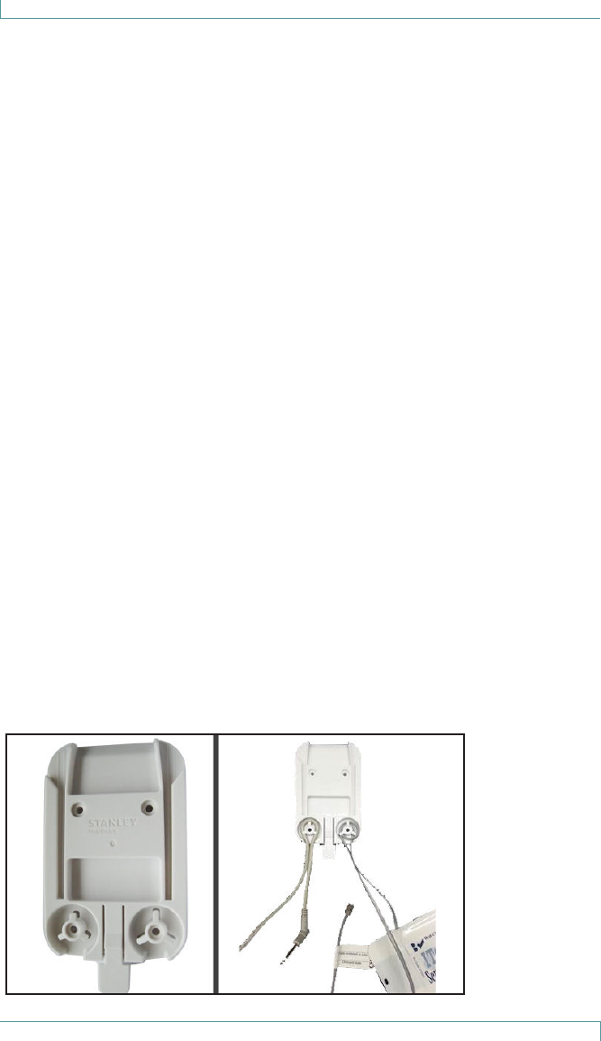
Strain Relief
Two strain relief mechanisms are built into the wall mounting bracket:

Monitor Mounting/Installation Options
M310 Fall Monitor – Setup & User Guide 15
These are designed to help prevent cables from disconnection or
breakage.
The left side is for the Nurse Call and power cables.
• It is designed to support both the power cord (diameter TBD) and
Nurse Call cable (0.2”) at the same time
• If only the power cord is used, 2-3 loops should be made to keep
the cord securely in place
• If only the Nurse Call cable is used, one loop is enough
The right side is for one or both pad cables.
• It is designed to support two corded pad cables at the same time
• If only one pad cable is used, 2-3 loops should be made to keep
the cable securely in place
Install power cord and Nurse Call and pad cables as illustrated.
Chair or Bed Footboard Mounting
To mount the monitor on a chair or on a bed footboard that are more
than 5/16” thick, you will need a large wire clip (0120-123).
1. Slide the wire clip into the slots on the back of the monitor.
2. Use the clip to attach the monitor securely to the back of the
chair, in a place that the patient/resident cannot easily reach.
3. Ensure that the monitor is clipped to the outside of the chair to
reduce any discomfort for the patient/resident (the monitor’s
speaker will be facing away from the patient/resident as well).
Interfacing with a Nurse Call System
The monitor can be used to trigger a Nurse Call system that works with
call button circuits that are either Normally Open (closing when the
call button is depressed), or Normally Closed (opening when the call
button is depressed).
If an active Nurse Call system is connected, a positive confirmation tone
will sound. The Nurse Call icon will flash yellow when the Nurse Call
cable is being connected or disconnected, when the monitor is set to
N.C. volume setting.
The monitor accepts a common ¼” mono plug that can be wired to a
Nurse Call system. The monitor will sound a beep if a Nurse Call jack is
inserted or removed while monitoring a patient/resident on the pad.

Monitor Mounting/Installation Options
16 M310 Fall Monitor – Setup & User Guide
If the Nurse Call jack needs to be adjusted while a patient/resident is
on the pad use the “Hold Mode” to allow this. When installing a Nurse
Call jack, we recommend using the wall mount bracket in the manner
shown, which provides cable restraint to help prevent accidental
unplugging of the jack. In order to provide proper cable restraint, the
cable (up to 0.25” in diameter) should be inserted before the monitor
is placed on the wall mount bracket. Any Nurse Call cable must be
located in such a way as to not pose a risk of strangulation.
If your Nurse Call system does not provide a compatible input or if you
want to wire a push button cord in parallel with the monitor, contact
your biomedical department to obtain the appropriate adapter. The
monitor does not have an input to allow a push button to be wired in
parallel.
If requesting information on interfacing the monitor to a Nurse Call
system, please have the following information available:
• The brand of your Nurse Call system
• A description of the system’s call cord or pillow speaker, including the
type of plug and number of pins in the plug
• Whether your Nurse Call system is Normally Open or Normally Closed
If this information is not available, you may still contact us for
assistance, and we will be glad to help you.

Monitor Mounting/Installation Options
M310 Fall Monitor – Setup & User Guide 17
Nurse Call Alarms
The Nurse Call jack can be used in all 3 Alarm volume settings (1, 2,
3, and NC). When a Nurse Call jack is plugged in and the monitor’s
alarm volume is set to “NC”, alarms are muted on the monitor. The
“NC” volume setting is treated as a 1 setting if no Nurse Call jack is
connected.
Note: An alarm sent to the Nurse Call system cannot be
cancelled from the monitor alone. After dealing with
the patient/resident according to your care policy, the
alarm must first be cancelled on the monitor, and then
at the Nurse Call system. Refer to the Nurse Call system
documentation for details on cancelling alarms at the
Nurse Call station.
Whether or not the volume setting is “NC”, the monitor sounds
a beep when the Nurse Call jack is inserted or removed while the
patient/resident is on the pad.
For more information on disabling the monitor, see “Hold Mode” on
page 9.

Summary of Audible Alerts and Tones
18 M310 Fall Monitor – Setup & User Guide
Summary of Audible Alerts and Tones
LED Tone Description
Reset Button LED – Alarm (Red)
Short flash every 0.6
seconds
Pad Exit
Alarm
patient/resident has left the bed or chair.
One long flash High-Low
Confirm
Monitor placed into Hold Mode
Reset Button LED – Status (Green) – Normal Operation
Long flash after Reset
button press, or long flash
once per minute
No Pad is communicating with monitor and a
patient/resident is on the pad
Short flash after Reset
button press
No Pad is communicating with the monitor,
but no one is on the pad
5 seconds rapid flashing
following an OFF to ON
pad status change, then
one long flash
No Rapid flashes indicate monitor is about to
start monitoring a patient/resident on a
pad. A pad exit during this period does not
trigger an alarm.
Long flash indicates monitor is now armed.
A pad exit triggers an alarm.
Two flashes every few sec-
onds and, after 1 minute, 1
flash every few seconds for
1 minute
No Monitor placed in Hold Mode to allow
patient/resident positioning or removal
Status LED (Yellow) – Status, Trouble, or Warning Conditions
Five short flashes repeated
every 2.4 seconds
Trouble
Alarm
Supervision failure
Monitor battery too low to operate
Equipment error
Three short flashes, then
1 long flash every 2.4
seconds
Trouble
Alarm
Nurse Call jack inserted or removed while
monitoring patient/resident on pad with-
out using Hold Mode (page 9). Press
the Reset button to mute the Alarm for 90
seconds, or reverse the jack change to stop
the Alarm.
One short flash per minute 2 Low Monitor low battery.
Continuous No Failed monitor power-up self-test or moni-
tor battery dying.
Three short flashes, the
2 long flashes every 2.4
seconds
Touble
Alarm
Cordless pad disconnected
Two short flashes per
minute
2 Low Cordless pad low battery

Maintenance
M310 Fall Monitor – Setup & User Guide 19
Maintenance
The monitor and the Sensormat pad may be cleaned with a damp cloth
or sponge using mild disinfectants. Never use alcohol, acidic or harsh
petroleum-based cleaners.
The monitor tolerates all EtO (ethylene oxide) gas sterilization
processes below 70ºC. Other types of gas sterilization are NOT to
be used on the monitor (e.g., formaldehyde, chlorine or hydrogen
peroxide). Do NOT sterilize the Sensormat pad.
To ensure maximum performance, follow these guidelines:
• Replace the Sensormat mat every 14 or 180 days (six months),
depending on the pad type.
• If maintenance or opening of the monitor is required, it should be
performed in a static-free environment by qualified personnel.
• Replace the batteries in the monitor upon low battery signal.
• Replace the batteries in the cordless pad transmitter upon low
battery signal.
• Perform regular checks on the monitors (status and connections).
Note: The Sensormat Pad is for single patient/resident use only.

System Specifications
20 M310 Fall Monitor – Setup & User Guide
System Specifications
Monitor Specications
Part Number FM-3100
Battery:
Type:
Typical Life:
Low Battery:
Three (3) CR123A Alkaline 3V, replaceable
1 year with typical use
7 days warning
Dimensions
(W x H x D)
Approx. 8.5 x 14.8 x 4.0 cm (3.4 x 5.70 x 1.65 in)
Weight Approx. 275 g or 9.70 oz (with batteries)
175 g or 6.17 oz (without batteries)
Operating Temp. 0 - 50 C
Relative
Humidity
5 - 90 % RH (non-condensing)
Mounting Wall, chair or bed footboard mountable
Built-in clip - objects up to 5/16” thick
Optional large wire clip - objects from 5/16” to 2¼” thick
Audible
Indicators
“LOW “ Minimum Level = 68dBA - at 1 foot from monitor
“HI” Maximum Level = 96dBA - at 1 foot from monitor
LED Indicators Alarm LED:
Red - Pad exit from an on-pad monitoring condition.
Status LED:
Yellow - Equipment trouble alerts
Green - Monitoring confirmation
Sensormat Pad Specications
Part Numbers ASDF: Tal to provide new numbers.
Dimensions
(W x H x D)
Chair pads: 42.1 x 0.7 x 34.8 cm (16 x 0.3 x 13.7 in)
Bed pads: 103.2 x 0.7 x 29.4 cm (40.7 x 0.7 x 11.6 in)
Weight Chair pads: 91 g (3.2 oz)
Bed pads : 205 g (7.2 oz)
Operating Temp. 10 - 40 C
Relative
Humidity
5 - 90 % RH (non-condensing), IP22
Mounting Placed on chair or bed as per usage instructions on pad

Regulatory Compliance
M310 Fall Monitor – Setup & User Guide 21
Regulatory Compliance
FCC/Industry Canada
This device has been tested and found to comply with the limits for
a Class B digital device, pursuant to Part 15 of the FCC Rules. These
limits are designed to provide reasonable protection against harmful
interference in residential installations. This equipment generates uses
and can radiate radio frequency energy and, if not installed and used
in accordance with the instructions, may cause harmful interference to
radio and television reception.
However, there is no guarantee that interference will not occur in
a particular installation. If this device does cause such interference,
which can be verified by turning the device off and on, the user is
encouraged to eliminate the interference by one or more of the
following measures:
• Re-orient or re-locate the receiving antenna.
• Increase the distance between the device and the receiver.
• Connect the device to an outlet on a circuit different from the one
that supplies power to the receiver.
• Consult the dealer or an experienced radio/TV technician.
WARNING: Changes or modifications to this unit not expressly
approved by the party responsible for compliance could
void the user’s authority to operate the equipment.
To comply with FCC Section 1.310 for human exposure to radio
frequency electromagnetic fields, implement the following instruction:
• A distance of at least 1.0 cm between the equipment and all
persons should be maintained during the operation of the
equipment.
This device complies with Part 15 of the FCC Rules and Industry Canada
licence-exempt RSS standard(s). Operation is subject to the following
two conditions: (1) this device may not cause interference, and (2) this
device must accept any interference, including interference that may
cause undesired operation of the device.
Le présent appareil est conforme aux FCC Part 15 et CNR d’Industrie
Canada applicables aux appareils radio exempts de licence.
L’exploitation est autorisée aux deux conditions suivantes : (1)
l’appareil ne doit pas produire de brouillage, et (2) l’utilisateur de

Regulatory Compliance
22 M310 Fall Monitor – Setup & User Guide
l’appareil doit accepter tout brouillage radioélectrique subi, même si le
brouillage est susceptible d’en compromettre le fonctionnement.
RoHS
RoHS Directive – 2002/95/EC

Warranty Information
M310 Fall Monitor – Setup & User Guide 23
Warranty Information
LIMITED WARRANTY: BED-CHECK® CONTROL UNITS
1. WARRANTOR:
This Limited Warranty is given by STANLEY Healthcare, 130 Turner Street, Waltham, MA 02453.
2. DURATION:
This Limited Warranty begins on the date the product is delivered to the purchaser and continues for a period
of two years (new units) or one year (refurbished units).
3. TO WHOM THIS LIMITED WARRANTY IS GIVEN:
This Limited Warranty is given to the original purchaser of Bed-Check’s products only.
4. PRODUCTS COVERED:
This Limited Warranty covers all Bed-Check Control Units. (i.e., Bed-Check Cordless, Model Vr, Classic-Check,
Chair-Check II, and Basic-Check)
5. WHAT IS COVERED UNDER THIS LIMITED WARRANTY:
Defects in material and workmanship which occur within the defined duration of this limited warranty.
Warrantor makes no other warranties expressed or implied, including without limitation, warrantor makes no
warranty as to merchantability or fitness for a particular purpose.
6. WHAT IS NOT COVERED UNDER THIS LIMITED WARRANTY:
a) ANY INCIDENTAL, INDIRECT, OR CONSEQUENTIAL LOSS, DAMAGE, OR EXPENSE THAT MAY RESULT FROM
ANY DEFECT, FAILURE, OR MALFUNCTION OF THE CONTROL UNITS.
b) ANY INCIDENTAL, INDIRECT, OR CONSEQUENTIAL LOSS, DAMAGE, OR EXPENSE THAT MAY RESULT FROM
USE OF THE CONTROL UNITS WITH ANOTHER MANUFACTURER’S PRESSURE SENSITIVE MAT, SENSING
DEVICE, OR OTHER FALL PREVENTION PRODUCT.
NOTE: SOME STATES DO NOT ALLOW THE EXCLUSION OR LIMITATION OF INCIDENTAL
OR CONSEQUENTIAL DAMAGES, SO THE ABOVE LIMITATIONS OR EXCLUSIONS MAY NOT
APPLY TO YOU.
c) Any defects or damage to the Control Units that may result from use of the Control Units with another
manufacturer’s parts, pressure sensitive mat, sensing device, or other fall prevention product.
d) Any failure that results from an accident, purchaser’s abuse, neglect or failure to operate the Control Units
in accordance with the instructions provided in the owner’s manual(s) supplied with the Control Units.
e) Any Control Units which have the serial numbers altered, defaced or removed.
f) Any Control Units which have been altered or modified in any way without the express written consent of
Bed-Check.
g) Any Control Units which have been repaired other than by Bed-Check.
7. RESPONSIBILITIES OF WARRANTOR UNDER THIS LIMITED WARRANTY:
a) In the event of a defect, malfunction, or other failure of the product not caused by any misuse or damage
to the product while in the possession of purchaser, the warrantor will remedy the failure or defect without
charge to the purchaser within a reasonable time. The remedy will consist of repair or replacement of the
product, or refund of the purchase price, at the warrantor’s option. If the product is no longer available, war-
rantor will supply purchaser with a comparable product or refund the purchase price at warrantor’s option.
However, the warrantor will not elect refund unless it is unable to provide replacement, and repair is not com-
mercially practicable and cannot be made within a reasonable time, or unless the purchaser is willing to accept
such refund.
b) If this product or one of its component parts contains a defect or malfunction, after a reasonable number
of attempts by the warrantor to remedy the defects or malfunctions, the purchaser will be entitled to either a
refund or replacement of the product or its component part or parts. Replacement of a component part
includes its free installation.
8. RESPONSIBILITIES OF THE PURCHASER UNDER THIS LIMITED WARRANTY:
a) Disinfect the Control Unit, if necessary, so that it is reasonably free from infectious matter.
b) Package the Control Unit with a minimum of two inches of shock absorbent packaging material.
Deliver or ship the Control Unit to:
STANLEY Healthcare, 130 Turner Street, Waltham, MA 02453. Freight costs, if any, must be borne by the
purchaser.
c) Use the Control Unit with reasonable care and in accordance with the supplied owner’s manual.
THIS LIMITED WARRANTY GIVES YOU SPECIFIC LEGAL RIGHTS AND YOU MAY ALSO
HAVE OTHER RIGHTS WHICH VARY FROM STATE TO STATE.

Warranty Information
24 M310 Fall Monitor – Setup & User Guide
LIMITED WARRANTY: BED-CHECK® SENSORMATS®
1. WARRANTOR:
This Limited Warranty is given by STANLEY Healthcare, 130 Turner Street, Waltham, MA 02453.
2. DURATION:
This Limited Warranty begins on the date the product is delivered to the purchaser and continues for a period
of one year or for the duration of the warranty stated on the Sensormat label from the date first installed,
whichever comes first.
3. TO WHOM THIS LIMITED WARRANTY IS GIVEN:
This Limited Warranty is given to the original purchaser of Bed-Check’s products only.
4. PRODUCTS COVERED:
This Limited Warranty covers all Bed-Check Sensormats.
5. WHAT IS COVERED UNDER THIS LIMITED WARRANTY:
Defects in material and workmanship which occur within the period described in paragraph 2. Warrantor
makes no other warranties expressed or implied, including without limitation, warrantor makes no warranty as
to merchantability or fitness for a particular purpose.
6. WHAT IS NOT COVERED UNDER THIS LIMITED WARRANTY:
a) ANY INCIDENTAL, INDIRECT, OR CONSEQUENTIAL LOSS, DAMAGE, OR EXPENSE THAT MAY RESULT FROM
ANY DEFECT, FAILURE, OR MALFUNCTION OF THE SENSORMAT ANY INCIDENTAL, INDIRECT, OR
CONSEQUENTIAL LOSS, DAMAGE, OR EXPENSE THAT MAY RESULT FROM USE OF THE SENSORMAT WITH
ANOTHER MANUFACTURER’S CONTROL UNIT OR OTHER FALL PREVENTION PRODUCT.
NOTE: SOME STATES DO NOT ALLOW THE EXCLUSION OR LIMITATION OF INCIDENTAL
OR CONSEQUENTIAL DAMAGES, SO THE ABOVE LIMITATIONS OR EXCLUSIONS MAY NOT
APPLY TO YOU.
b) Any defects or damage to the Sensormat that may result from use of the Sensormat with another manufac-
turer’s parts, control unit, or other fall prevention product.
c) Any failure that results from an accident, purchaser’s abuse, neglect or failure to operate the Sensormat in
accordance with the instructions provided on the Sensormat label.
d) Any Sensormat which has the serial numbers altered, defaced or removed.
e) Any Sensormat which has been altered or modified in any way without the express written consent of Bed-
Check.
f) Any Sensormat which has been repaired other than by Bed-Check.
7. RESPONSIBILITIES OF WARRANTOR UNDER THIS LIMITED WARRANTY:
a) In the event of a defect, malfunction, or other failure of the product not caused by any misuse or damage
to the product while in the possession of purchaser, the warrantor will remedy the failure or defect without
charge to the purchaser within a reasonable time. The remedy will consist of repair or replacement of the
product, or refund of the purchase price, at the warrantor’s option. If the product is no longer available, war-
rantor will supply purchaser with a comparable product or refund the purchase price at warrantor’s option.
However, the warrantor will not elect refund unless it is unable to provide replacement, and repair is not com-
mercially practicable and cannot be made within a reasonable time, or unless the purchaser is willing to accept
such refund.
b) If this product or one of its component parts contains a defect or malfunction, after a reasonable number
of attempts by the warrantor to remedy the defects or malfunctions, the purchaser will be entitled to either a
refund or replacement of the product or its component part or parts. Replacement of a component part
includes its free installation.
8. RESPONSIBILITIES OF THE PURCHASER UNDER THIS LIMITED WARRANTY:
a) Disinfect the Sensormat, if necessary, so that it is reasonably free from infectious matter.
b) Package the Sensormat unfolded and in a flat position. Deliver or ship the Sensormat to
STANLEY Healthcare, 130 Turner Street, Waltham, MA 02453. Freight costs, if any, must be borne by the
purchaser.
c) Use the Sensormat with reasonable care and in accordance with the supplied owner’s manual.
THIS LIMITED WARRANTY GIVES YOU SPECIFIC LEGAL RIGHTS AND YOU MAY ALSO
HAVE OTHER RIGHTS WHICH VARY FROM STATE TO STATE.

Warranty Information
M310 Fall Monitor – Setup & User Guide 25
Notes:

STANLEY InnerSpace
800-467-7224 SIS-Info@sbdinc.com
Doc 0980-182-000 Rev A - DRAFT. 30/04/2015
©2013 STANLEY Healthcare
www.StanleyHealthcare.com
STANLEY Healthcare +1-800-824-2996
©2015 STANLEY Healthcare. All rights reserved. 0980-182-000 Rev A - DRAFT
30/04/2015