AeroScout TED Tag/Exciter Deployment (TED) Tool TED-1000 User Manual Tag Exciter Deployment Device
AeroScout Tag/Exciter Deployment (TED) Tool TED-1000 Tag Exciter Deployment Device
User Manual

TAG/EXCITER DEPLOYMENT DEVICE
USER GUIDE
Draft3C

Disclaimer
The information and know-how included in this document are the exclusive property of STANLEY Healthcare and are intended
for the use of the addressee or the user alone. The addressees shall not forward to another their right of using the information,
know-how or document forwarded herewith, in whole or in part in all matters relating or stemming from or involved therein,
whether for consideration or without consideration, and shall not permit any third party to utilize the information, know-how
or the documents forwarded herewith or copies or duplicates thereof, unless at the company’s consent in advance and in
writing. Any distribution, advertisement, copying or duplication in any form whatsoever is absolutely prohibited. The Company
reserves the right to sue the addressee, user and/or any one on their behalves, as well as third parties, in respect to breaching its
rights pertaining to the intellectual rights in particular and its rights of whatever kind or type in the information, know-how or
the documents forwarded by them herewith in general, whether by act or by omission.
This document is confidential and proprietary to STANLEY Healthcare and is not to be distributed to any persons other than
licensed AeroScout Visibility System users or other persons appointed in writing by STANLEY Healthcare.
Trademark Acknowledgements
AeroScout is a trademark of Stanley Black & Decker, Inc. or its affiliates. Other brand products and service names are trademarks
or registered trademarks of their respective holders. Below is a partial listing of other trademarks or registered trademarks
referenced herein:
Cisco™ is a trademark of Cisco Systems, Inc.
Sun, Sun Microsystems, the Sun Logo, Java, JRE and all other Sun trademarks, logos, product names, service names, program
names and slogans that are referred to or displayed in this document are trademarks or registered trademarks of Sun
Microsystems, Inc. in the United States and other countries.
This product includes software developed by the Apache Software Foundation (http://www.apache.org/).
This product includes code licensed from RSA Data Security
Esper is a trademark of EsperTech, Inc.
Jboss is a trademark of Red Hat Middleware, LLC.
Oracle and Java are registered trademarks of Oracle and/or its affiliates. Other names may be trademarks of their respective
owners.
MS SQL Server 2005 and MS SQL Server 2008 are registered trademarks of Microsoft Corporation in the United States and/or
other countries.
JasperSoft, the JasperSoft Logo, JasperReports, the JasperReports logo, JasperIntelligence, JasperDecisions, JasperAnalysis, Scope
Center, Scope Designer, and JasperServer are trademarks or registered trademarks of JasperSoft, Inc. in the United States and
other countries.
Images of PLUM A+™, PLUM A+™ 3, LIFECARE PCA™, and SYMBIQ™ infusion systems are provided with permission of Hospira,
Inc. All rights reserved.
©2015 STANLEY Healthcare. All rights reserved. Doc: xxxx-xxx-xxx Rev A. Published: Draft 3C. KB Article: xxxx.

Tag/Exciter Deployment Device
User Guide 2
Table of Contents
Overview .............................................................................................................. 4
Model ................................................................................................................... 4
Prerequisites ......................................................................................................... 4
Accessories Included ............................................................................................ 4
TED Descriptions .................................................................................................. 5
TED Features ........................................................................................................ 6
TED Indications ..................................................................................................... 7
LED Indications ................................................................................................... 7
Buzzer Indications ............................................................................................... 9
Hardware Manager .............................................................................................. 9
Installing Hardware Manager ............................................................................. 10
Charging the TED Device ................................................................................... 11
Connecting TED via USB .................................................................................... 12
Connecting TED via Bluetooth® ......................................................................... 12
Pairing TED with a PC ........................................................................................ 12
Pairing TED with a Mobile Device ....................................................................... 13
Activating and Configuring Tags ...................................................................... 14
Connecting and Using Tag Manager .................................................................. 14
Connecting and Using Tag Manager BD ............................................................ 16
Detecting Exciters .............................................................................................. 18
Configuring the Exciter Detector Application...................................................... 18
How to Detect Exciters ...................................................................................... 22
Exciter Detection Messages ............................................................................... 23
Exporting and Clearing Messages ...................................................................... 25
Using the TED Device Manager Application ..................................................... 25
Viewing TED’s Connection Status ...................................................................... 26
Viewing TED’s Battery Status ............................................................................. 27
Viewing TED’s LED Status .................................................................................. 27
Updating TED’s Firmware .................................................................................. 28

Tag/Exciter Deployment Device
User Guide 3
Resetting the Device .......................................................................................... 29
Device Maintenance........................................................................................... 30
Battery .............................................................................................................. 30
Cleaning the Device .......................................................................................... 30
TED Accessories .................................................................................................. 31
TED Specifications .............................................................................................. 32
Safety, Warnings and Warranty ........................................................................ 33
Tag/Exciter Deployment Device
User Guide 4
Overview
The STANLEY Healthcare Tag/Exciter Deployment Device (TED) is a key
component of the STANLEY Healthcare’s visibility solution. The small portable
hand-held device, with rechargeable battery, is used to activate and configure
tags and measure the coverage of LF and US Exciters wirelessly.
TED connects directly to a PC via a USB cable or wirelessly using Bluetooth® to a
PC or mobile device. The TED device utilizes the Hardware Manager
Applications or mobile app to perform various tasks. Fast and easy activation,
configuration, testing, temperature calibration and battery initialization of
STANLEY Healthcare tags can be performed. Additionally TED configures, tunes,
and measures the coverage area of LF and US Exciters.
Model
• SKU: TED-1000
Prerequisites
The Hardware Manager Application must be installed prior to using the TED
device. See Hardware Manager.
Accessories Included
The following accessories are included with the TED device:
• Micro USB Cable 1.5 meters
• Cradle for mobile attachment
Tag/Exciter Deployment Device
User Guide 5
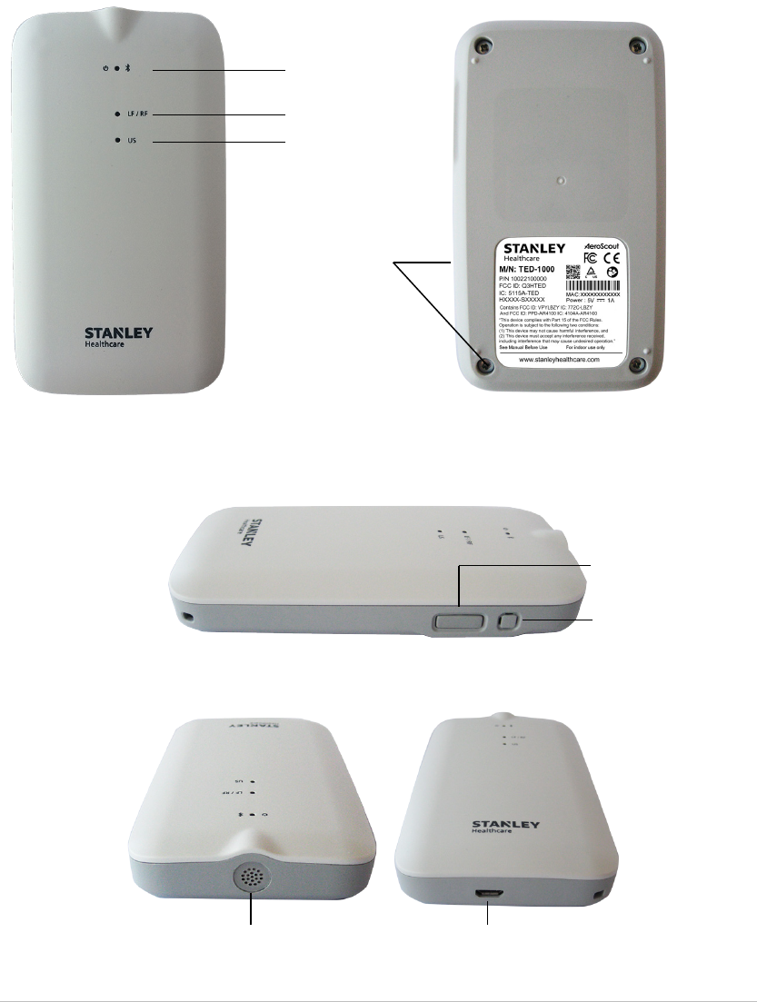
TED Descriptions
The following describes the parts of the TED device:
Front View
Side View
Rechargeable
battery casing
with screws
Back View
Top and Bottom View
Power and
Bluetooth® LED
LF and RF LED
US LED
Power and
Bluetooth®
On/Off Button
Buzzer for Audio
Indications
US Receiver
Micro USB Port

Tag/Exciter Deployment Device
User Guide 6
TED Features
Tag Activator
The TED device detects, activates and configures wirelessly up to 80 STANLEY
Healthcare tags simultaneously, including Bi-directional tags, using the
Hardware Manager’s Tag Manager or Tag Manager BD applications.
Tag Battery Tester
The device is able to quickly test tag batteries in the field, even in an
environment where a Wi-Fi infrastructure is nonexistent.
Tag Battery Initialization
After a tag battery replacement, the TED device can be used to reset tag battery
counters.
Tag Telemetry Data
The device is able to read tag humidity and temperature logs on the spot.
Exciter Detector
TED receives LF or Ultrasound (Gen 1 and Gen 2) messages transmitted by
Exciters. These messages are displayed using the Hardware Manager’s Exciter
Detector Application. Exciter coverage area, Bad LF, Bad US (Noise Mode) and
overlapping beams can then be evaluated.
LED and Audio Indications
TED includes 3 (three) multicolored LEDs and a buzzer for various status
indications.
Rechargeable Battery
TED contains a rechargeable battery that is easily charged by connecting the
device to a PC. The status of the battery can be viewed using the TED Device
Manager Application, which is part of the Hardware Manager Application.
Connect via Bluetooth®
TED uses Bluetooth® 4.0 to wirelessly connect to a PC or mobile device. The
device can then be controlled, wirelessly, using the Hardware Manager
applications on the PC or the TED mobile app.
Easy Attachment Options
The device can be worn around your neck using a lanyard or clipped on a belt
using the optional belt clip.
Tag/Exciter Deployment Device
User Guide 7
Micro USB Port
TED is supplied with a Micro USB cable used for PC connection and battery
charging. The device automatically turns On once connected and turns Off
when disconnected. USB drivers are automatically installed when TED is
connected to a PC.
Mobile App (Future)
A TED Mobile app for iOS and Android is available. See……..
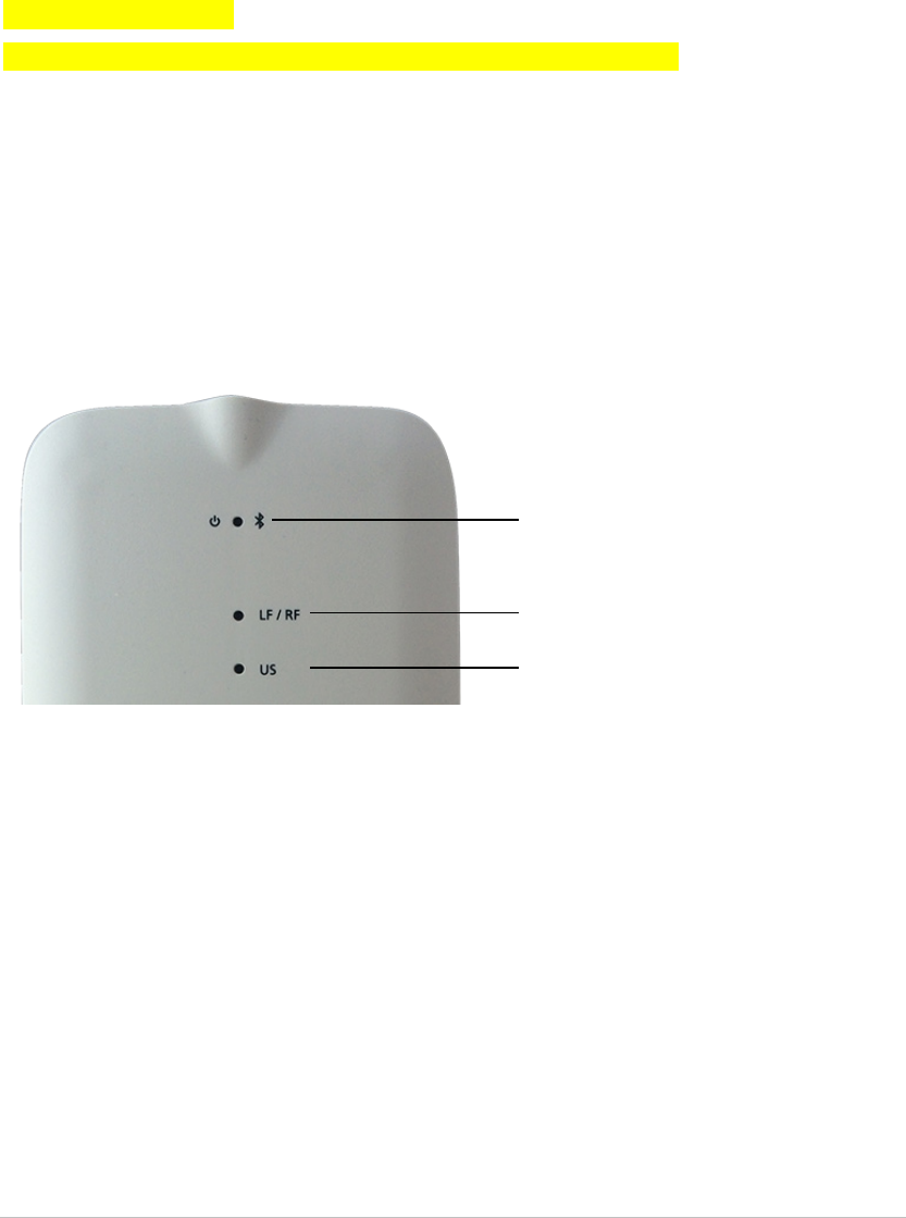
TED Indications
TED includes 3 (three) multicolored LEDs for visual indications and a buzzer for
audio indications.
LED Indications
The LEDs are located on the front of the TED device:
These indications are described in the table below.
The following symbols are used:
— = Solid color
- = Blink
Power and
Bluetooth® LED
LF / RF LED
US LED

Tag/Exciter Deployment Device
User Guide 8
Action Power / BT LED LF / RF LED US LED Comments
Power On 2 red blinks
(- -)
2 green blinks
(- -)
Simultaneous LED
blinking when
connected via USB.
Charging Solid red (—) When connected via
USB.
Battery Full Solid green (—) When connected via
USB.
Low Battery Blinking red
(- - - - - - ………)
Continuous blinking
No Battery Solid yellow (—) When connected via
USB
BT Pairing Blinking blue
(- - - - - - ………)
Continuous blinking
until Bluetooth
connection is
established.
BT Connected 5 blue blinks
(- - - - -)
After Bluetooth
connection is
established.
Receiving and
Transmitting
Blinking red
(- - - - - - ………)
During
communication with
tags.
LF Message Blinking green
(- - - - - - ………)
On receipt of LF
message.
Bad LF
Message
Blinking red
(- - - - - - ………)
On receipt of Bad LF
message.
Tag
Configuration
in process
Blinking yellow
(- - - - - - ………)
While tag
configuration is in
process.
US Message Blinking yellow
(- - - - - - ………)
On receipt of US
message
Noise Mode Blinking red
(- - - - - - ………)
Continuous blinking
during US Noise
Mode
Tag/Exciter Deployment Device
User Guide 9
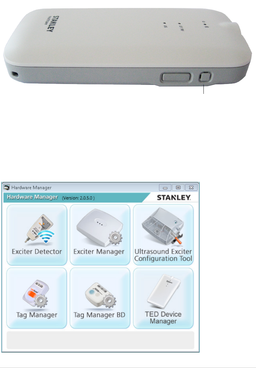
Buzzer Indications
The buzzer, for audio indications, is located on the side of the device:
Buzzer indications are described in the table below:
XXXXXXXXXXXXXXXXXXXXXXXXXXXXXXXXXXX
Hardware Manager
The Hardware Manager combines the suite of hardware configuration
applications into one platform, removing the need to download and install
separate applications.
Buzzer

Tag/Exciter Deployment Device
User Guide 10
TED utilizes the following Hardware Manager Applications:
• Tag Manager: Used to activate and configure the following tag families: T2,
T3, T4, T5, T6 and T7. For more information on the Tag Manager, please
refer to articles 2906 and 2907 in the STANLEY Healthcare Knowledgebase.
• Tag Manager BD: Used to activate and configure the communication
settings of STANLEY Healthcare Bi-directional Tags: T12 and T14. For more
information on the Tag Manager BD, please refer to article 6025 in the
STANLEY Healthcare Knowledgebase.
• Exciter Detector: Used to evaluate the range and coverage area of an
exciter. For more information on the Exciter Detector, please refer to article
1517 in the STANLEY Healthcare Knowledgebase.
• TED Device Manager: Used to view the current status of the TED device,
such as connection, battery and LEDs status. Additionally the application is
used to update TED’s firmware.
Installing Hardware Manager
Download and install the latest Hardware Manager Application:
• Hardware Manager Application Version 2 download, KB Article xxxx
• Hardware Manager Installation Guide, KB Article 2872
Tag/Exciter Deployment Device
User Guide 11
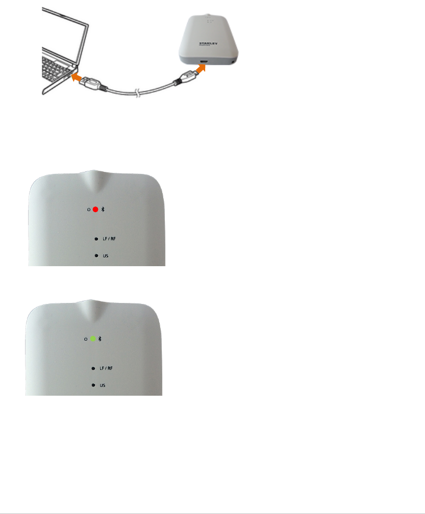
Charging the TED Device
The device is easily charged by connecting the supplied micro USB cable to a PC.
Connect TED to your computer using the supplied micro USB cable. 1.
Insert the smaller end of the cable to the micro USB port at the bottom
of the device.
Insert the USB end of the cable into an available USB port on your
computer.
Device drivers are automatically installed the first time the device is 2.
connected to a PC.
The device is charging when the Power/Bluetooth® LED is solid Red. 3.
Charging is complete when the Power/Bluetooth® LED is solid Green. 4.
Remove the micro USB cable from the Device and PC once charging is 5.
complete.
Tag/Exciter Deployment Device
User Guide 12
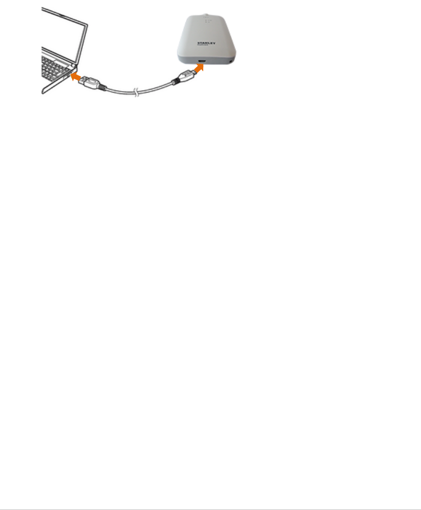
Connecting TED via USB
The TED device is connected directly to a PC using the supplied micro USB cable.
Connect TED to your computer using the supplied micro USB cable. 1.
Insert the smaller end of the cable to the micro USB port at the bottom
of the device.
Insert the USB end of the cable into an available USB port on your
computer.
Device drivers are automatically installed the first time the device is 2.
connected to a PC.
Connecting TED via Bluetooth®
TED can be connected, wirelessly, using Bluetooth® to a PC or mobile device.
Pairing TED with a PC
XXXXXXXXXXXXXXXXXXXXXX
Tag/Exciter Deployment Device
User Guide 13
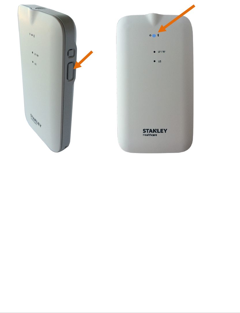
Pairing TED with a Mobile Device
Activate Bluetooth® on the mobile device. 1.
Turn On TED’s Bluetooth® mode by holding down the side button for 3 2.
seconds.
The device’s Bluetooth® LED starts blinking blue.
Select the TED device on the mobile device. 3.
Enter in the passcode: STANLEY1234. 4.
The device’s Bluetooth® LED stops blinking blue once the mobile device and 5.
the TED device are successfully paired.
Tag/Exciter Deployment Device
User Guide 14
Activating and Configuring Tags
The TED device detects, activates and configures wirelessly up to 80 STANLEY
Healthcare tags simultaneously, including Bi-directional tags.
The wireless tag management method consists of connecting TED to a PC or
mobile, and arranging the tags in range of the TED device.
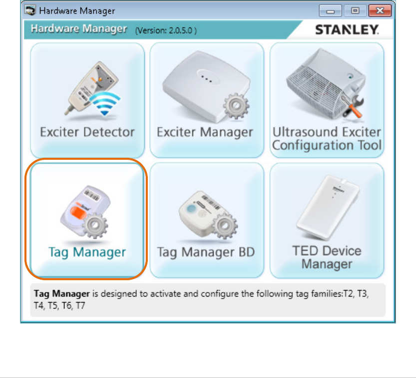
Connecting and Using Tag Manager
Before activating and configuring tags, the Tag Manager application must be
connected to the TED device.
Make sure the Hardware Manager Application is installed. See Installing 1.
Hardware Manager.
Connect the TED device to the PC using the Micro USB cable. 2.
Open the Hardware Manager Application. 3.
Click on Tag Manager. 4.
The Tag Manager application opens.
Tag/Exciter Deployment Device
User Guide 15
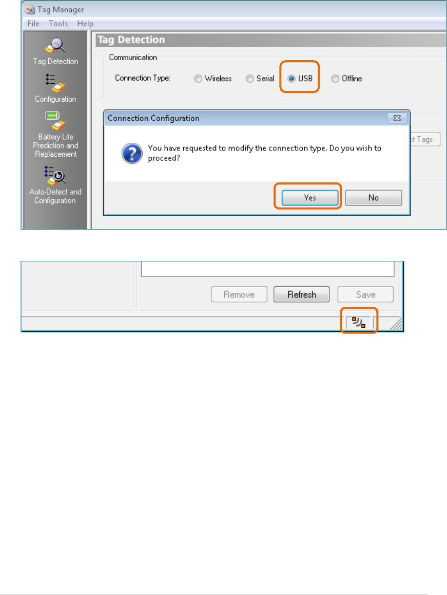
Under Communication select the USB Connection Type. 5.
A Connection Configuration message appears.
Click on Yes to proceed or No to cancel. 6.
Tag Manager is now connected to the TED device. 7.
Tag Manager supports all tags including T2 Tags, T3 flat Tags T4 application
Tags, T5 condition monitoring Tags and T6 GPS Tag. The procedure consists of
detecting the tags and then configuring them. Configuration options become
active and selectable according to the type of the tag.
For more information please refer to the Tag Manager User Guide, KB Article
2907.
Tag/Exciter Deployment Device
User Guide 16
Connecting and Using Tag Manager BD
Before activating and configuring tags, the Tag Manager BD application must
be connected to the TED device.
Make sure the Hardware Manager Application is installed. See Installing 1.
Hardware Manager.
Connect the TED device to the PC using the Micro USB cable. 2.
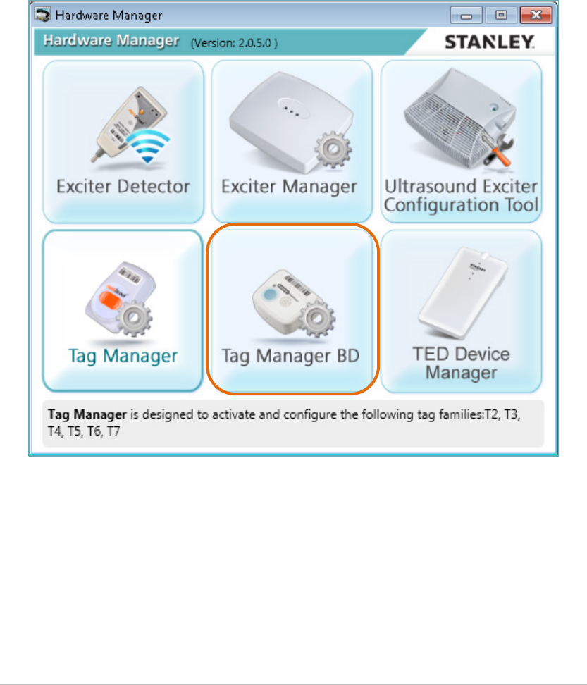
Open the Hardware Manager Application. 3.
Click on Tag Manager BD. 4.
The Tag Manager BD application opens.
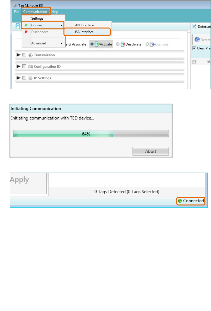
From the Menu bar click on Communication and select Connect ► USB 5.
Interface.
Tag/Exciter Deployment Device
User Guide 17
The Initializing Communication message appears.
Tag Manager BD is now connected to the TED device. 6.
Tag manager BD is designed to activate and configure STANLEY Bi-directional
Tags, such as the T12 and T14 Tags.
The procedure consists of detecting the tags and then configuring them.
Configuration options become active and selectable according to the type of
the tag.
For more information please refer to the Tag Manager BD User Guide, KB
Article 6025.

Tag/Exciter Deployment Device
User Guide 18
Detecting Exciters
TED receives LF or Ultrasound (Gen 1 and Gen 2) messages transmitted by
Exciters. These messages are displayed using the Hardware Manager’s Exciter
Detector Application. Exciter coverage area, Bad LF, Bad US (Noise Mode) and
overlapping beams can then be evaluated.
The Exciter Detector application also maintains a log of all incoming Exciter
messages. This file is created in the Exciter Detector installation directory.
Using TED to detect Exciters answers questions frequently asked by field
engineers:
• Does the Exciter cover all the area is it supposed to cover?
• Does the Exciter unnecessarily cover an area larger than the area is it
supposed to cover?
• Do the beams of multiple Exciters overlap?
• If they do, what is the extent of the overlapped area?
• Do ultrasound signals leak out the room?
Note
It is recommended to use the Detector Tag for more accurate Exciter
range and coverage measurement. See >>>>
Configuring the Exciter Detector Application
The Exciter Detector Application needs to be configured before usage.
Make sure the Hardware Manager Application is installed. See Installing 1.
Hardware Manager.
Connect the TED device to the PC using the Micro USB cable. 2.
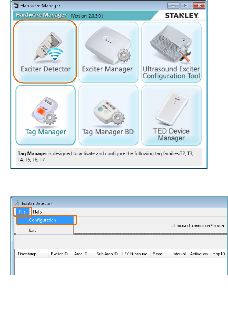
Open the Hardware Manager Application. 3.
Click on Exciter Detector. 4.
Tag/Exciter Deployment Device
User Guide 19
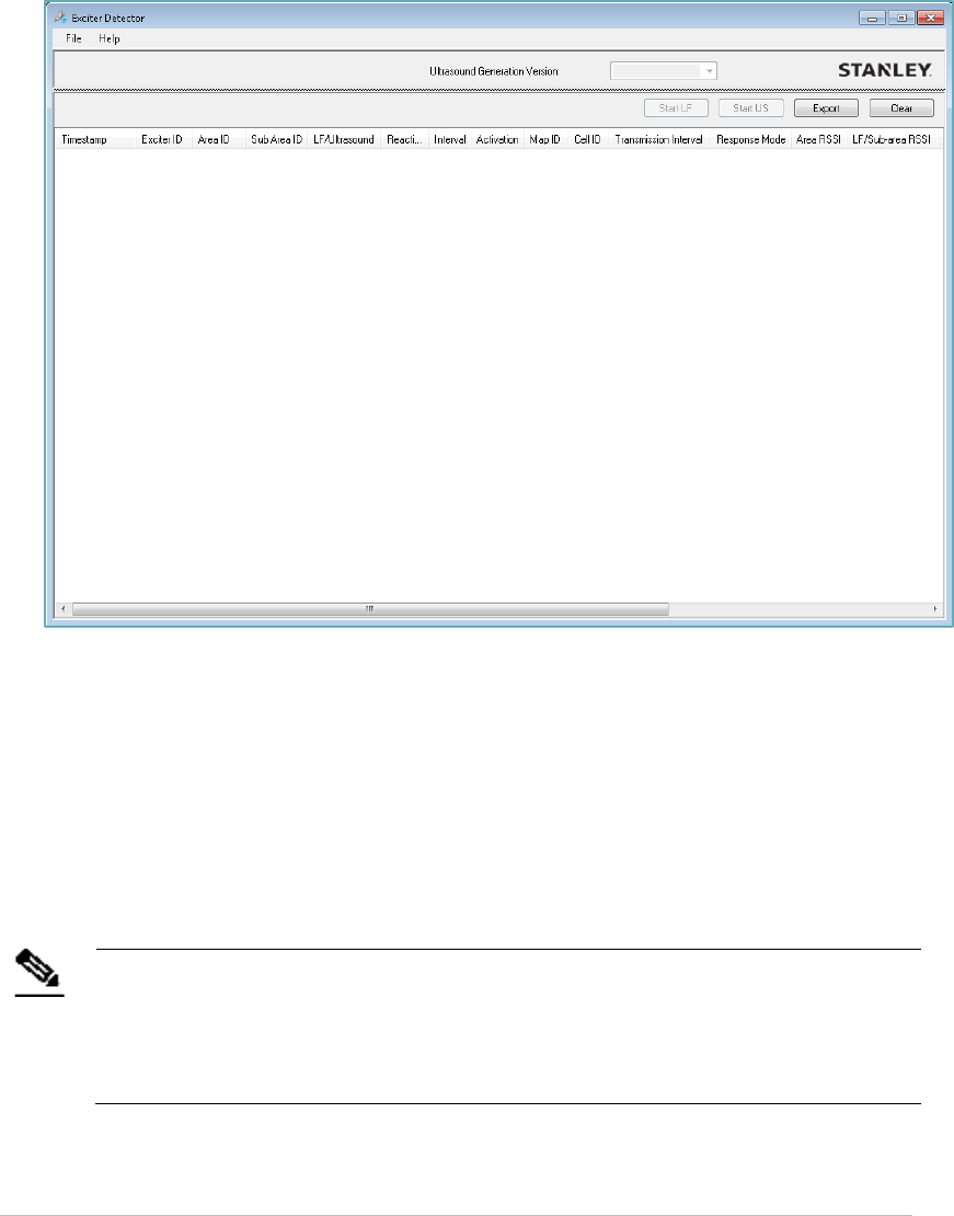
The Exciter Detector application opens.
From the Menu bar click on File and select Configuration. 5.
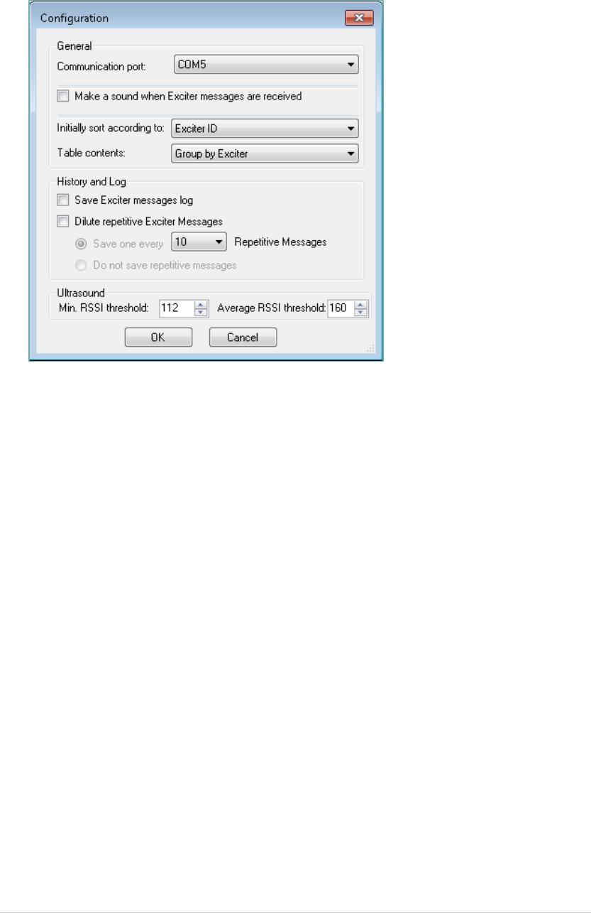
The Configuration dialog box opens.
Tag/Exciter Deployment Device
User Guide 20
Enter the following information: 6.
Communication Port
The device uses a Micro USB interface. Therefore, the port is a serial ‘COM’
port. By default, device communicates with the PC through the port shown
in this field. You can change the port, if the USB driver was installed on a
different port.
Make a sound when Exciter messages are received
Check this box to instruct the PC to emit a sound when receiving Exciter
messages through the device, in addition to the blinking of the device’s LED.
Initially sort according to
As the device receives messages, they appear on the Exciter Detector
application screen. You can select to sort the messages according to one of
the fields listed in this drop-down list.
Table contents
As Exciters transmit their messages at intervals measured in milliseconds,
large numbers of messages accumulate in a matter of seconds. Selecting the
Group by Exciter option reduces messages coming from the same Exciter to a
single message. In this case, you will see the detection process in the quickly
changing timestamp of the message. This grouping is useful when detecting
overlapping beams or when testing an area containing a large number of
Exciters. See How to Detect Exciters.
Select "Complete log" to display all messages.

Tag/Exciter Deployment Device
User Guide 21
Save Exciter messages log
Check this box to save all incoming messages to a log file. The file is created
in the Exciter Detector installation directory.
The log contains all the messages received in all sessions (it is not
overwritten).
Dilute repetitive Exciter messages
Often large numbers of messages contain identical information. The "dilute"
option allows you to consolidate several identical messages into one
message to save to the log (the constantly changing timestamp is excluded
from this analysis). If you select this option:
Select To
Save one every Specify the number of repetitive messages you
want to consolidate. Identical messages may still
be stored in the log if the consolidates messages
themselves are identical.
Do not save repetitive
messages
Save just one message and completely ignore all
repetitive messages. The next message that will
be stored will be one that contains different data.
Min. RSSI threshold
This parameter defines the threshold for a valid minimum RSSI indication. A
value below the threshold will appear in red. For Generation 2 Exciters, this
parameter represents the minimum for sub-area RSSI.
Average RSSI threshold
This parameter defines the threshold for a valid average RSSI indication. A
value below the threshold will appear in red. For Generation 2 Exciters, this
parameter represents the average for sub-area RSSI.
Click OK. 7.
Tag/Exciter Deployment Device
User Guide 22
How to Detect Exciters
Make sure TED is connected to the PC via the USB cable. 1.
From the Hardware Manager Application click on Exciter Detector. 2.
The Exciter Detector Application screen opens.
If necessary, change the configuration of Exciter Detector Application. See 3.
Configuring the Exciter Detector Application.
Click the Start button (when using LF, click the Start LF button. When using 4.
Ultrasound, press the Start US button. When using Noise Mode, press Start
Noise Mode).
The button changes to Stop.
The generation of the TED device is automatically be detected and displayed 5.
in Ultrasound Solution Version (generation 1 or generation 2).
Note
Generation 1 Exciter Detectors do not support Generation 2
Ultrasound Exciters.
Generation 2 Exciter Detectors do not support Generation 1
Ultrasound Exciters.
Move near the Exciter. 6.

Tag/Exciter Deployment Device
User Guide 23
When TED receives the LF or Ultrasound Exciter signals, the right or middle
LED’s start to blink and the Exciter messages begin to appear on the screen
at a rate equal to the transmission interval of the Exciter. The messages are
sorted and shown (in one group or as individual entries) according to the
configuration settings.
When the Exciter Detector enters the coverage area of multiple Exciters
(overlapping beams), multiple series of messages appear – one series for
each Exciter. The last received message appears against a yellow
background. If the messages are configured to appear as a single message,
you will see as many messages as the number of Exciters detected, with a
yellow stripe changing places and delivering a "blinking" effect, which
allows you a better visualization.
Click the Stop button to stop the detection process. 7.
Exciter Detection Messages
The messages that appear in the Exciter Detector application screen provide the
following information:
Name Description
Timestamp The date and time when the message was received.
Exciter ID The ID of the Exciter, in hex, 4 digits (leading zeros).
Area ID The Area ID of the Exciter in decimal format.
Sub Area ID The Sub-Area ID of the Exciter in decimal format.
LF/Ultrasound This column display whether the signal is LF or
Ultrasound.
Reaction The expected tag reaction. In case the expected reaction
is to send a stored message, the message number is
shown.
TInterval The estimated transmission interval of this Exciter. The
Manager remembers the shortest interval between two
reports from one Exciter. If only one report was
received from this Exciter the value will be blank.
Activation Whether the Exciter activates or deactivates the tag.
Map ID Whether the Exciter changes the MapID on the tags.
Cell ID Whether the Exciter changes the cell ID on the tags.

Tag/Exciter Deployment Device
User Guide 24
Name Description
Transmission
Interval
This parameter will indicate if the Exciter is configured
to change the tag's transmission interval or stop its
transmission. For example if the Exciter is programed to
modify the tag's transmission interval to 5 seconds for a
period of 10 seconds, the value in this field will be
"modify to 5s for 10s. If the Exciter is not configured to
modify the tag's transmission interval, meaning that the
tag will keep using its permanent transmission interval,
this will be indicated by the word "Perm" in this
column.
Response Mode Whether the Exciter changes the response mode of the
tag (can be "Wait, Ensure, PSEM"), And the relevant
interval.
Area RSSI For Generation 1 Ultrasound Exciters: This parameter is
not relevant.
For Generation 2 Ultrasound Exciters: Indicates the
received signal strength (in millivolts) of the 5 bits of
the US signal which represent an area.
Sub-area RSSI For Generation 1 Ultrasound Exciters: Indicates the
received signal strength (in millivolts) of the US signal.
For Generation 2 Ultrasound Exciters: Indicates the
received signal strength (in millivolts) of the 5 bits of
the US signal which represent a sub-area.
Min. US RSSI The minimum US RSSI measurement received up to this
point.
For Generation 2 this calculation is based on the Sub
Area column.
Avg. US RSSI The average of US RSSI measurements received up to
this point.
For Generation 2 this calculation is based on the Sub
Area column.
Battery Level For Generation 2 only – indicates the battery level of
the exciter (H – High / L - Low).
Transmission Mode Whether the Exciter changes the transmission mode of
the tag
Perimeter Whether the Exciter is perimeter (1) or not (-) (applies to
advanced CCX usage scenarios).
Category The category parameter transmitted by the Exciter.
Used for changing tag behavior in different scenarios
(for example, bay separation).
Tag/Exciter Deployment Device
User Guide 25
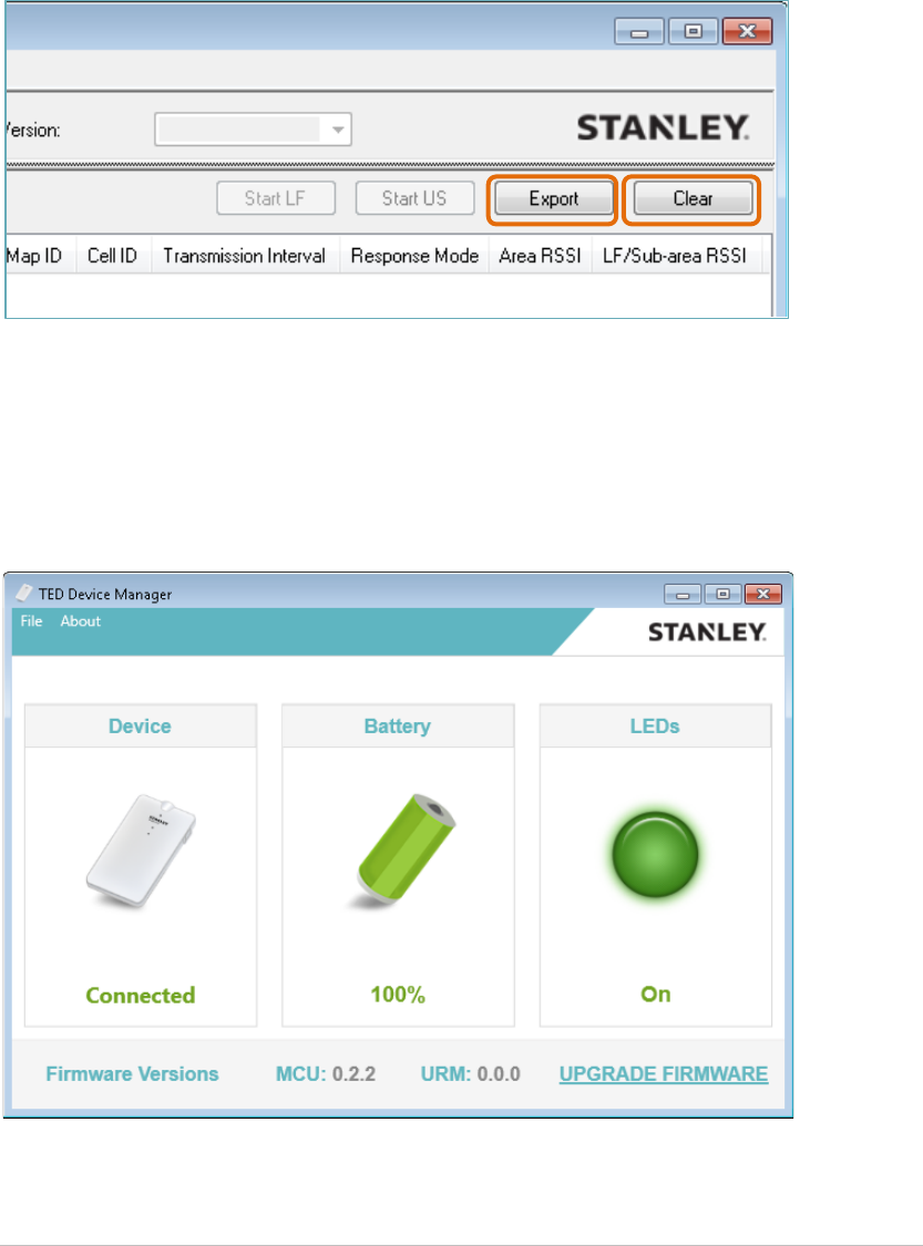
Exporting and Clearing Messages
Click the Export button to export the messages accumulated so far to a comma-
separate file.
Click the Clear button to clear the screen.
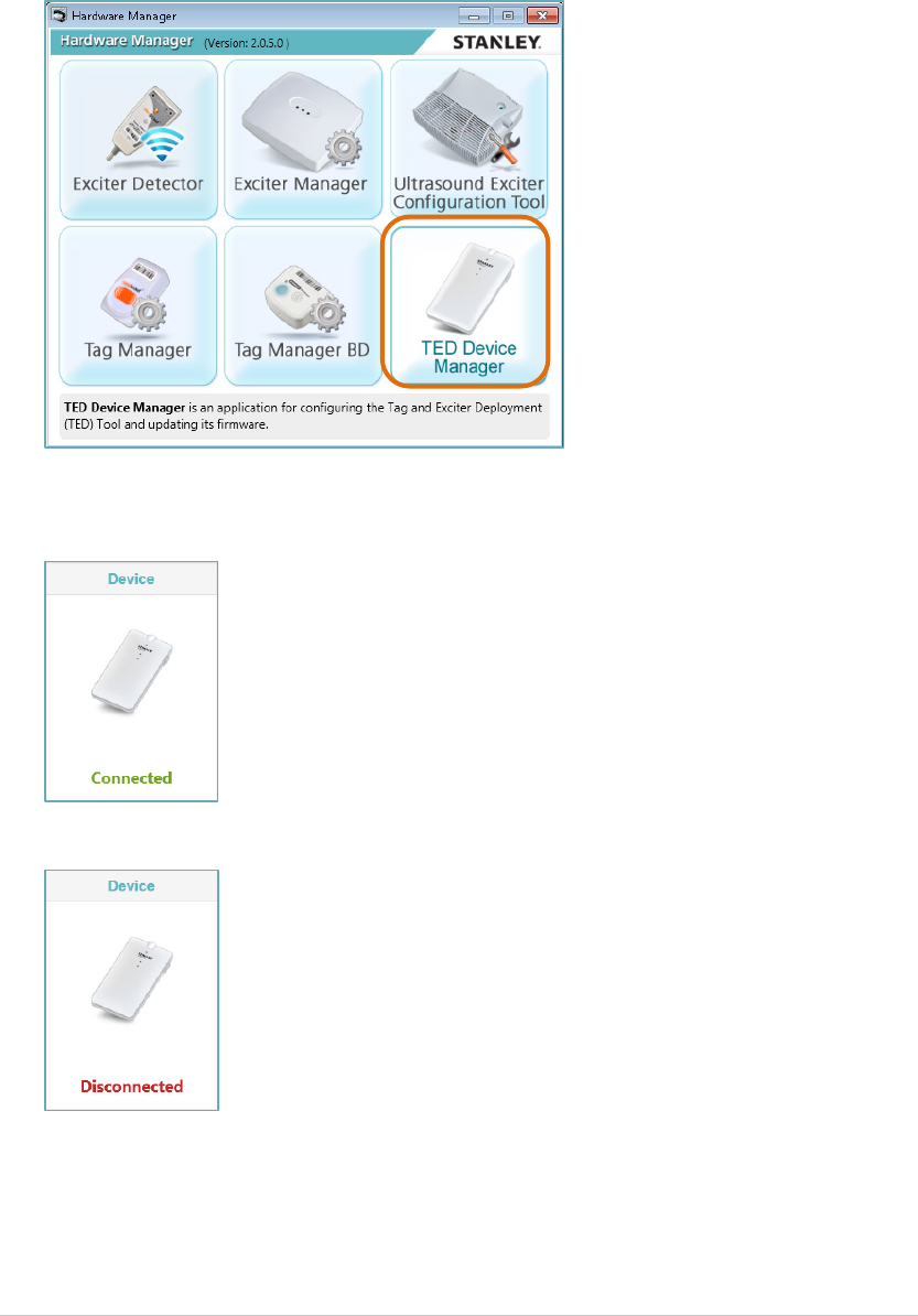
Using the TED Device Manager Application
The TED Device Manager Application, which is part of the Hardware Manager
Application, allows you to view the current status of the TED device.
Connection, battery, LEDs status and firmware version can be viewed. The
application is also used for updating TED’s firmware.
Tag/Exciter Deployment Device
User Guide 26
Viewing TED’s Connection Status
From the Hardware Manager Application click on TED Device Manager. 1.
The TED Device Manager screen opens
Connected is displayed if the device is connected. 2.
Disconnected is displayed if the device is disconnected.
Tag/Exciter Deployment Device
User Guide 27
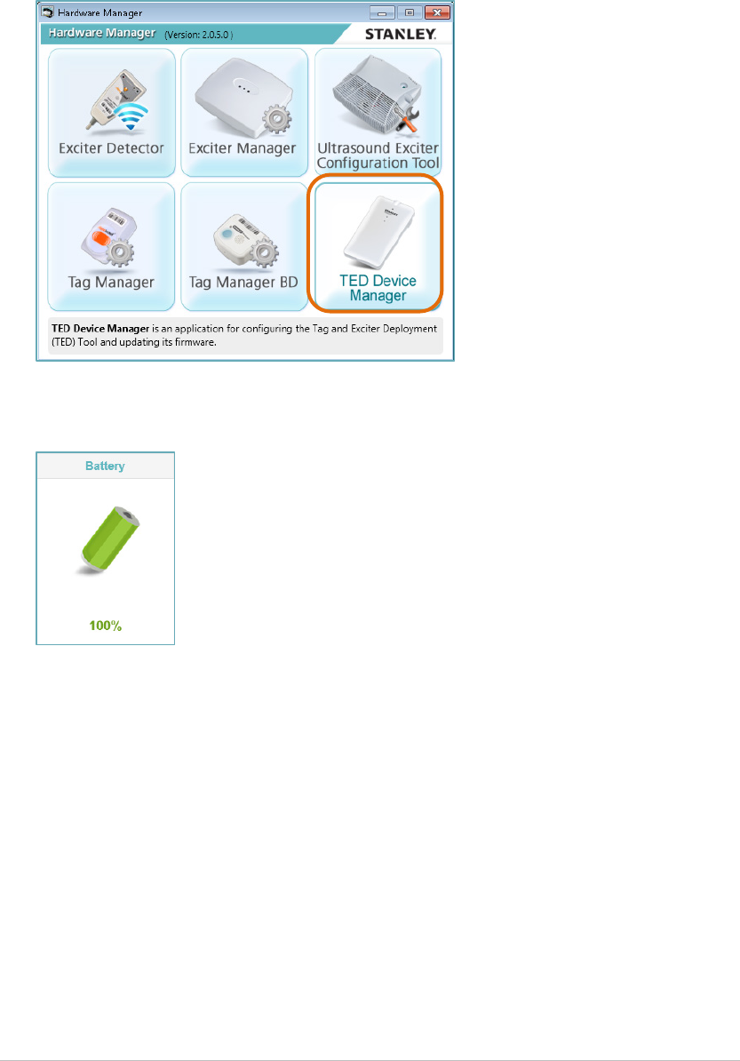
Viewing TED’s Battery Status
From the Hardware Manager Application click on TED Device Manager. 1.
The TED Device Manager screen opens.
TED’s current battery status is displayed. 2.
Viewing TED’s LED Status
XXXXXXXXXXXXXXXXXXXXXX
Tag/Exciter Deployment Device
User Guide 28
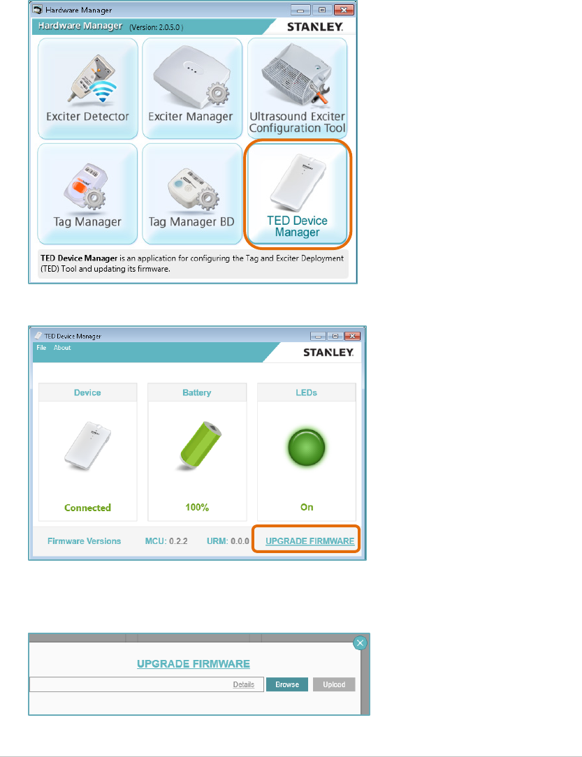
Updating TED’s Firmware
TED’s firmware is updated using the TED Device Manager Application, which is
part of the Hardware Manager Application.
Make sure TED is connected to the PC via the USB cable. 1.
From the Hardware Manager Application click on TED Device Manager. 2.
The TED Device Manager screen opens.
Click on UPGRADE FIRMWARE. 3.
Locate the latest firmware and then click on Upload. 4.

Tag/Exciter Deployment Device
User Guide 29
Resetting the Device
Tag/Exciter Deployment Device
User Guide 30
Device Maintenance
Battery
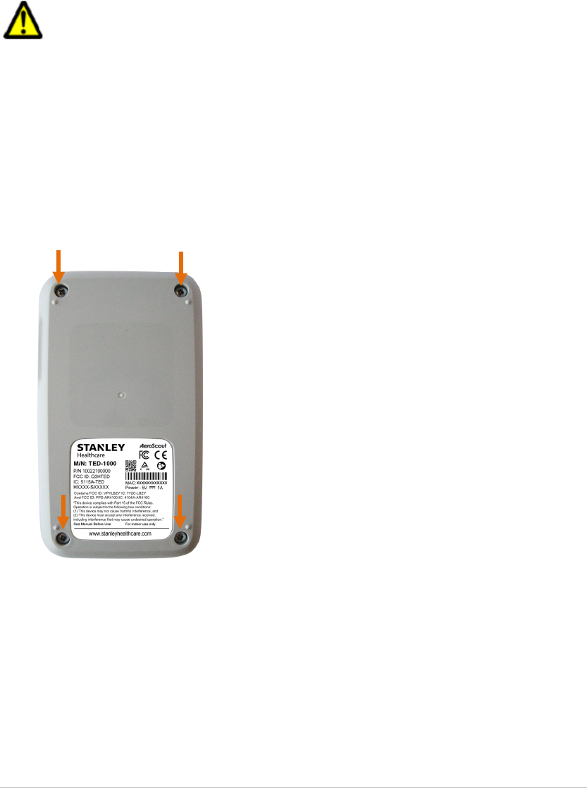
TED uses a rechargeable battery which can be replaced if needed.
CAUTIONS:
• RISK OF EXPLOSION IF BATTERY IS REPLACED BY AN
INCORRECT TYPE.
• DISPOSE OF USED BATTERIES ACCORDING TO THE
INSTRUCTIONS.
To replace the battery:
Remove the panel by unscrewing the 4 case screws. 1.
Remove the battery. 2.
Install a new and approved battery in the battery holder. 3.
Close and re-screw the panel. 4.
Cleaning the Device
Cleaning the device can be done using Alcohol or Chloride based wipers only.

Tag/Exciter Deployment Device
User Guide 31
TED Accessories
Accessory Model / KB Article
Micro USB Cable SKU: XXXX
Belt Clip Kit SKU: XXXX
Cradle for mobile SKU: XXXX
T2s Detector Tag SKU: TAG-2300-DT
Detector Tags Release Notes 8013
Detector Tags Quick Start Guide 7812
Tag Manager User Guide 2907
Tag Manager BD User Guide 6025
Tag Exciter Deployment Device Data Sheet XXXX
Tag Exciter Deployment Device Release Notes XXXX

Tag/Exciter Deployment Device
User Guide 32
TED Specifications
Performance
• Detection Range: Up to 3 meters
• Able to detect up to 80 tags in a single session
Physical and Mechanical
• Dimensions: 120mm x 68mm x 20mm (4.72in x 2.67in x 0.78in)
• Weight: 120g
Environmental Specifications
• Charging Temperature: 0°C to 45°C (32°F to +113°F)
• Operating Temperature: 0°C to 50°C (32°F to +122°F)
• Humidity: 0 to 95% RH non-condensing
• Ingress Protection Rating: IP-30
Electrical
• Micro USB Port
• Rechargeable Battery (Replaceable, if needed)
Radio
• Wi-Fi 802.11 (2.4 GHz); b/g/n compliant
• LF (Low Frequency Receiver 125kHz)
• Transmission power: up to +19dBm (~81mW)
• Bluetooth® 4.0
• US (Ultrasound Receiver 40KHz)
Security protocol
• WPA2 security with AES encryption
Audio
• Buzzer: Volume level 80dBA at 0.1 meter
Certification
• Radio: FCC Part 15, ETSI 300-328, 300-330, 301-489, RSS 210 (Canada),
IEC 6100 / EN 60601
• Safety: CE EN 60950, cTUVus UL 60950, IEC 60601

Tag/Exciter Deployment Device
User Guide 33
Safety, Warnings and Warranty
FCC STATEMENT
This equipment has been tested and found to comply with the limits for a Class B digital device,
pursuant to Part 15 of the FCC rules. These limits are designed to provide reasonable protection
against harmful interference in a residential installation. This equipment generates uses and can
radiate radio frequency energy and, if not installed and used in accordance with the instructions,
may cause harmful interference to radio communications. However, there is no guarantee that
interference will not occur in a particular installation. If this equipment does cause harmful
interference to radio or television reception, which can be determined by turning the equipment
off and on, the user is encouraged to try to correct the interference by one or more of the
following measures:
a) Reorient or relocate the receiving antenna.
b) Increase the separation between the equipment and receiver.
c) Connect the equipment to an outlet on a circuit different from that to which the receiver is
connected.
d) Consult the dealer or an experienced radio/TV technician.
Operation is subject to the following two conditions:
a) This device may not cause harmful interference
b) This device must accept any interference received, including interference that may cause
undesired operation.
FCC Warning
Modifications not expressly approved by the manufacturer could void the user authority to
operate the equipment under FCC Rules.
WARNING:
This device complies with Part 15 of the FCC Rules and RSS-210 of Industry and
Science Canada. Operation is subject to the following two conditions: (1) This device may not cause
harmful interference, and (2) this device must accept any interference received, including
interference that may cause undesired operation.
This device complies with Industry Canada license-exempt RSS standard(s). Operation is subject to
the following two conditions: (1) this device may not cause interference, and (2) this device must
accept any interference, including interference that may cause undesired operation of the device.
Le présent appareil est conforme aux CNR d'Industrie Canada applicables aux appareils radio
exempts de licence. L'exploitation est autorisée aux deux conditions suivantes : (1) l'appareil ne
doit pas produire de brouillage, et (2) l'utilisateur de l'appareil doit accepter tout brouillage
radioélectrique subi, même si le brouillage est susceptible d'en compromettre le fonctionnement.

Tag/Exciter Deployment Device
User Guide 34
STANLEY Healthcare (“STANLEY”) Standard Warranty and Disclaimer
For STANLEY Healthcare AeroScout® Products (“Products”)
Limited Warranty and Disclaimer. STANLEY warrants that commencing from the date of
delivery to Customer and continuing for a period of one (1) year thereafter (the “Warranty Period”), the
hardware components of STANLEY Healthcare AeroScout® Products (the “Hardware”) will be free from
defects in material and workmanship under normal use subject to the terms hereof. The date of
shipment of the Hardware by STANLEY is set forth on the packaging material in which the Hardware is
shipped. This limited warranty extends only to the original user of the Hardware. Customer's sole and
exclusive remedy and the entire liability of STANLEY and its suppliers under this limited warranty will
be, at STANLEY’s or its service center's option, shipment of replacement Hardware components within
the Warranty Period or a refund of the purchase price if the Hardware is returned to the party supplying
it to Customer, if different than STANLEY, freight and insurance prepaid. STANLEY replacement parts
used in Hardware repair may be new or equivalent to new, and STANLEY reserves the right to provide
replacement Hardware components of similar form and function, as long as the functionality is equal or
better than Customer’s original Hardware components. STANLEY’s obligations hereunder are
conditioned upon the return of affected Hardware in accordance with STANLEY’s then-current Return
Material Authorization (RMA) procedures. Notwithstanding the foregoing, the warranty for TAG
Hardware specifically designated for sterilization via autoclave or other sterilization methods shall have
a warranty period of 350 sterilization cycles from the date of delivery; provided, however, that
sterilization outside of environmental specifications approved in any applicable user documentation
voids all warranties.
Extended Warranty: STANLEY offers an extended warranty, for a fee, on AeroScout products.
Within the one (1) year of the standard warranty, additional warranty of two (2) years may be
purchased. Additional warranty years may only be purchased once within the first one (1) year, or prior
to warranty expiration. A maximum of three (3) total warranty years are available for Hardware.
Exclusions: The warranty set forth above will not apply if the Hardware or the Product (i) has
been altered, except by STANLEY, (ii) has not been installed, operated, repaired, or maintained in
accordance with instructions supplied by STANLEY, (iii) has been subjected to abnormal physical or
electrical stress, misuse, negligence, or accident; or (iv) is provided for beta, evaluation, testing, or
demonstration purposes for which STANLEY does not receive a payment of purchase price or license
fee.
In addition, this warranty shall not cover the following:
• Batteries (other than DOA -Dead On Arrival).
• Plastics (including defects in appearance, cosmetics, decorative or structural items including
framing and non-operative parts).
• Tag Calibration.
• Expenses related to removing or reinstalling the Products.
• Defects or damage that result from the use of Non-STANLEY certified Products, Accessories,
Software or other peripheral equipment.
• Defects or damages resulting from service, testing, adjustment, installation, maintenance,
alteration, or modification in any way by any party other than STANLEY, or its authorized
service partners.
• All software contained in or otherwise part of STANLEY Healthcare AeroScout®
Products, which is covered by STANLEY’s separate software warranty contained in the
separate software license agreement with respect to such Products.

Tag/Exciter Deployment Device
User Guide 35
The warranty set forth above shall not be enlarged and no obligation or liability shall arise out
of STANLEY’s rendering of technical advice, facilities or service in connection with Customer's
purchase of the STANLEY Healthcare AeroScout® Products.
Except for the foregoing warranties, which shall be the exclusive warranties with respect to any
Products, STANLEY MAKES NO WARRANTY OR REPRESENTATION OF ANY KIND, EXPRESS
OR IMPLIED, WRITTEN OR ORAL, REGARDING INFORMATION GIVEN OR THE PRODUCTS OR
SERVICES SUPPLIED AND EXPRESSLY DISCLAIMS ALL EXPRESS AND IMPLIED
WARRANTIES, REPRESENTATIONS AND CONDITIONS, INCLUDING WITHOUT LIMITATION ALL
WARRANTIES AND CONDITIONS OF QUALITY, NON-INFRINGEMENT, MERCHANTABILITY AND
SUITABILITY OR FITNESS FOR A PARTICULAR PURPOSE TO THE EXTENT PERMITTED BY
LAW. STANLEY WILL NOT BE LIABLE FOR CONSEQUENTIAL, INCIDENTAL, INDIRECT OR
PUNITIVE DAMAGES FOR ANY CAUSE OF ACTION, WHETHER IN CONTRACT, TORT OR
OTHERWISE. Consequential, incidental and indirect damages include, but are not limited to,
lost profits, lost revenue and loss of business opportunity, whether or not STANLEY was aware
or should have been aware of the possibility of these damages.

About STANLEY Healthcare
STANLEY Healthcare provides over 5,000 acute care hospitals and 12,000 long-term care organizations
with enterprise solutions that transform safety, security and operational efficiency. The STANLEY
Healthcare solution set enables customers to achieve organizational excellence and superior care in
five critical areas: Security & Protection, Safety, Environmental Monitoring, Clinical Operations &
Workflow, and Supply Chain & Asset Management. These solutions are complemented by consulting,
training, implementation and integration services. STANLEY Healthcare is proud to be part of Stanley
Black & Decker, Inc. For more information, visit: www.stanleyhealthcare.com
STANLEY Healthcare
130 Turner Street
Building 3
Waltham, MA 02453
Tel: +1-888-622-6992
North America
E-mail: stanleyhealthcare@sbdinc.com
Asia-Pacific
E-mail: stanleyhealthcare-asiapac@sbdinc.com
Europe
E-mail: shs-uk@sbdinc.com
Latin America
E-mail: stanleyhealthcare-latam@sbdinc.com
Middle East
E-mail: stanleyhealthcare-MEA@sbdinc.com