Aerohive Networks AP245 Access Point User Manual
Aerohive Networks, Inc. Access Point
User Manual
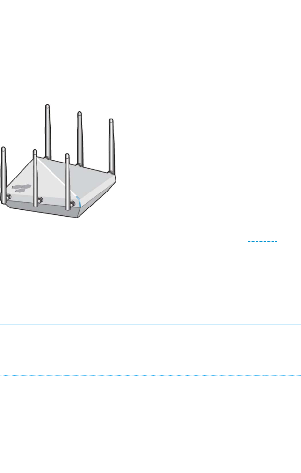
Aerohive AP245X Hardware User Guide
Read about and view specifications for the AP245X in this topic. Install the AP245X using this topic.
The AerohiveAP245X external-antenna AP features 802,11ac Wave 2 dual radio, 3x3:3 MU-MIMO with
data rates up to 1.3 Gbps per radio using existing 802.3af PoE infrastructure. Software-defined radio
allows ITmanagers to enable 802.11ac performance on both radios for the best coverage and
capacity Wi-Fi and investment protection. Built-in BLE provides proximity, indoor location tracking, and
other location-based mobile engagement services. The AP245X has the power to support enterprise-
grade features, including built-in application visibility and control, RADIUS authentication, DHCP, captive
web portals, location services and spectrum analysis.
For more information about Aerohive APs in general, see "Introduction to Aerohive APs"
Important! Changing the Country Code
If your access point is configured for the World Regulatory Domain, it is important to set the country
code to the country in which the APwill be deployed to meet regulatory requirements and for optimal
wireless operation. To do this, follow these steps:
For Devices Running HiveManager:
1. Power on the APand allow it to find and connect to HiveManager. Once the APisconnected, it
appears in the table of unconfigured devices on the Monitor > Devices page and is categorized as
New under the Management Status table header.
2. Select the check box for the AP, and then choose Update > Advanced >Update Country.
3. On the Update Country Code page, choose the appropriate country code from the drop-down
list, and then click Upload.
Page 1 of 1
7
AP245X Hardware User Guid
e
6
/
14
/
201
6

For Devices Running HiveManager NG:
1. Power on the AP and allow it to find and connect to HiveManager NG. Once the APis connected
it appears in the table of devices on the Monitor > Devices page.
2. Select the check box next to the AP, and then choose Assign Country Code from the Actions drop-
down list. In the dialog box that appears, select the appropriate country from the drop-down list
and then click Save.
3. Upload your changes to the device.
Regulatory Compliance Statements
The regulatory compliance statements in this section apply to Aerohive AP245X devices.
For Japan, the AP245X is restricted for indoor use in the 5150-5350 MHz band only.
Compliance Statements
The following compliance information applies to AP245X devices.
R&TTE and Low Voltage Directives
This device is compliant with the following directives:
• R&TTEDirective 1995/5/EC
• Low Voltage Directive 72/23/EEC
AP245X Compliance Statement - Europe
EU Declaration of Conformity
This device complies with the essential requirements of the R&TTE Directive 1999/5/EC. The
following test methods have been applied in order to prove presumption of conformity with the
essential requirements of the R&TTE Directive 1999/5/EC:
EN 60950-1:2009 2006+A2:2013
Safety of Information Technology Equipment
EN 62311: 2008 / Article 3(1)(a) and Article 2 2006/95/EC)
Assessment of electronic and electrical equipment related to human exposure restrictions for
electromagnetic fields (0 Hz-300 GHz)
EN 300 328 V1.9.1: 2015-02
Electromagnetic compatibility and Radio spectrum Matters (ERM); Wideband transmission
systems; Data transmission equipment operating using wide band modulation techniques;
Harmonized EN covering the essential requirements of article 3.2 of the R&TTE Directive
EN 301 893 V1.8.1: 2015-03
Broadband Radio Access Networks (BRAN); 5 GHz high performance RLAN; Harmonized EN
covering the essential requirements of article 3.2 of the R&TTE Directive
Page 2 of 1
7
AP245X Hardware User Guid
e
6
/
14
/
201
6

EN 301 489-1 V1.9.2: 2011
Electromagnetic compatibility and Radio spectrum Matters (ERM); Electromagnetic Compatibility
(EMC) standard for radio equipment and services; Part 1: Common technical requirements
EN 301 489-17 V2.2.1 2012
Electromagnetic compatibility and Radio spectrum Matters (ERM); Electromagnetic Compatibility
(EMC) standard for radio equipment; Part 17: Specific conditions for Broadband Data Transmission
Systems
In Italy the end-user should apply for a license at the national spectrum authorities in order to
obtain authorization to use the device for setting up outdoor radio links and/or for supplying
public access to telecommunications and/or network services.
•Česky [Czech]: [Aerohive] tímto prohlašuje, že tento [ AP245X] je ve shodě se základními
požadavky a dalšími příslušnými ustanoveními směrnice 1999/5/ES.
•Dansk [Danish]: Undertegnede [Aerohive] erklærer herved, at følgende udstyr [ AP245X]
overholder de væsentlige krav og øvrige relevante krav i direktiv 1999/5/EF.
•Deutsch [German]: Hiermit erklärt [Aerohive], dass sich das Gerät [AP245X] in
Übereinstimmung mit den grundlegenden Anforderungen und den übrigen einschlägigen
Bestimmungen der Richtlinie 1999/5/EG befindet.
•Eesti [Estonian]: Käesolevaga kinnitab [Aerohive] seadme [ AP245X] vastavust direktiivi
1999/5/EÜ põhinõuetele ja nimetatud direktiivist tulenevatele teistele asjakohastele sätetele.
•English: Hereby, [Aerohive], declares that this [ AP245X] is in compliance with the essential
requirements and other relevant provisions of Directive 1999/5/EC.
•Español [Spanish]: Por medio de la presente [Aerohive] declara que el [ AP245X] cumple
con los requisitos esenciales y cualesquiera otras disposiciones aplicables o exigibles de la
Directiva 1999/5/CE.
•Ελληνική [Greek]: ΜΕ ΤΗΝ ΠΑΡΟΥΣΑ [Aerohive] ΔΗΛΩΝΕΙ ΟΤΙ [ AP245X] ΣΥΜΜΟΡΦΩΝΕΤΑΙ
ΠΡΟΣ ΤΙΣ ΟΥΣΙΩΔΕΙΣ ΑΠΑΙΤΗΣΕΙΣ ΚΑΙ ΤΙΣ ΛΟΙΠΕΣ ΣΧΕΤΙΚΕΣ ΔΙΑΤΑΞΕΙΣ ΤΗΣ ΟΔΗΓΙΑΣ 1999/5/ΕΚ.
•Français [French]: Par la présente [Aerohive] déclare que l'appareil [AP245X] est conforme
aux exigences essentielles et aux autres dispositions pertinentes de la directive 1999/5/CE.
•Italiano [Italian]: Con la presente [Aerohive] dichiara che questo [ AP245X] è conforme ai
requisiti essenziali ed alle altre disposizioni pertinenti stabilite dalla direttiva 1999/5/CE.
•Latviski [Latvian]: Ar šo [Aerohive] deklarē, ka [ AP245X] atbilst Direktīvas 1999/5/EK
būtiskajām prasībām un citiem ar to saistītajiem noteikumiem.
•Lietuvių [Lithuanian]: Šiuo [Aerohive] deklaruoja, kad šis [ AP245X] atitinka esminius
reikalavimus ir kitas 1999/5/EB Direktyvos nuostatas.
•Nederlands [Dutch]: Hierbij verklaart [Aerohive] dat het toestel [ AP245X] in
overeenstemming is met de essentiële eisen en de andere relevante bepalingen van richtlijn
1999/5/EG.
•Malti [Maltese]: Hawnhekk, [Aerohive], jiddikjara li dan [AP245X] jikkonforma mal-ħtiġijiet
essenzjali u ma provvedimenti oħrajn relevanti li hemm fid-Dirrettiva 1999/5/EC.
•Magyar [Hungarian]: Alulírott, [Aerohive] nyilatkozom, hogy a [ AP245X] megfelel a
vonatkozó alapvetõ követelményeknek és az 1999/5/EC irányelv egyéb elõírásainak.
•Polski [Polish]: Niniejszym [Aerohive] oświadcza, że [ AP245X] jest zgodny z zasadniczymi
wymogami oraz pozostałymi stosownymi postanowieniami Dyrektywy 1999/5/EC.
•Português [Portuguese]: [Aerohive] declara que este [AP245X] está conforme com os
requisitos essenciais e outras disposições da Directiva 1999/5/CE.
Page 3 of 1
7
AP245X Hardware User Guid
e
6
/
14
/
201
6

•Slovensko [Slovenian
]
: [Aerohive] izjavlja, da je ta [ AP245X] v skladu z bistvenimi zahtevami
in ostalimi relevantnimi določili direktive 1999/5/ES.
•Slovensky [Slovak]: [Aerohive] týmto vyhlasuje, že [ AP245X] spĺňa základné požiadavky a
všetky príslušné ustanovenia Smernice 1999/5/ES.
•Suomi [Finnish]: [Aerohive] vakuuttaa täten että [AP245X] tyyppinen laite on direktiivin
1999/5/EY oleellisten vaatimusten ja sitä koskevien direktiivin muiden ehtojen mukainen.
EURadiation Warning Statement
To meet radiation exposure requirements, these devices should be installed at a minimum
distance of 9.05" (23 cm) from people or animals.
Federal Communication Commission Interference Statement
This equipment has been tested and found to comply with the limits for a Class B digital device,
pursuant to Part 15 of the FCC Rules. These limits are designed to provide reasonable protection
against harmful interference in a residential installation. This equipment generates, uses and can
radiate radio frequency energy and, if not installed and used in accordance with the instructions,
may cause harmful interference to radio communications. However, there is no guarantee that
interference will not occur in a particular installation. If this equipment does cause harmful
interference to radio or television reception, which can be determined by turning the equipment
off and on, the user is encouraged to try to correct the interference by one of the following
measures:
• Reorient or relocate the antenna of the receiving devices.
• Increase the separation between this equipment and receiving equipment.
• Connect this equipment into an outlet on a circuit different from that to which the receiving
equipment is connected.
• Consult the dealer or an experienced radio or TV technician for help.
FCC Caution: Any changes or modifications not expressly approved by the party responsible for
compliance could void the user's authority to operate this equipment.
This device complies with Part 15 of the FCC Rules. Operation is subject to the following two
conditions: (1) This device may not cause harmful interference, and (2) this device must accept
any interference received, including interference that may cause undesired operation.
IMPORTANT NOTE:
Radiation Exposure Statement:
This equipment complies with FCC radiation exposure limits set forth for an uncontrolled
environment. This equipment should be installed and operated with minimum distance 23 cm
between the radiator & your body.
This transmitter must not be co-located or operating in conjunction with any other antenna or
transmitter.
Country Code selection feature to be disabled for products marketed to the US/CANADA
Industry Canada Statement:
Page 4 of 1
7
AP245X Hardware User Guid
e
6
/
14
/
201
6
This device complies with Industry Canada license-exempt RSS standard(s). Operation is subject to
the following two conditions:

• This device may not cause interference, and
• This device must accept any interference, including interference that may cause undesired
operation of the device.
Le présent appareil est conforme aux CNR d'Industrie Canada applicables aux appareils radio
exempts de licence. L'exploitation est autorisée aux deux conditions suivantes :
• l'appareil ne doit pas produire de brouillage, et
• l'utilisateur de l'appareil doit accepter tout brouillage radioélectrique subi, même si le
brouillage est susceptible d'en compromettre le fonctionnement.
Caution:
(i) the device for operation in the band 5150-5250 MHz is only for indoor use to reduce the
potential for harmful interference to co-channel mobile satellite systems;
Avertissement:
(i) les dispositifs fonctionnant dans la bande 5150-5250 MHz sont réservés uniquement pour une
utilisation à l’intérieur afin de réduire les risques de brouillage préjudiciable aux systèmes de
satellites mobiles utilisant les mêmes canaux;
Radiation Exposure Statement:
This equipment complies with IC radiation exposure limits set forth for an uncontrolled
environment. This equipment should be installed and operated with minimum distance 32 cm
between the radiator & your body.
Déclaration d'exposition aux radiations:
Cet équipement est conforme aux limites d'exposition aux rayonnements IC établies pour un
environnement non contrôlé. Cet équipement doit être installé et utilisé avec un minimum de 32
cm de distance entre la source de rayonnement et votre corps.
Taiwan Compliance Information
Aerohive AP245X
第十二條→經型式認證合格之低功率射頻電機,非經許可,公司,商號或使用者均不得擅自變更頻率、加大
功率或變更原設計之特性及功能。
第十四條→低功率射頻電機之使用不得影響飛航安全及干擾合法通信;經發現有干擾現象時,應立即停用,
並改善至無干擾時方得繼續使用。
前項合法通信,指依電信法規定作業之無線電通信。 低功率射頻電機須忍受合法通信或工業、科學及醫療用
電波輻射性電機設備之干擾。
在 5.25-5.35 秭赫頻帶內操作之無線資訊傳輸設備,限於室內使用。
無線資訊傳設備的製造廠商應確保頻率穩定性,如依製造廠商使用手冊上所述正常操作,發射的信號應維持
於操作頻帶中。
Page 5 of 1
7
AP245X Hardware User Guid
e
6
/
14
/
201
6
Taiwan MPE Warning
電磁波曝露量MPE標準值(MPE) 1mW/cm2,送測產品實值為0.734 mW/cm2
Safety Guidelines
The information in this section applies to AP245X devices.
The following safety icons are used in these guidelines to identify the type of precaution:
This icon indicates a general caution. Failure to comply with a caution
notification can result in damage to equipment.
This icon indicates an electrical caution. Failure to comply with an electrical
notification can result in serious injury or death, and extensive damage to
equipment.
The following table lists the safety precautions you should follow when installing your
AP245X.
Aerohive devices must be installed by a professional installer who is certified to
install these types of devices and to ensure that they are properly grounded
and meet applicable local and national electrical codes.
These devices are intended for indoor use only.
Do not install the device in an environment where the operating ambient
temperature might exceed the recommended ranges.
Electrical equipment generates heat. Ambient air temperature may not be
adequate to cool equipment to acceptable operating temperatures without
adequate circulation. Be sure that the room where you install your device has
adequate air circulation.
Changes or modifications made to this device that are not expressly approved
by the party responsible for compliance could void the user's authority to
operate the equipment.
Electrostatic discharge (ESD) can damage equipment and impair electrical
circuitry. ESD damage occurs when electronic components are improperly
handled and can result in complete or intermittent failures. Be sure to follow
ESD-prevention procedures when handling electronic equipment and
components.
Never assume that power is disconnected from a circuit; always check the
circuit.
To meet radiation exposure requirements in all countries, these devices should
be installed at a minimum distance of 12.6" (32 cm) from people. See individual
country warning for country-specific distances, if required.
Page 6 of 1
7
AP245X Hardware User Guid
e
6
/
14
/
201
6

All Ethernet and RS232 (console) ports and the cables attached to them are
designed for intra-building connection to other equipment. Do not connect
these ports directly to wiring that exits the building where this appliance is
located
Installing the AP245X
The following sections describe how to install your Aerohive AP245X devices, connect them to the
network, and start managing them in HiveManager NG.
Shipping Carton Contents
The AP245X access point shipping carton contains the following items:
• AP245X chassis
• Aerohive Generic QuickStart Guide
• Hardware accessories kit containing:
• 3 wall-mount screws and three wall anchors
• Wall-mount or diagonal ceiling mounting bracket
Antennas are sold separately. (Aerohive SKU AH-ACC-DB-5-ANT-KIT, 6 dual-band 5 dBi articulated
indoor antennas)
Mounting the AP245X
You can mount the AP245X on a flat surface, a wall, or to the tracks of a dropped ceiling grid. The
following sections describe these installation methods.
Wall or Non-dropped Ceiling Mount
Attach the AP245X to any vertical or horizontal surface that will supports its weight (1.6 lb, or 0.73
kg), and to which you can install wall mount screws. Use the following procedure.
1. Use the bracket keyholes as a template to mark the mounting hole locations, and drill two
corresponding holes in the wall or drywall ceiling.
Page 7 of 1
7
AP245X Hardware User Guid
e
6
/
14
/
201
6
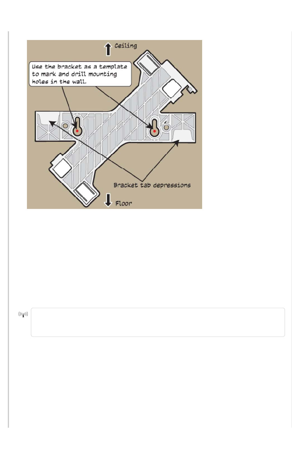
2. Install two wall mount screws (and plastic anchors if necessary). Leave the screw heads far
enough away from the wall so that the bracket will slip over them (you can test this using the
bracket). If you are connecting the device to cables from inside the wall, drill an access hole
in the wall for the cables, if necessary.
3. Attach the device to the bracket by lining up the mount tabs on the bottom of the device
with the corresponding mount tab depressions on the bracket (see illustration above). Slip the
device tabs under the edges of the bracket tab depressions and rotate the device until it
clicks into place on the bracket.
4. Mount the device on the wall or ceiling by slipping the bracket keyholes over the screw
heads and sliding the screws into the narrow part of the keyhole.
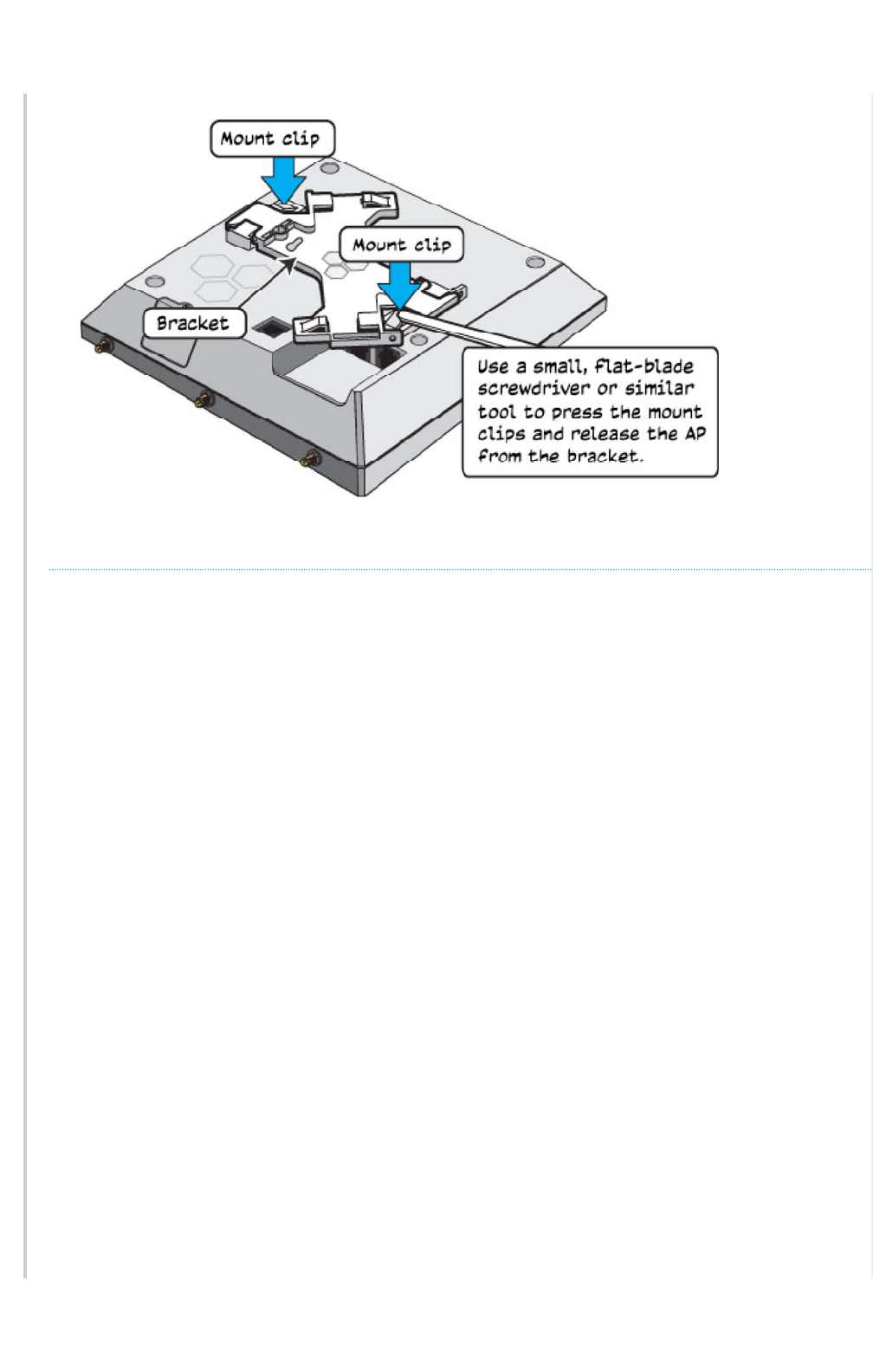
To remove the device from the bracket, use a small flat-blade screwdriver or similar tool
to depress the mount clips on the bottom of the device and release it from the bracket,
as shown in the illustration.
Page 8 of 1
7
AP245X Hardware User Guid
e
6
/
14
/
201
6
Dropped Ceiling Track Mount
You can mount the AP245X in either a square or diagonal position on a standard 15/16"-wide
track (2.38 cm) in a dropped ceiling. A diagonal mount requires the diagonal mount bracket that
ships with the device. This section describes how to do both installations.
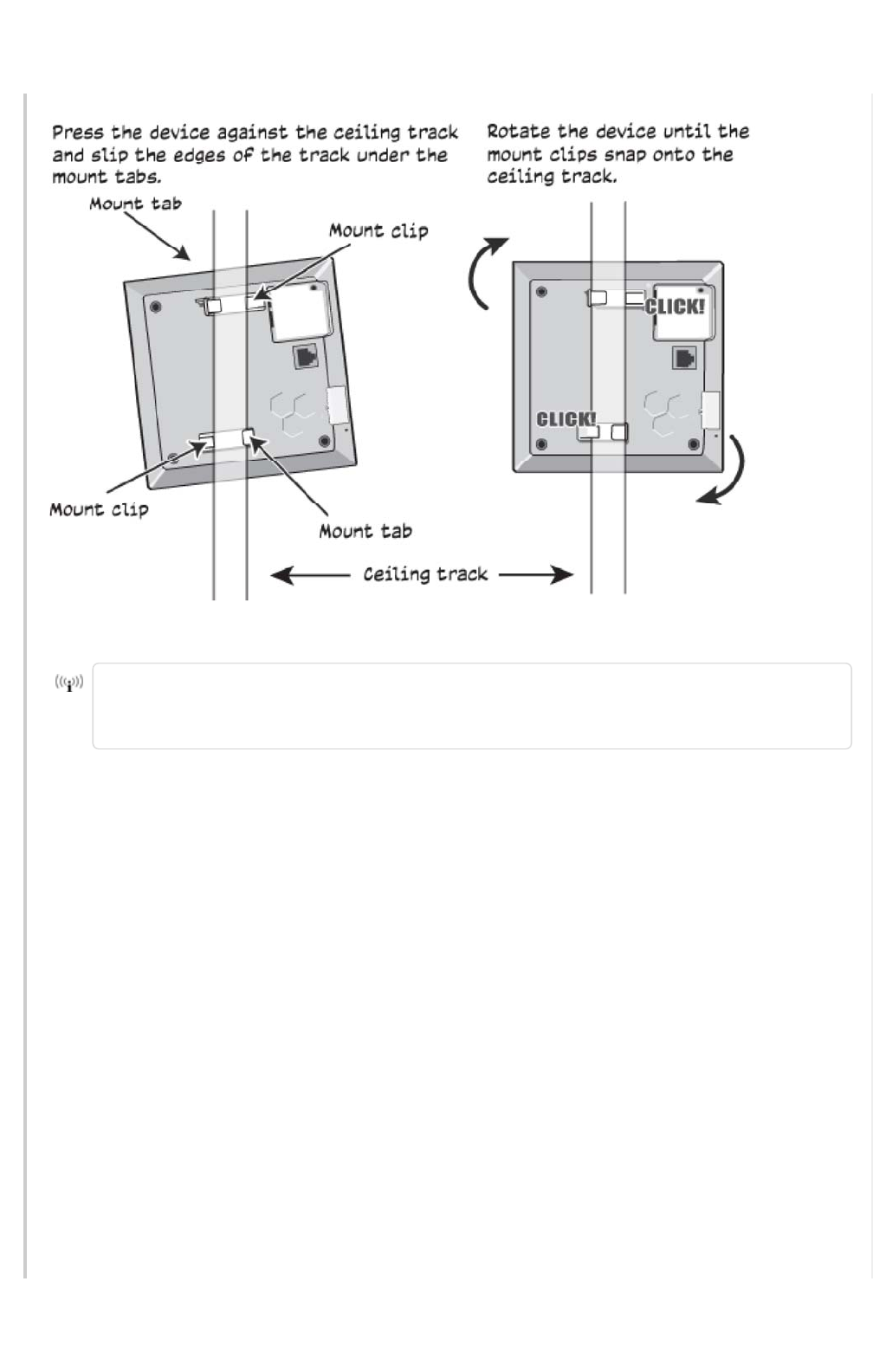
Square Dropped Ceiling Track Mount
Slip the mount tabs over the edges of the ceiling track as shown in the illustration, then rotate the
device slightly until the mount clips click into place over the track edges.
Page 9 of 1
7
AP245X Hardware User Guid
e
6
/
14
/
201
6
You can also mount these devices to non-standard or recessed dropped ceiling tracks
using brackets designed for 9/16" (1.34 cm) tracks. These brackets can be ordered from
Aerohive (AH- ACC-BKT-80211AC-KIT).
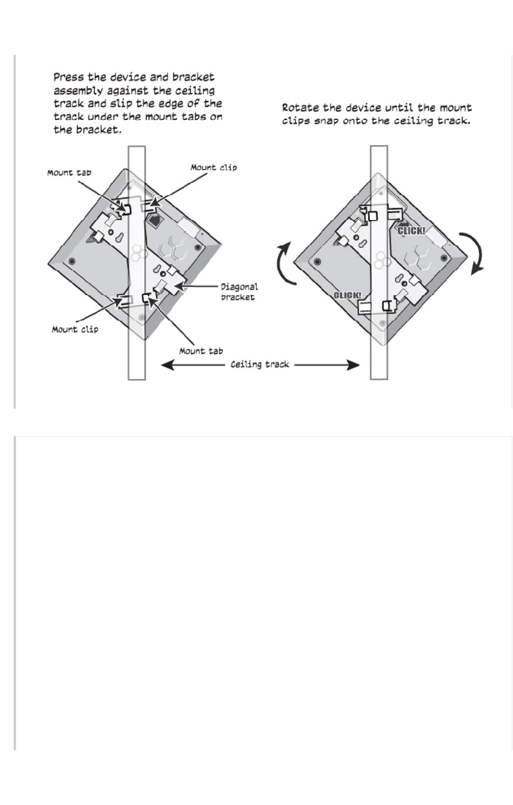
Diagonal Dropped Ceiling Track Mount
Follow these steps and the illustration to mount an AP245X in the diagonal position on a standard
dropped ceiling track.
1. Attach the diagonal bracket to the device by slipping the mount tabs on the device over
the plain edges of the diagonal bracket.
2. Rotate the bracket until the mount clips on the device click into place over the bracket
edge.
3. Hold the device upside down and slip the mount clips on the diagonal bracket over the
edges of the ceiling track. Because you are installing the device from below, it is helpful to
use your fingertips to identify the location of the mounting tabs by touch.
4. Press the device gently against the track and rotate it until the mount clips click into place.
Page 10 of 1
7
AP245X Hardware User Guid
e
6
/
14
/
201
6
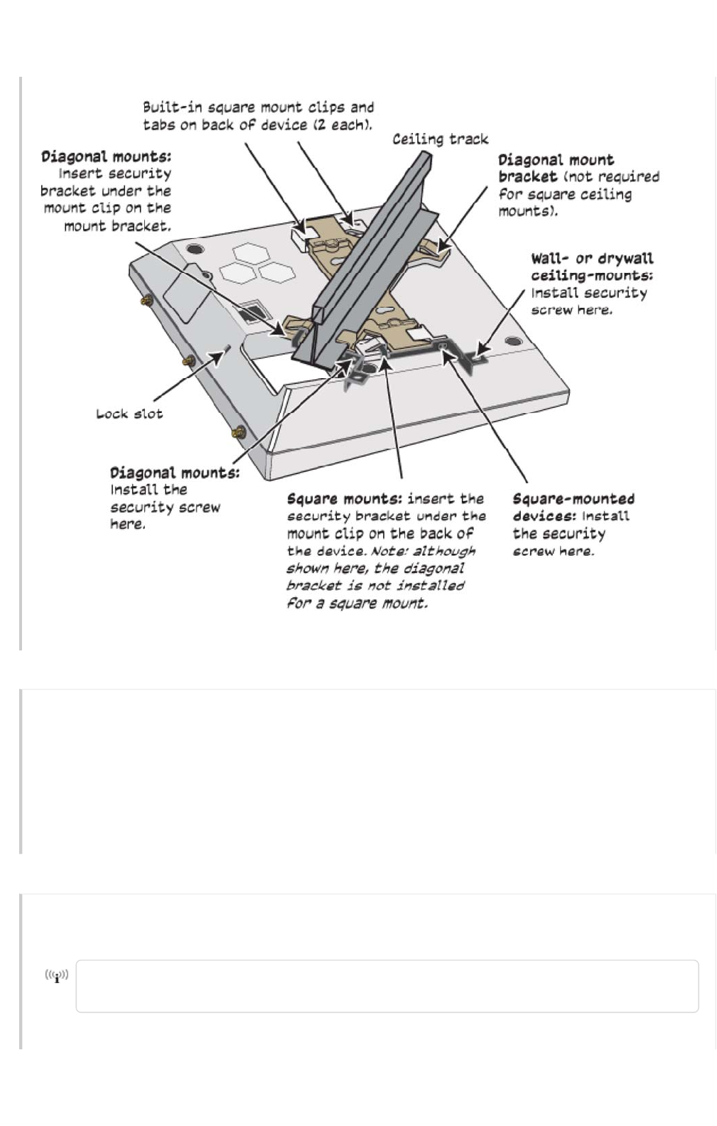
Securing the AP245X
You can secure the AP using a Kensington ® lock in the lock slot on the side of the device, or you
can order a security bracket kit (AH-ACC-SEC-KIT-80211AC) to secure it to a ceiling track or to a
wall, as shown in the illustration below. For more information, contact your Aerohive sales
representative.
Page 11 of 1
7
AP245X Hardware User Guid
e
6
/
14
/
201
6
Connecting the AP245X
Follow these steps to connect your AP245X to power and to the network.
1. Connect a standard RJ45 Ethernet cable from ETH0 on the APto a switch that provides PoE
power, or use a PoE injector (see "Ethernet Ports").
2. After the AP receives power, it automatically tries to get network settings and contact your
HiveManager management platform. This process takes about five minutes. When you see
the APlisted on the Devices page in the Monitor section of the management GUI, the initial
setup is complete and you can begin managing the AP.
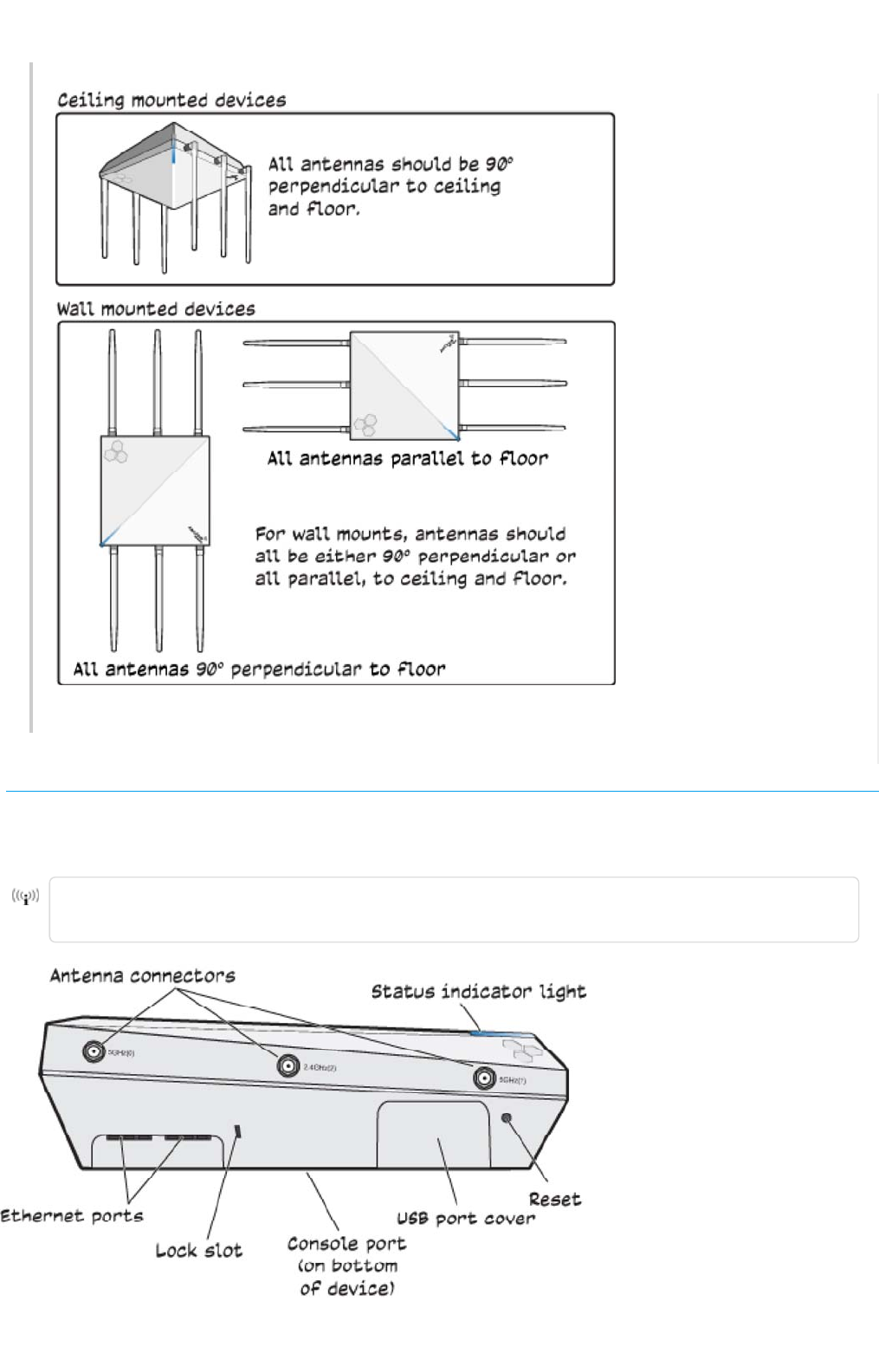
Antenna Alignment
For optimum reception, align the antennas as shown below, depending on how the device is
mounted.
Leave at least 12" (30 cm) of space around the antennas that is clear of any large metal
objects. Metal can distort antenna reception.
Page 1
2
of 1
7
AP245X Hardware User Guid
e
6
/
14
/
201
6
Hardware Components
You can see the hardware components of the AP245X in the illustration below and read about them in
the sections that follow.
To meet federal radiation exposure requirements, these devices should be installed at a
minimum distance of 9.05" (23 cm) from your body.
Page 1
3
of 1
7
AP245X Hardware User Guid
e
6
/
14
/
201
6

Hardware Component Descriptions
Status Light
The status light conveys operational states for system power, firmware updates, Ethernet and
wireless interface activity, and major alarms. The AP245X has a rectangular status light bar on the
top corner and down one side of the chassis. The colors of this light bar indicate the following
states of activity:
Dark: There is no power or the status indicator is disabled.
Amber (flashing): This is an alert that indicates that the device is performing a firmware
upgrade. Do not power off the device during this process.
Amber (steady): This is an alert that indicates that the CAPWAP connection has not been
successfully established, or the device is booting or shutting down.
White: The device is powered on, a successful CAPWAP connection has been made, and the
firmware is operating normally. During normal operation, the LED produces a slow blink
consisting of 4 seconds of illumination followed by one minute of darkness. To extend the life of
the status LED, turn it off completely for normal use, and turn it on when needed for
troubleshooting. To turn the LED off, establish a console connection with the device and enter
the following CLI command:
system led brightness off
To turn the LEDon and select the level of brightness, enter the following CLIcommand:
system led brightness [bright | soft | dim]
Console Port
The Console port is located on the bottom of the device. Use this port to make a serial connection
between your management system and the AP. The management station from which you
connect to the device must have a VT100 emulation program, such as Tera Term Pro © (a free
Page 1
4
of 1
7
AP245X Hardware User Guid
e
6
/
14
/
201
6
terminal emulator) or Hilgraeve HyperTerminal ® (provided with Windows ® operating systems
from XP forward). The serial connection settings are: 9600 bits per second, 8 data bits, no parity, 1
stop bit, no flow control.
The pin-to-signal mapping for the Console port is shown in "Aerohive Device Pin Assignments".

Ethernet Ports
The AP245X has two RJ45 10/100/1000Base-T/TX Ethernet ports (ETH0 and ETH1) that automatically
negotiate half- and full-duplex connections with the connecting device. The ports are
autosensing and adjust to straight-through and crossover standard Cat3, Cat5, Cat5e, or Cat6
Ethernet cables automatically. The APs receive power through an Ethernet connection to the
ETH0 port from PSE (power sourcing equipment) that is compatible with the 802.3at and 802.3af
standards.
PSE can be embedded in a switch or router, or it can come from purpose-built devices that inject
power into the Ethernet line en route to the AP. Because the PoE ports have autosensing
capabilities, the wiring termination in the Ethernet cable can be either straight-through or
crossover.
You can purchase your own PoE injector or purchase the following 20 W and 30 W PoE injectors as
optional accessories from Aerohive (not available in Brazil):
• AH-ACC-INJ-20W-EU
• AH-ACC-INJ-30W-EU
•AH-ACC-INJ-20W-US
•AH-ACC-INJ-30W-US
• AH-ACC-INJ-20W-AU
• AH-ACC-INJ-30W-AU
•AH-ACC-INJ-20W-IL
•AH-ACC-INJ-30W-IL
Reset Button
Use the Reset button to reset the device or restore the factory default settings. Insert a paper clip
or similar tool into the Reset pinhole and press the button. To reboot the device, press the button
for 5 seconds. To return the configuration to the factory default settings, press it for at least 10
seconds. After releasing the button, the indicator light goes dark, and then glows steady amber
while the firmware loads and the system performs a self-test. After the software finishes loading
and the AP has connected to the HiveManager management system, the status indicator glows
steady white.
To disable the reset button from resetting the configuration, enter this command: no reset-
button reset-config-enable . When this command is enabled, pressing the button for 5
seconds will still reboot the AP, but pressing it for more than 10 seconds will not reset its
configuration.
USBPort
Page 1
5
of 1
7
AP245X Hardware User Guid
e
6
/
14
/
201
6
The AP245X has one USB port that is protected by a port cover. To access the port, remove the
screw that secures the cover in place. For extra protection, keep the cover in place when the
port is not in use.
Antennas
You must provide 6 dual-band 5 dBi articulated indoor antennas for the AP245X. You can order
the following antenna kits from Aerohive:
SKU Description
AH-ACC-ANT-DB-5 One dual band RP-SMAfemale indoor 5 dBi articulated
antenna for the AP245X.
AH-ACC-DB-5-ANT-KIT AP245X articulated indoor antenna kit (six dual band 5 dBi
antennas).
AH-ACC-120-ANT-KIT
120 degree dual-band 5 dBi sector antenna for AP245X with
three RP-SMA connectors. Kit includes three 2.5" (75 cm) coaxial
cables and mounting assembly.
AH-ACC-60-ANT-KIT
60 degree dual-band (5.5 dBi/6 dBi for 2.4 GHz/5 GHz) sector
antenna for AP245X with three RP-SMA connectors. Kit includes
three 2.5" (75 cm) coaxial cables and mounting assembly.
Locking Slot
When mounting the AP on a ceiling track or flat surface, you can secure it to the track using a
Kensington ® lock in the lock slot or using a security bracket (shipped separately). See "Securing
the AP245X".
Hardware Specifications
The following specifications describe the physical features and hardware components, PoE electrical
requirements, and the temperature and humidity ranges in which the devices can operate.
Device Specifications
• Chassis dimensions: 7.25" W x 2.12" H x 7.25" D (184 mm W x 54 mm H x 184 mm D)
• Weight: 1.6 lb (0.73 kg)
• Six external dual band antennas, and one internal BLE antenna
• One RJ45 Console port (9600 bits per second, 8 data bits, no parity, 1 stop bit, no flow
control)
• Eth0 Ethernet port: autosensing 10/100/1000Base-T/TX Mbps, with IEEE 802.3af- or 802.3at-
compliant PoE
• Eth1 Ethernet port: autosensing 10/100/1000Base-T/TX Mbps
Page 1
6
of 1
7
AP245X Hardware User Guid
e
6
/
14
/
201
6

• IEEE 802.3af PoE Power: Full 3x3:3 802.11ac MU-MIMO performance, BLE and Dual 5 GHz. No
USB port, no 2nd Ethernet port.
• IEEE 802.3at PoE Power: all of the above plus USB port and 2nd Ethernet port.
• 802.3af PoE-capable Gigabit Ethernet port
• PoE nominal input voltages: 48 V
• RJ45 power input pins: Wires 4, 5, 7, 8 or 1, 2, 3, and 6
Environmental Specifications
• Operating temperature: 32 to 104° F (0 to 40° C)
• Storage temperature: -40 to 185° F (-40 to 85° C)
• Relative Humidity: 5% to 95% RH (noncondensing)
Page 1
7
of 1
7
AP245X Hardware User Guid
e
6
/
14
/
201
6
Power Specifications
Copyright © 2016, Aerohive Networks, 1101 McCarthy Blvd, Milpitas, CA 95035