Aerohive Networks BR200-WPL AP Router User Manual BR200 LTE VZ User Guide Preliminary Draft

Aerohive Networks, Inc. AP Router BR200 LTE VZ User Guide Preliminary Draft

Contents

User Manual_Complaince sheet

You are here: My Book > BR200-WP and BR200 Routers HiveManager 6.1r5 Enterprise Mode Help System.BR200-LTE-VZ RoutersCompliance Information: For compliance information for these devices, see http://www.aerohive.com/support/tech-docs-and-online-training. For the FCCInterference Statement, see below.Federal Communication Commission Interference StatementThis device complies with Part 15 of the FCC Rules. Operation is subject to the following two conditions:(1) This device may not cause harmful interference, and (2) this device must accept any interference received, including interference that may cause undesired operation.This equipment has been tested and found to comply with the limits for a Class B digital device, pursuant to Part 15 of the FCCRules. These limits are designed to provide reasonable protection against harmful interference in a residential installation. This equipment generates, uses, and can radiate radio frequency energy and, if not installed and used in accordance with the instructions, may cause harmful interference to radio communications. However, there is no guarantee that interference will not occur in a particular installation. If this equipment does cause harmful interference to radio or television reception, which an be determined by turning the equipment off and on, the user is encouraged to try to correct the interference by one of the following measures:• Reorient or relocate the receiving antenna.• Increase the separation between the equipment and receiver.• Connect the equipment into an outlet on a circuit different from that to which the receiver is connected.• Consult the dealer or an experienced ratio/TV technician for help.FCCCaution: Any changes or modifications not expressly approved by the party responsible for compliance could void the user's authority to operate this equipment. This transmitter must not be co-located or operating in conjunction with any other antenna or transmitter.Operations in the 5.15-5.25 GHz band are restricted to indoor usage only.Radiation Exposure Statement:This equipment complies with FCC radiation exposure limits set forth for an uncontrolled environment. This equipment should be installed and operated with minimum distance 23 cm between the radiator & your body.Page 1 of 7BR200-WP and BR200 Routers5/14/2014file:///C:/Users/dknodel/AppData/Local/Temp/MC_.htmPreliminary Draft
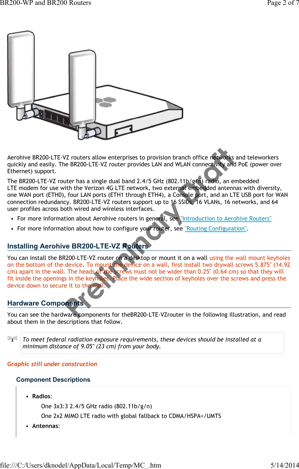
Aerohive BR200-LTE-VZ routers allow enterprises to provision branch office networks and teleworkers quickly and easily. The BR200-LTE-VZ router provides LAN and WLAN connectivity and PoE (power over Ethernet) support. The BR200-LTE-VZ router has a single dual band 2.4/5 GHz (802.11b/g/n) radio, an embedded LTEmodem for use with the Verizon 4G LTEnetwork, two external embedded antennas with diversity, one WAN port (ETH0), four LAN ports (ETH1 through ETH4), a Console port, and an LTE USB port for WAN connection redundancy. BR200-LTE-VZ routers support up to 16 SSIDs, 16 VLANs, 16 networks, and 64 user profiles across both wired and wireless interfaces. • For more information about Aerohive routers in general, see "Introduction to Aerohive Routers"• For more information about how to configure your router, see "Routing Configuration".Installing Aerohive BR200-LTE-VZ RoutersYou can install the BR200-LTE-VZ router on a desktop or mount it on a wall using the wall mount keyholes on the bottom of the device. To mount the device on a wall, first install two drywall screws 5.875" (14.92 cm) apart in the wall. The heads of the screws must not be wider than 0.25" (0.64 cm) so that they will fit inside the openings in the keyholes. Place the wide section of keyholes over the screws and press the device down to secure it to the wall.Hardware ComponentsYou can see the hardware components for theBR200-LTE-VZrouter in the following illustration, and read about them in the descriptions that follow.To meet federal radiation exposure requirements, these devices should be installed at a minimum distance of 9.05" (23 cm) from your body.Graphic still under constructionComponent Descriptions•Radios:One 3x3:3 2.4/5 GHz radio (802.11b/g/n)One 2x2 MIMO LTEradio with global fallback to CDMA/HSPA+/UMTS•Antennas:Page 2 of 7BR200-WP and BR200 Routers5/14/2014file:///C:/Users/dknodel/AppData/Local/Temp/MC_.htmPreliminary Draft
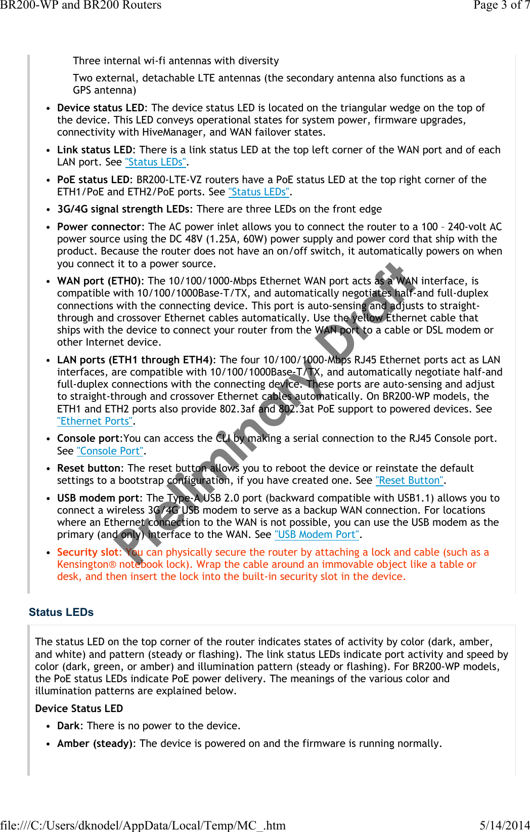
Three internal wi-fi antennas with diversityTwo external, detachable LTEantennas (the secondary antenna also functions as a GPSantenna)•Device status LED: The device status LED is located on the triangular wedge on the top of the device. This LED conveys operational states for system power, firmware upgrades, connectivity with HiveManager, and WAN failover states. •Link status LED: There is a link status LED at the top left corner of the WAN port and of each LAN port. See "Status LEDs".•PoE status LED: BR200-LTE-VZ routers have a PoE status LED at the top right corner of the ETH1/PoE and ETH2/PoE ports. See "Status LEDs".•3G/4G signal strength LEDs: There are three LEDs on the front edge•Power connector: The AC power inlet allows you to connect the router to a 100 – 240-volt AC power source using the DC 48V (1.25A, 60W) power supply and power cord that ship with the product. Because the router does not have an on/off switch, it automatically powers on when you connect it to a power source.•WANport (ETH0): The 10/100/1000-Mbps Ethernet WAN port acts as a WAN interface, is compatible with 10/100/1000Base-T/TX, and automatically negotiates half-and full-duplex connections with the connecting device. This port is auto-sensing and adjusts to straight-through and crossover Ethernet cables automatically. Use the yellow Ethernet cable that ships with the device to connect your router from the WAN port to a cable or DSL modem or other Internet device.•LANports (ETH1 through ETH4): The four 10/100/1000-Mbps RJ45 Ethernet ports act as LAN interfaces, are compatible with 10/100/1000Base-T/TX, and automatically negotiate half-and full-duplex connections with the connecting device. These ports are auto-sensing and adjust to straight-through and crossover Ethernet cables automatically. On BR200-WP models, the ETH1 and ETH2 ports also provide 802.3af and 802.3at PoE support to powered devices. See "EthernetPorts".•Console port:You can access the CLI by making a serial connection to the RJ45 Console port. See "Console Port".•Reset button: The reset button allows you to reboot the device or reinstate the default settings to a bootstrap configuration, if you have created one. See "Reset Button".•USBmodem port: The Type-A USB 2.0 port (backward compatible with USB1.1) allows you to connect a wireless 3G/4G USB modem to serve as a backup WAN connection. For locations where an Ethernet connection to the WAN is not possible, you can use the USB modem as the primary (and only) interface to the WAN. See "USBModem Port".•Security slot: You can physically secure the router by attaching a lock and cable (such as a Kensington® notebook lock). Wrap the cable around an immovable object like a table or desk, and then insert the lock into the built-in security slot in the device. Status LEDsThe status LED on the top corner of the router indicates states of activity by color (dark, amber, and white) and pattern (steady or flashing). The link status LEDs indicate port activity and speed by color (dark, green, or amber) and illumination pattern (steady or flashing). For BR200-WP models, the PoE status LEDs indicate PoE power delivery. The meanings of the various color and illumination patterns are explained below.Device Status LED•Dark: There is no power to the device.•Amber (steady): The device is powered on and the firmware is running normally.Page 3 of 7BR200-WP and BR200 Routers5/14/2014file:///C:/Users/dknodel/AppData/Local/Temp/MC_.htmPreliminary Draft
•Amber (flashing): The device is performing a firmware upgrade. Do not turn the device off while the LED is flashing.•White (steady): The device has made a CAPWAP connection to HiveManager and is operating properly.•White (flashing): The device is communicating with HiveManager either through a wireless connection or using a backup USB modem (if one is installed). Either the wired connection is not operating properly, or the port priority 1 has been changed from WAN/Eth0 to an alternate port. By default, the WAN/Eth0 port is given first priority (1). If you WAN port is configured for port priority 1, and you want are not seeing a successful wired connection to HiveManager, make sure that your Ethernet cable and modem are working properly, or contact your Internet service provider.Link Status LEDs•Dark: There is no link.•Green (steady): The Ethernet link is up but inactive at 1000 Mbps speeds.•Green (flashing): The Ethernet link is up and active at 1000 Mbps speeds.•Amber (steady): The Ethernet link is up but inactive at 10/100 Mbps speeds.•Amber (flashing: The Ethernet link is up and active at 10/100 Mbps speeds.PoE Status LEDs (BR200-WP)•Dark: No power is being provided through the port.•Green (steady): Port is delivering PoE normally to powered device.•Amber (steady): The port is experiencing a power overload.Ethernet PortsThere are four 10/100/1000-Mbps Ethernet RJ45 LAN ports (ETH 1 through ETH 4). These ports are compatible with 10/100/100Base-T/TX and automatically negotiate half- and full-duplex connections with the connecting device. These ports are auto-sensing and adjust to straight-through and crossover Ethernet cables automatically.To provide Ethernet connections to devices on the LAN side, connect the ETH 1 – ETH 4 interfaces on the router to a switch or host.On BR200 series routers, each of these ports represent a separate logical interface. For this reason, you can apply multiple LAN profiles (one for each of the four ports). In HiveManager, a LAN profile consists of a name, description, the ports to which it applies, and optional security and filtering rules. For information about how to configure a LAN profile, refer to HiveManager HelpThe pin assignments in the Ethernet ports follow the TIA/EIA-568-B standard. The ports accept standard Cat3, Cat5, or Cat6 Ethernet cable. Because the ports have autosensing capabilities, the wiring termination in the Ethernet cable can be either straight-through or crossover.For PoE ports, especially with 803.2at, Aerohive recommends using Cat5 or Cat6 Ethernet cable.PoE PortsOn BR200-WP routers, the ETH1/PoE and ETH2/PoE ports can provide to powered devices such as VoIP phones, wireless access points, and network cameras. These ports are IEEE802.3af and IEEE802.3at PSE (power sourcing equipment) compliant, as described here:• 802.3af PoE provides up to 12.95 W of DC power to each device (this rate reflects normal power loss through the cables). 802.3af meets the power demands of PoE Class 0, 1, 2, and 3 devices.Page 4 of 7BR200-WP and BR200 Routers5/14/2014file:///C:/Users/dknodel/AppData/Local/Temp/MC_.htmPreliminary Draft
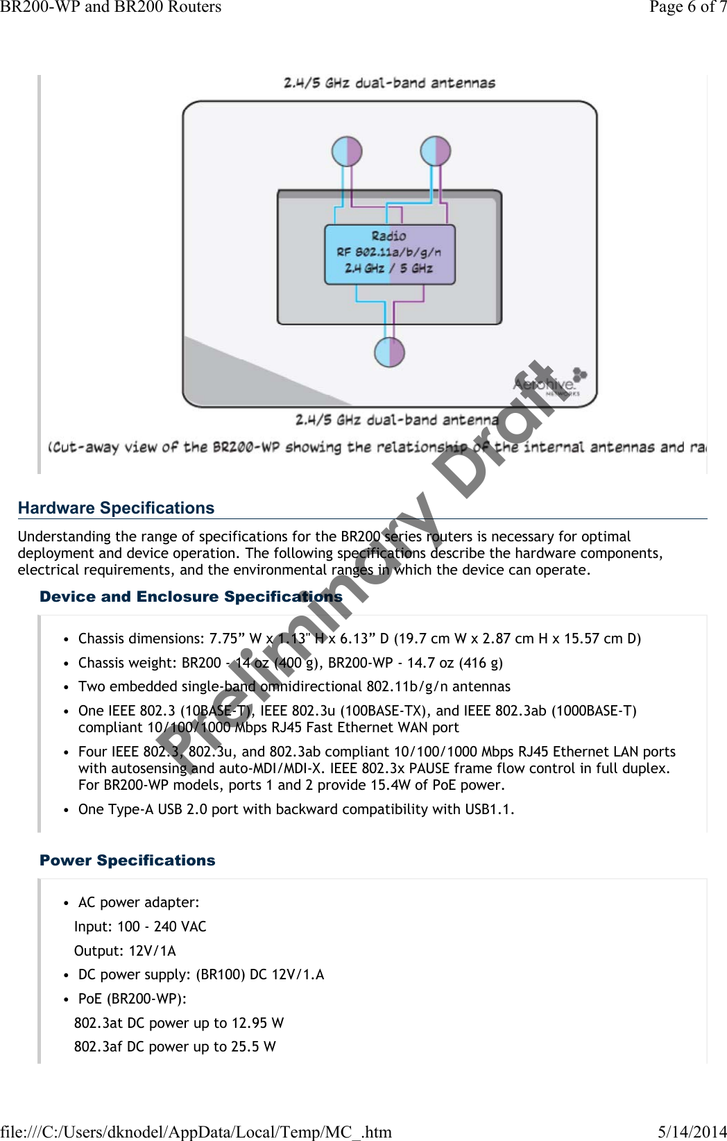
• 802.3at PoE provides up to 25.5 W of DC power to each device (this rate reflects normal power loss through the cables). 802.3at meets the power demands of PoE Class 4 devices.The BR200-WP router balances PoE power output automatically. For example, if a device connected to ETH1 requires more power than the port can provide, and if ETH1 has the higher priority, ETH2 shuts down and shifts all remaining power to ETH1. The router generates a log for every shutdown event.The BR200-WP router must be connected to an AC power source. It provides power to devices connected to one of its Eth1/PoE and Eth2/PoE LAN ports. Currently, problems can arise if the router is connected to a switch port that is enabled to provide PoE. When the router ports are plugged in to a PSE source, be sure to disable the PSE power source before plugging the cables into the router ports.Console PortUse the RJ45 Console port to make a serial connection between your management system and the router. The management station from which you connect to the device must have a VT100 emulation program, such as Tera Term Pro© (a free terminal emulator) or Hilgraeve Hyperterminal® (provided with Windows® operating systems from Windows 95 to Windows XP). The serial connection settings are: 9600 bits per second, 8 data bits, no parity, 1 stop bit, and no flow control. For Console port pin assignments, see "Aerohive Device Pin Assignments".Reset ButtonTo reset the device or restore factory setting, insert a paper clip or similar tool into the pinhole and press the Reset button. To reboot the device, hold the button down between 1 and 5 seconds. To return the configuration to the default settings, hold the button down for at least 5 seconds. When you release the button, the status LED goes dark as the system reboots, then turns amber while the firmware loads and the system performs a self-test. After the firmware has finished loading and the router has connected to HiveManager, the device status LED glows steady white.USB Modem PortRadios and AntennasBR200 routers have a single 3x3-stream 802.11a/b/g/n BR200-WP routers have a 3x3:3 dual-band 2.4/5 GHz radio that supports IEEE 802.11a/b/g/n and three embedded antennas with diversity. The figure below illustrates the relationship between the radio and antennas in a BR200-WP model. For a detailed description of the directional patterns for the antennas, see "Configuring Antennas".Page 5 of 7BR200-WP and BR200 Routers5/14/2014file:///C:/Users/dknodel/AppData/Local/Temp/MC_.htmPreliminary Draft
Hardware SpecificationsUnderstanding the range of specifications for the BR200 series routers is necessary for optimal deployment and device operation. The following specifications describe the hardware components, electrical requirements, and the environmental ranges in which the device can operate.Device and Enclosure Specifications• Chassis dimensions: 7.75” W x 1.13" H x 6.13” D (19.7 cm W x 2.87 cm H x 15.57 cm D)• Chassis weight: BR200 - 14 oz (400 g), BR200-WP - 14.7 oz (416 g)• Two embedded single-band omnidirectional 802.11b/g/n antennas• One IEEE 802.3 (10BASE-T), IEEE 802.3u (100BASE-TX), and IEEE 802.3ab (1000BASE-T) compliant 10/100/1000 Mbps RJ45 Fast Ethernet WAN port• Four IEEE 802.3, 802.3u, and 802.3ab compliant 10/100/1000 Mbps RJ45 Ethernet LAN ports with autosensing and auto-MDI/MDI-X. IEEE 802.3x PAUSE frame flow control in full duplex. For BR200-WP models, ports 1 and 2 provide 15.4W of PoE power.• One Type-A USB 2.0 port with backward compatibility with USB1.1.Power Specifications• AC power adapter:Input: 100 - 240 VACOutput: 12V/1A• DC power supply: (BR100) DC 12V/1.A• PoE (BR200-WP):802.3at DC power up to 12.95 W802.3af DC power up to 25.5 WPage 6 of 7BR200-WP and BR200 Routers5/14/2014file:///C:/Users/dknodel/AppData/Local/Temp/MC_.htmPreliminary Draft
Environmental Specifications• Operating temperature: 32°F to 104°F (-0 to 40°C)• Storage temperature: -4°F to 158°F (-20 to 70°C)• Operating humidity: 10% to 90% (noncondensing)• Storage humidity: 5% to 95% (noncondensing)• RoHS compliantMini-TOC Level 1Mini-TOC Level 2Mini-TOC Level 3Mini-TOC Level 4Mini-TOC Level 5Mini-TOC Level 6Mini-TOC Level 7Mini-TOC Level 8Mini-TOC Level 96.1r5 New Features Guide | 6.1r5 Release Notes | www.aerohive.com | Aerohive BlogsClick or Scan QRcode below for the dedicated Mobile Help system:Copyright © 2014Aerohive Networks, Inc. Page 7 of 7BR200-WP and BR200 Routers5/14/2014file:///C:/Users/dknodel/AppData/Local/Temp/MC_.htmPreliminary Draft

Navigation menu