Aerohive Networks HIVEAP170 Wireless Access Points User Manual HiveAP 170 Installation Guide
Aerohive Networks, Inc. Wireless Access Points HiveAP 170 Installation Guide
Contents
- 1. User Man (Operation)_WBV-HIVEAP170
- 2. User Man (Statement)_WBV-HIVEAP170_rev. 1
- 3. Updated user manual-compliance sheet
User Man (Operation)_WBV-HIVEAP170
P/N 330052-01, Rev. A 1
HIVEAP 170
INSTALLATION GUIDE
This guide explains how to mount a HiveAP 170 to a pole or flat surface in virtually any outdoor
setting, and connect it to HiveManager over the network. To register, get product documentation, see
compliance information, and download software updates, visit www.aerohive.com/support.
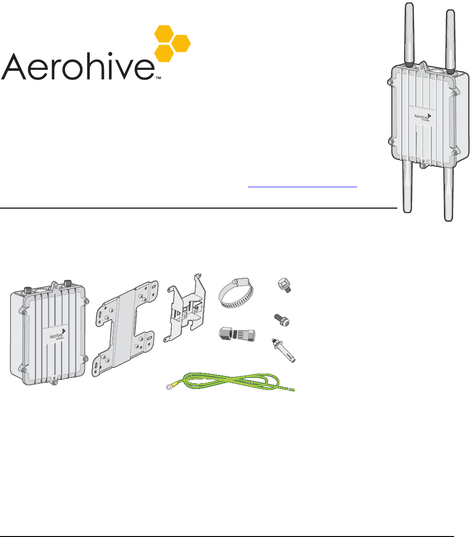
KIT CONTENTS, REQUIRED ACCESSORIES, AND TOOLS
The HiveAP 170 kit includes the items shown in Figure 1.
Figure 1 HiveAP 170 kit contents
To install your HiveAP 170, you will need the following accessories (ordered separately) and tools:
• (2) 2.4 GHz antennas (AH-ACC-170-ANT-2G)
• (2) 5 GHz antennas (AH-ACC-170-ANT-5G)
• A switch that provides PoE power, or a PoE provisioning device
• (1) shielded cat5 Ethernet cable rated for outdoor use; length not to exceed 328 feet (100 m)
• Crosshead screwdriver for 1/4” (6 mm) x 3/8” (10 mm) screws
• Drive sockets (nut drivers) for 3/8” (10 mm) nuts
• Flat blade screwdriver to tighten hose clamp
SAFETY INSTRUCTIONS AND SITE HAZARD WARNINGS
Read and follow these safety instructions and hazard warnings before installing a HiveAP 170 outdoors. Keep these
instructions for future reference.
• To comply with RF (radio frequency) exposure limits, do not place the HiveAP 170 within 8" (20 cm) of people.
• You can install the HiveAP 170 in wet, windy locations. Therefore, make sure to install the Ethernet cable
housing for a complete waterproof connection.
• To protect the HiveAP 170 from lightning, do not place it at the highest point of a building or structure.
Plane Bracket (1)
HiveAP 170
Base
Bracket (1)
(4) Sleeve-Bolt Assembly
Sleeve, 5/8” (16 mm),
Bolt 1 15/16” (5 cm),
Hex nut 3/8” (10 mm),
Washer 5/8” (16 mm)
(4) Round Head Screw 1/4” (6 mm)
Lock Washer, Flat Washer
(4) Hex Head Bolt, 3/8”x1/2”
(10 mm x 13 mm)
Lock Washer, Flat Washer 1/2” (13 mm)
Hose Strap (1)
Ground Cable (1)
Ethernet
Housing (1)

Aerohive Networks
2
DEVICE, POWER, AND ENVIRONMENTAL SPECIFICATIONS
Understanding the range of specifications for the HiveAP 170 is necessary for optimal deployment and device
operation. The following specifications describe the hardware components, PoE (Power over Ethernet) electrical
requirements, and the environmental ranges in which the device can operate.
Device and Enclosure Specifications
• HiveAP dimensions (without antennas): 9 5/8” long x 7 7/8” wide x 3" high (22.4 cm x 20 cm x 7.6 cm)
• HiveAP weight: 4.85 lb. (2.199 kg) with antennas, 6.05 lb (2.744 kg) with antennas and brackets
• Antennas: 4 N-type female connectors for external antennas
• Ethernet connector: autosensing 10/100/1000 Base-T Mbps; compliant with the IEEE 802.3at standard for PoE
• Mounting options:
• Horizontal or vertical pole mount; pole must be 1" to 3.5" (2.5 cm to 8.9 cm) in diameter
• Wall or flat surface mount
Power Specifications
• PoE nominal input voltages: 48 V, 30 watts
Environmental Specifications
• Operating temperature: -40 to 131 degrees F (-40 to 55 degrees C)
• Storage temperature: -40 to 176 degrees F (-40 to 80 degrees C)
• Relative humidity: Maximum 100%
• Wind survivability: > 165 mph (266 kph)
• Environmental compliance: IP68
Make sure that the HiveAP 170 is connected to a suitably installed ground conductor. Contact the
appropriate electrical inspection authority if you are uncertain that suitable grounding is available.
Do not locate the HiveAP 170 enclosure near overhead power lines or other electric light or power circuits,
or where it can come into contact with such circuits. During installation, exercise extreme care not to
come into contact with these circuits, which can cause serious injury or death. For proper installation and
grounding of the product, refer to national and local electrical codes: NFPA (National Fire Protection
Association) 70, National Electrical Code Article 810 (U.S.); Canadian Electrical Code, Part I, CSA 22.1 and
Section 54 (Canada); and if local or national electrical codes are not available, refer to IEC (International
Electrotechnical Commission) 364, Part 1 through 7 (other countries).
Do not connect or disconnect antennas or cables from the HiveAP 170 during periods of lightning activity.
To install the HiveAP 170, you must be a qualified installation professional, licensed or certified in
accordance with local regulations.
Use only attachments and accessories specified by Aerohive.
During operation, the surfaces of the HiveAP 170 can become hot. Use caution when handling it.
3
Aerohive Networks
MOUNTING THE HIVEAP 170
You can mount the HiveAP 170 on a variety of outdoor structures and adjust the orientation to vertical for optimum
radio transmission. For example, you can mount the HiveAP 170 on a non-penetrating roof stand or to a Winegard
bracket, often used for mounting satellite dishes. The mounting bracket is adjustable to fit poles with a 1" to 3.5"
(2.5 cm to 8.9 cm) diameter.
To provide unobstructed RF coverage, mount the HiveAP 170 in a relatively open area. At a minimum, mount it on a
pole, mast, of flat surface so that the antennas have at least a three-foot clearance from any nearby obstructions.
After checking that you have all the materials and tools necessary, and familiarizing yourself with the safety and
site hazard warnings, you are ready to mount the unit. You can mount the HiveAP 170 on a vertical or horizontal
pole, or attach it to a flat surface. These options are described below. The device and mounting accessories
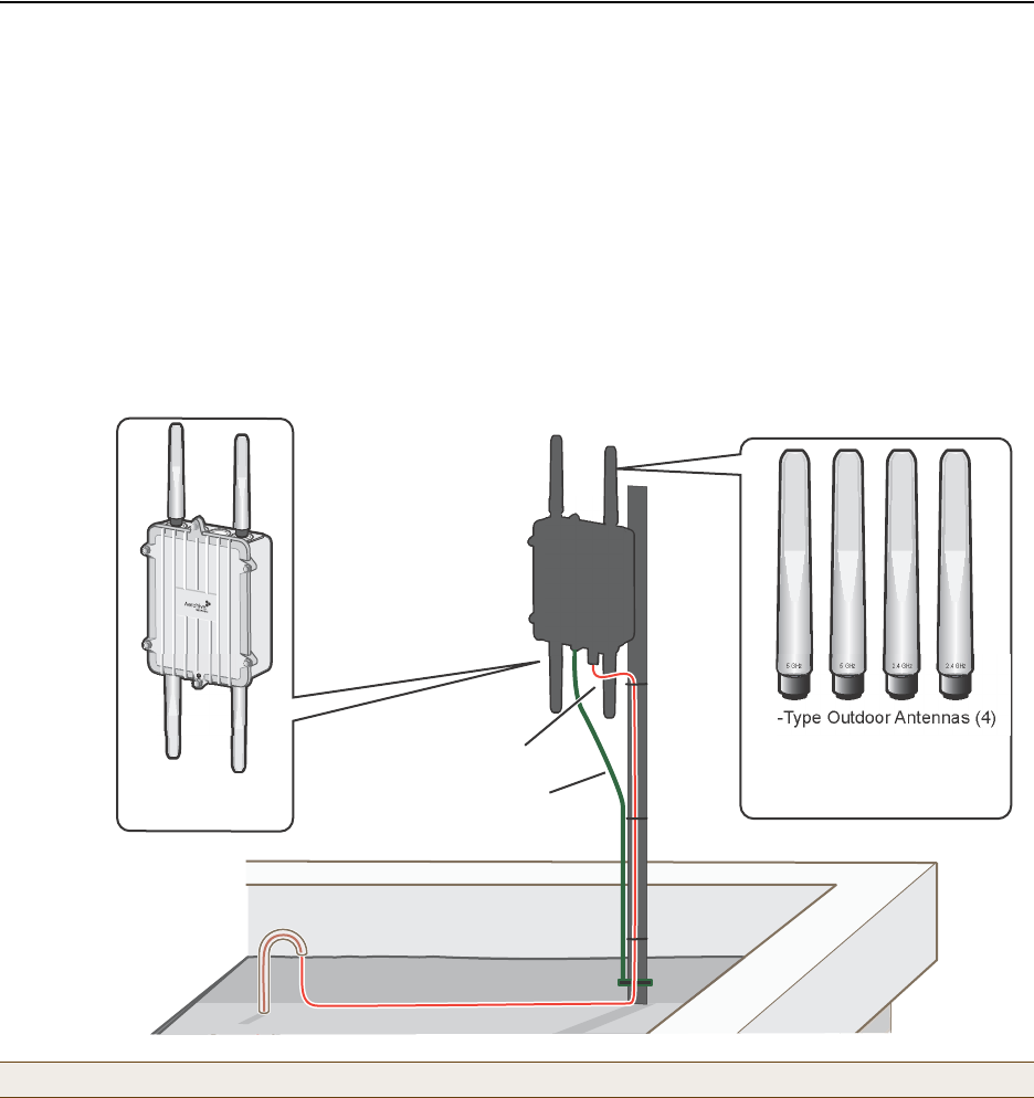
required for mounting the HiveAP 170 are shown in Figure 2.
Figure 2 HiveAP 170 mounted on a vertical pole with major devices and accessories called out
PoE Connections
In most cases, you can connect an Ethernet cable directly from your HiveAP 170 to a PoE-enabled switch, or to a PoE
injector inside the building (see Figure 2). If you are not using a PoE-enabled switch, you must connect to an
intermediary PoE injector, then to your switch (see Figure 4 on page 8). In cases where your HiveAP 170 is located a
significant distance from the building, you can install an outdoor waterproof PoE injector, available separately (SKU
AH-ACC-OINJ-30W).
Note: For best performance, deploy HiveAPs at least 100 feet (30.5 m) apart from each other.
The HiveAP 170 mounted
on a grounded vertical pole.
A shielded Ethernet cable
provides both the network
connection and power
through PoE.
The HiveAP 170 ground
wire is connected to
the grounded pole.
HiveAP 170
(AH-AP-170-N-XX)
Shielded Ethernet Cable
N-Type Outdoor Antennas (4)
AH-ACC-170-ANT-KIT
AH-ACC-170-ANT-2G (2)
AH-ACC-170-ANT-5G (2)
5 GHz 2.4 GHz
Ground wire connected
to grounded pole
5 GHz
2.4 GHz
Aerohive Networks
4
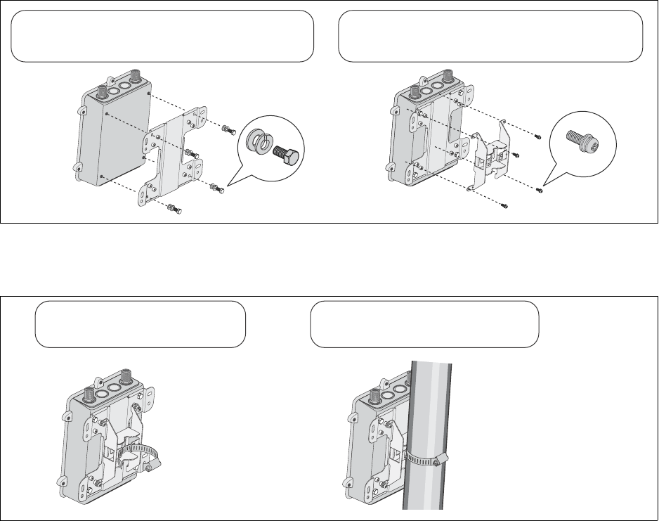
Vertical Pole Mount
The following steps explain how to mount the HiveAP 170 on a vertical pole.
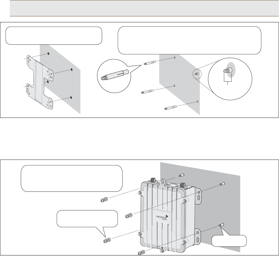
1. Attach the plane bracket to the back of the unit using the hex bolts, lock washers and flat washers. Tighten the
bolts with a socket or nut driver.
2. Mount the base bracket to the plane bracket using the round-head screws, lock washers, and flat washers.
Tighten the screws with a crosshead screwdriver.
3. Thread the open end of the hose strap through the two tabs on the base bracket.
4. Fit the hose strap around the pole and tighten the clamp with a 1/4” (2 cm) slotted screwdriver or a 5/16” (8
mm) drive socket (or nut) driver.
5. Connect the grounding cable to the grounding lug on the unit, as shown in Figure 3 on page 7. Connect the other
end of the cable to an appropriate ground.
Attach the plane bracket to the back of the unit using
(4) 3/8” x 1/2” (10 mm x 13 mm) hex head bolts and
1/2” (13 mm) lock washers and flat washers.
Attach the base bracket to the plane bracket using
(4) 1/4” (6 mm) round head screws with lock washers
and flat washers.
Plane Bracket Base Bracket
12
Hose Strap
Thread the hose strap through the
two tabs on the base bracket.
Use a flat blade screwdriver to tighten
the hose strap around the pole.
34
5
Aerohive Networks
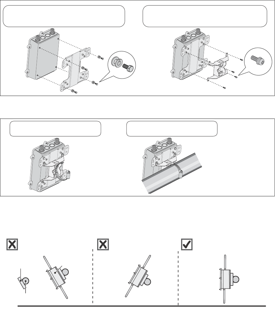
Horizontal Pole Mount
The following steps explain how to mount the HiveAP 170 on a horizontal pole.
1. To mount the HiveAP 170 on a horizontal pole, first attach the plane bracket to the back of the unit using the
four hex-head bolts with lock washers and flat washers.
2. Mount the base bracket to the plane bracket using the four round-head screws, so that is oriented horizontally.
Each screw should have a lock washer and flat washer.
3. Thread the open end of the hose strap through the two tabs on the base bracket.
4. Tighten the hose clamp with a 1/4” (2 cm) slotted screwdriver or a 5/16” (8 mm) drive socket (or nut) driver.
5. Connect the grounding cable to the grounding lug on the unit, as shown in Figure 3 on page 7. Connect the other
end of the cable to an appropriate ground.
When attaching the HiveAP 170 to a horizontal pole, such as the arm of a street light, make sure that the face of the
device is perpendicular to the Earth for optimal RF coverage.
Attach the plane bracket to the back of the unit using
(4) 3/8” x 1/2” (10 mm x 13 mm) hex head bolts and
1/2” (13 mm) lock washers and flat washers.
Attach the base bracket to the plane bracket using
(4) 1/4” (6 mm) round head screws with lock washers
and flat washers.
Plane Bracket
Base Bracket
12
Hose Strap
Thread the hose strap through the two
tabs on the base bracket.
Use a flat blade screwdriver to tighten
the hose strap around the pole.
34
Earth
Horizontal Pole
Pole Bracket
HiveAP 170
Device
Not good. Angled slant of unit and
antennas provides suboptimal
RFcoverage.
Not good. Angled slant of unit
and antennas provides subopti-
mal RF coverage.
Good! Unit is perpendicular to Earth
and antennas are oriented vertically
for optimal RF coverage.
Aerohive Networks
6
Flat Surface Mount
The following steps explain how to mount the HiveAP 170 on a flat surface. You will need the plane bracket and the
four sleeve-bolt assemblies.
1. Use the plane bracket as a template to mark the location of the mounting holes on the surface.
2. Drill a 5/16” (8 mm) hole to a depth of 1.5" (38 mm) into each mark.
3. Remove the nuts and washers and hammer the unthreaded end of a sleeve-bolt assembly into each hole. Make
sure the slotted end of the sleeve goes into the wall. Be sure to leave a minimum of 3/8” (9.5 mm) of the
threaded bolt protruding from the front of the wall.
4. Place a lock washer and flat washer on each of the four hex screws and use the screws to attach the plane
bracket to the back of the HiveAP 170, as shown in Step 1 on page 4.
5. Place the holes in the plane bracket over the mounting bolts and attach the unit using a hex nut, lock washer,
and flat washer on each bolt to tighten the unit to the surface. As you tighten the nuts, the flanges on the back
of the bolt sleeve will expand in the hole, securing the device in place.
6. Connect the grounding cable to the grounding lug on the unit, as shown in Figure 3 on page 7. Connect the other
end of the cable to an appropriate ground.
Note: If you are not installing the device on a concrete wall, you can use 2" (5 cm) threaded screws and plastic
wall anchors (not supplied) to mount the device.
Plane Bracket
Use base bracket as a template to mark
mounting holes on the flat surface.
Drill a 5/16” (8 mm) hole to a depth of 1.5” (38 mm) in each
mark. Remove nuts and washers and hammer the
unthreaded end of an assembly into each hole. Leave at
least 3/8” (9.5 mm) of the bolt protruding from the surface.
3/8” (9.5 mm)
2, 3
1
Bolt-Sleeve
Assembly
Hex nut with lock washer
and flat washer
Mounting Bolt
Place the holes in the plane bracket over
the mounting bolts. Tighten the unit to the
wall using a hex nut, lock washer, and flat
washer on each bolt.
5
7
Aerohive Networks
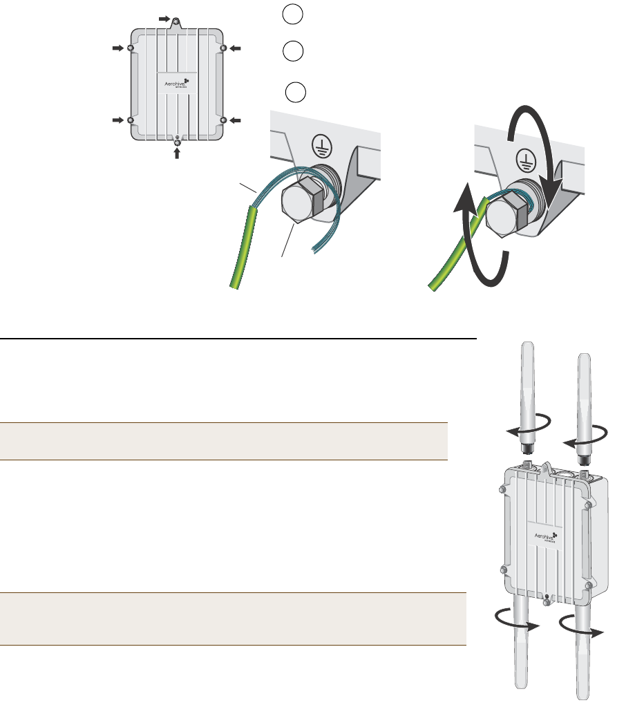
Figure 3 Connecting the grounding cable to the grounding lug on the unit
ATTACHING EXTERNAL ANTENNAS
Once you have grounded your HiveAP 170, you are ready to connect the antennas.
The omnidirectional antennas are available from Aerohive (SKUs AH-ACC-170-ANT-2G,
AH-ACC-170-ANT-5G). These antennas fit the N-type antenna connectors on the top
and bottom of the HiveAP 170. The two connectors on the bottom of the unit are for
the 2.4 GHz antennas, and the two on the top of the unit are for the 5 GHz antennas
(device and antennas are labeled).
To connect the antennas, screw them onto the antenna connectors by hand, turning
them clockwise until tight.
Note: It is extremely important to properly ground your device to complete
your installation.
Note: You do not need to use a tool to tighten the antennas or apply self-
amalgamating PTFE (polytetrafluoroethylene) tape around the threads of
the connectors to create a waterproof seal.
Remove the short piece of cable sheath from the end of
the grounding cable that does not have the connector.
Wrap the exposed wires clockwise snugly around one
of the six grounding lugs and tighten the nut securely.
Connect the other end of the grounding cable to a
proper ground.
Exposed wire
Grounding nut
Grounding lugs
1
2
3
5 GHz
5 GHz
2.4 GHz
2.4 GHz
Aerohive Networks
8
ATTACHING THE ETHERNET CABLE WATERPROOF HOUSING
The following steps explain how to ensure a weatherproof seal for the Ethernet cable using the waterproof housing.
1. Disassemble the waterproof housing.
There are three pieces: a threaded nut, a slotted cable grip, and a threaded housing.
2. Slide the threaded nut over the Ethernet cable.
3. Slip the slotted cable grip onto the Ethernet cable in front of the threaded nut.
4. Slide the threaded housing onto the cable and over the cable grip (the grip fits inside the housing).
5. Screw the threaded nut onto the threaded housing.
6. Plug the Ethernet cable into the connector. Screw the assembled housing onto the threaded connector cover.
7. Connect the other end of the Ethernet cable to a PoE-enabled switch, or PoE injector. See Figure 4 on page 8.
CONNECTING TO THE NETWORK
The final step to the installation is to connect the HiveAP 170 to the network so that it can form a CAPWAP
connection to HiveManager, as shown in Figure 4.
After you cable the HiveAP to an Ethernet network and it is receiving PoE power, it automatically attempts to get its
network settings through DHCP and contact HiveManager. The process typically takes about five minutes to
complete. If you see the HiveAP listed on the Monitor > Access Points > HiveAPs page in the HiveManager GUI, the
initial setup is complete and you can begin managing the HiveAP through HiveManager.
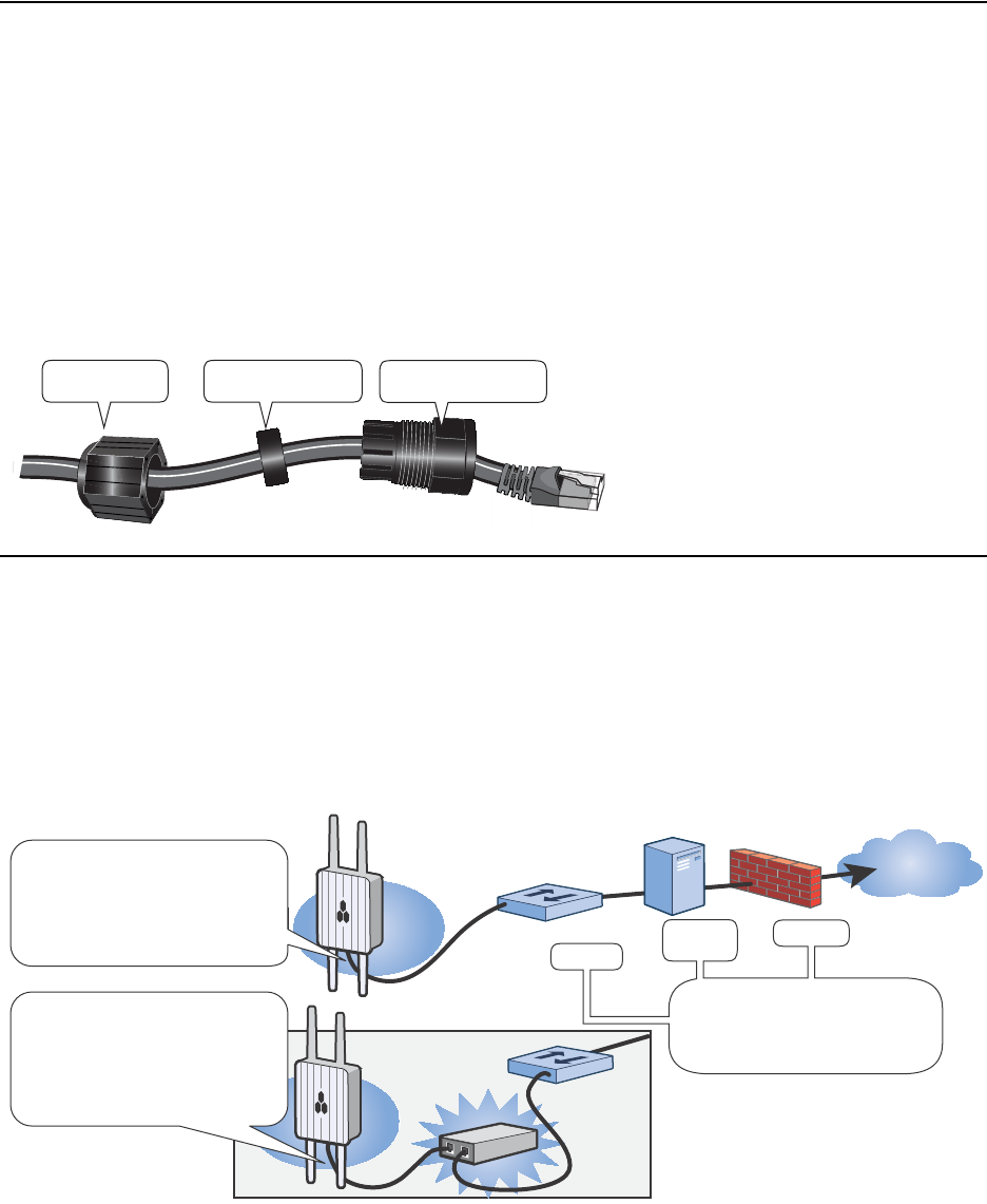
Figure 4 Connecting the HiveAP 170 to the network
If the HiveAP does not appear in the HiveManager GUI after about ten minutes, read the rest of this guide to
understand how the HiveAP attempts to contact HiveManager and what you can do to help establish a connection
between the two devices.
Slotted Cable Grip Threaded Housing
Threaded Nut
Internet
Switch
Firewall
Some other network devices
(they might all be incorporated
in the same device, such as a
router or firewall).
DHCP
Server
Ethernet Cable
HiveAP 170
PoE Injector
Switch
If the switch provides PoE,
connect a standard Ethernet
cable from the HiveAP directly to
the switch. The HiveAP will
power on in a few seconds.
If the switch does not provide
PoE, first connect a standard
Ethernet cable from the HiveAP
170 to a PoE provisioning device,
then connect the provisioning
device to the switch.
9
Aerohive Networks
Connecting to HiveManager
By default, a HiveAP acts as a DHCP client, and gets its network settings automatically from a DHCP server. (You can
also configure it with static network settings through the CLI. See "Using the Virtual Access Console" on page 10.)
After a HiveAP has its network settings, it then acts as a CAPWAP client and sends CAPWAP Discovery messages until
HiveManager, acting as the CAPWAP server, responds. CAPWAP (Control and Provisioning of Wireless Access Points) is
a protocol that access points use to contact and communicate with a management device and
When a HiveAP goes online for the first time without any specific CAPWAP server configuration entered manually or
received as a DHCP option, it progresses through the cycle of CAPWAP connection attempts shown in Figure 5.
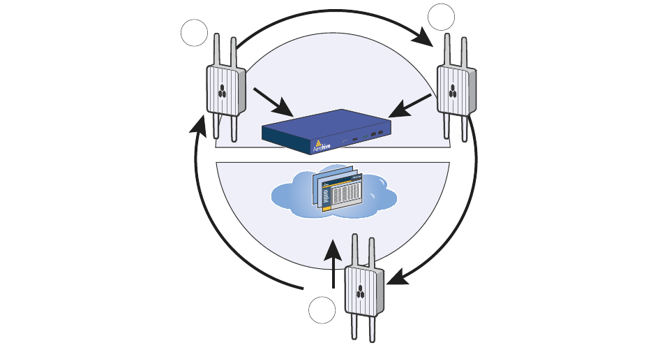
Figure 5 Connecting to HiveManager
If a HiveAP forms a CAPWAP connection with the redirection server and its serial number of MAC address has been
assigned to a previously created VHM, to a physical HiveManager appliance, or to a HiveManager Virtual Appliance,
the redirection server automatically redirects the CAPWAP connection to that HiveManager instance. The
redirection server does this by sending the HiveAP the HiveManager domain name or IP address as its new CAPWAP
server. If the HiveAP is currently using HTTP and it will be redirected to a HiveManager Online VHM, the redirection
server also sends it the configuration needed to continue using HTTP. Similarly, if the HiveAP is accessing the
network through an HTTP proxy server, the redirection server also saves those settings on the HiveAP so it can reach
the HiveManager Online VHM using HTTP through the HTTP proxy server.
If the redirection server must redirect the HiveAP to a standalone HiveManager appliance or HiveManager Virtual
Appliance, then you must configure the connection settings on the redirection server that you want it to push to the
HiveAP to make that connection. The HiveAP first uses whatever settings are configured on it to reach the
redirection server, which might be on the other side of an HTTP proxy server or firewall that only permits outbound
HTTP traffic. Then the redirection server might supply the HiveAP with different settings so that the HiveAP can
reach a standalone HiveManager instance, which might be on the same side of the HTTP proxy server or firewall as
the HiveAP and therefore requires different connection parameters.
If the HiveAP serial number or MAC address is in the redirection server but the VHM has not yet been created or the
connection settings of the standalone HiveManager have not yet been configured on the redirection server, then the
HiveAP remains in the redirection server. The HiveManager admin must manually reassign it later to the appropriate
HiveManager.
(b) If the DNS server cannot resolve
the domain name to an IP address,
the HiveAP broadcasts CAPWAP
Discovery messages on its
local subnet. If HiveManager
is on the local network and
responds, they form a
secure CAPWAP connection.
(c) If the first two searches for a
local HiveManager produce no
results, the HiveAP tries to
contact HiveManager Online at
redirector.aerohive.com:12222.
If the Aerohive redirection server
has a serial number for that HiveAP
in its ACL, it responds and they form
a secure CAPWAP connection. If the
HiveAP cannot make a CAPWAP
connection to HiveManager Online on UDP
port 12222, it tries to reach it on TCP port
80. If this is unsuccessful, the HiveAP
returns to the initial search through a DNS
lookup and repeats the cycle.
(a) The HiveAP tries to connect to
HiveManager using the default
domain name
“hivemanager.<local_domain>”,
where “<local_domain>” is the
domain name that a DHCP server
supplied to the HiveAP and 12222 is
the UDP port number. If a DNS
server has been configured to
resolve that domain name to an IP
address, the HiveAP and
HiveManager then form a secure
CAPWAP connection on port 12222.
If the HiveAP cannot make a
CAPWAP connection to
HiveManager on port 12222, it tries
to reach it by using TCP port 80:
hivemanager.<local_domain>:80.
HiveManager
or
HiveManager Virtual
Appliance
HiveManager Online
c
ab
Aerohive Networks
10
Using the Virtual Access Console
A HiveAP connected directly to the network is called a portal. You can also place a HiveAP within radio range of a
portal so that it forms a wireless link through the portal to the wired network. If the HiveAP forms a CAPWAP
connection with the Aerohive redirection server and its serial number has been entered in an ACL, the redirection
server automatically redirects the CAPWAP connection the corresponding HiveManager Online VHM (virtual
HiveManager). The redirection server sends the HiveAP the HiveManager domain name of IP address as its new
CAPWAP server and the name of the appropriate VHM. If the HiveAP is currently using HTTP, the redirection server
includes the configuration needed for the HiveAP to continue using it. Similarly, if the HiveAP is configured to access
the public network through an HTTP proxy server, the redirection server saves the relevant settings on the HiveAP so
it will continue using the HTTP proxy server when connecting to HiveManager.
If the redirection server does not have the HiveAP serial number, the ACL ignores the CAPWAP connection attempts,
and the HiveAP repeats the connection cycle shown in Figure 6.
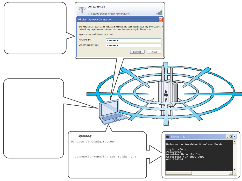
Figure 6 Accessing the virtual console
C:\>
Ethernet adapter Wireless
Network Connection:
IP Address. . . . . . : 1.1.1.2
Subnet Mask . . . . . : 255.255.255.0
Default Gateway . . . : 1.1.1.1
C:\>telnet 1.1.1.1
Using your wireless client,
scan for wireless networks.
If you are within range, an
SSID such as
“AH-123456_ac” appears.
Select the SSID, and when
prompted to enter a network
key, type aerohive, and then
click Connect.
Wireless Client
Beacons
Beacons
Check the IP address of
the default gateway that
the DHCP server on the
HiveAP assigned to your
client. Then make an SSH
or Telnet connection to the
HiveAP at that IP address.
(Note that the Telnet
connection is protected by
WPA2 security mecha-
nisms.) When prompted to
enter your credentials,
enter the default Aerohive
login name (admin) and
password (aerohive)

11
Aerohive Networks
After logging in to the virtual access console, you can view the status of various functions and make configuration
changes. Here are some commonly used commands.
To see a list of commands, and their accompanying CLI Help, type a question mark ( ? ). For example, to see all
of the show commands, enter show ?
If you want to find a command that uses a particular character or string of characters, you can do a search using
the following command: show cmds | include <string>, where <string> is the word or string of
characters you want to find.
Device- and platform-specific CLI reference guides are available online. (To learn how to access them, see
“Where to go for More Information” at the end of this document.)
DEPLOYMENT AND CONFIGURATION TIPS
This section contains tips and suggestions to help you troubleshoot any problems you may experience when you set
up your HiveAP.
• If the client fails to authenticate to an SSID using a PSK (preshared key), check that the PSK on the client
matches that on the HiveAP and reset one or both keys if necessary.
• If you manage the HiveAP through HiveManager Online and it does not show up on the Monitor > Access Points
> HiveAPs page, do the following:
• Check if the HiveAP serial number is listed in the ACL on the Aerohive redirection server. Log in to
myaerohive.com, and then click Redirector > Monitor > HiveAP Access Control List. If the serial number is
not in the ACL, click Enter, type the serial number in the HiveAP Serial Number field, and then click Save.
When done, reboot the HiveAP.
Use these commands: To do the following:
show interface Check the status of both wired and wireless interfaces
show interface mgt0 See the network settings (IP address, netmask, default
gateway) and VLAN ID of the mgt0 interface, which is the
management interface of the HiveAP.
no interface mgt0 dhcp client Disable the DHCP client
interface mgt0 ip <ip_addr> <netmask> Set the IP address and netmask of the mgt0 interface
interface mgt0 native-vlan <id> Set the native (untagged) VLAN that the switch
infrastructure in the surrounding wired and wireless
network uses
show capwap client See CAPWAP client settings and status
show hive See the hive name
show hive <string> neighbor Check for any neighboring hive members
hive <string>... Create a hive and set its parameters
show ssid See a list of all SSID names
ssid <string>... Configure an SSID
interface { wifi0 | wifi1 } ssid
<string>
Bind an SSID to a wireless interface in access mode
save config Save the configuration to flash
reboot Reboot the HiveAP
Set the following command only when managing HiveAPs through HiveManager or HiveManager Virtual
Appliance. Do not use this command with HiveManager Online.
capwap client server name <string> Set the IP address or domain name of the CAPWAP server
(HiveManager)

Aerohive Networks
12
• Check connectivity to HiveManager Online:
ping redirector.aerohive.com
capwap ping redirector.aerohive.com
• Ensure that any intervening firewalls allow one of the following sets of services from the HiveAP to
HiveManager Online:
CAPWAP (UDP 12222), SSH (TCP 22), and HTTPS (TCP 443)
or
HTTP (TCP 80) and HTTPS (TCP 443)
• If a wireless client cannot form an association with an SSID, check that it is within range and is configured to use
the same authentication method as the SSID. For example, if the client is configured to use Open or WEP
authentication but the SSID is set for WPA or WPA2, the client will not be able to associate with the HiveAP. To
see the security settings for an SSID, click Configuration > SSIDs > ssid_name > Advanced Access Security
Settings, and look at the SSID access security type, the key management method, and the encryption method.
• If the client associates and authenticates itself, but the HiveAP cannot forward traffic, check that the HiveAP is
assigning the correct user profile, and if so, that it is also assigning the correct VLAN. To see the user profile and
VLAN that a HiveAP assigns to a client, log in to HiveManager, click Monitor > Clients > Active Clients >
client_mac_address. Check the user profile attribute and VLAN. If they are correct, then check that the client
has received its network settings through DHCP. To check connectivity to a DHCP server, click Tools > VLAN
Probe, choose the HiveAP with which the client is associated from the HiveAP drop-down list, and enter IDs for
the VLAN range that you want to check. Click Start to send a DHCP DISCOVER message, and see if it elicits a
response. Also check that the VLAN configuration for the port on the connecting switch is correct.
To remove all settings and return the configuration to its factory default settings, enter the reset config
command or use a pin to press the Reset button on the chassis and hold it down for at least 10 seconds.
WHERE TO GO FOR MORE INFORMATION
Technical Documentation
Aerohive provides various technical documents for its products. For information about CLI commands, see the
CLI reference guides available in HTML format. For information about HiveManager and HiveAP hardware and
software topics, see the Aerohive Deployment Guide (PDF). The deployment guide contains information about
HiveAPS and HiveManager appliances, WLAN deployment considerations, and detailed configuration instructions
for commonly used features. To access Aerohive product documentation, visit www.aerohive.com/techdocs.
HiveManager Help System
The HiveManager Help system contains a wealth of information about all the features you can configure through
HiveManager. To access it, click the Help icon in the upper right corner of the GUI. A Help topic that pertains to
the currently active GUI page appears. To see other Help topics, use the table of contents to browse the system
or the search tool to find information about a specific subject.
Support Site
Access technical support services, documentation, and software at www.aerohive.com/support/login.html.
After registering for an account, you will receive a user name and password to enter when logging in. You can
contact Support for assistance through the web site or by phone (+1 408.510.6100 or 866.365.9918).
Training
Aerohive offers courses covering the Aerohive cooperative control concepts, the installation and configuration
of Aerohive products, and how to troubleshoot issues and optimize performance. For more information, visit
www.aerohive.com/support/training.html.
Aerohive also offers CBT (computer-based training) modules. CBTs are online Flash tutorials that explain
Aerohive concepts and walk you through configuration procedures step by step. You can use CBTs to familiarize
yourself with the HiveManager GUI and learn how to configure HiveAPs. Aerohive CBTs are available for free
online at www.aerohive.com/techdocs.