Afimilkricultural Cooperative 4256000 Wireless reader User Manual
SAE Afikim Wireless reader
UserManual.wiki
>
Afimilkricultural Cooperative
>
4256000 User Manual
>
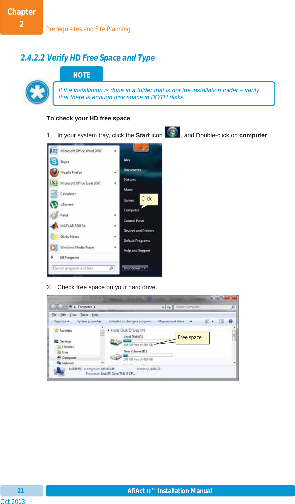
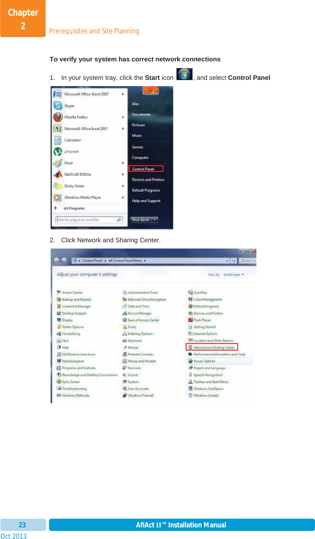
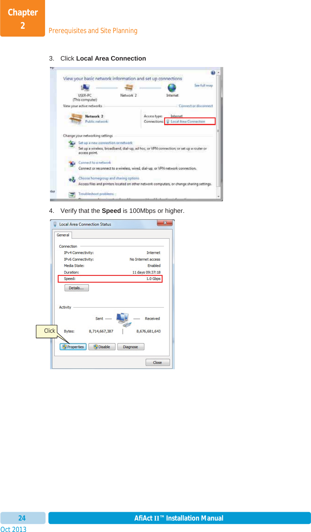
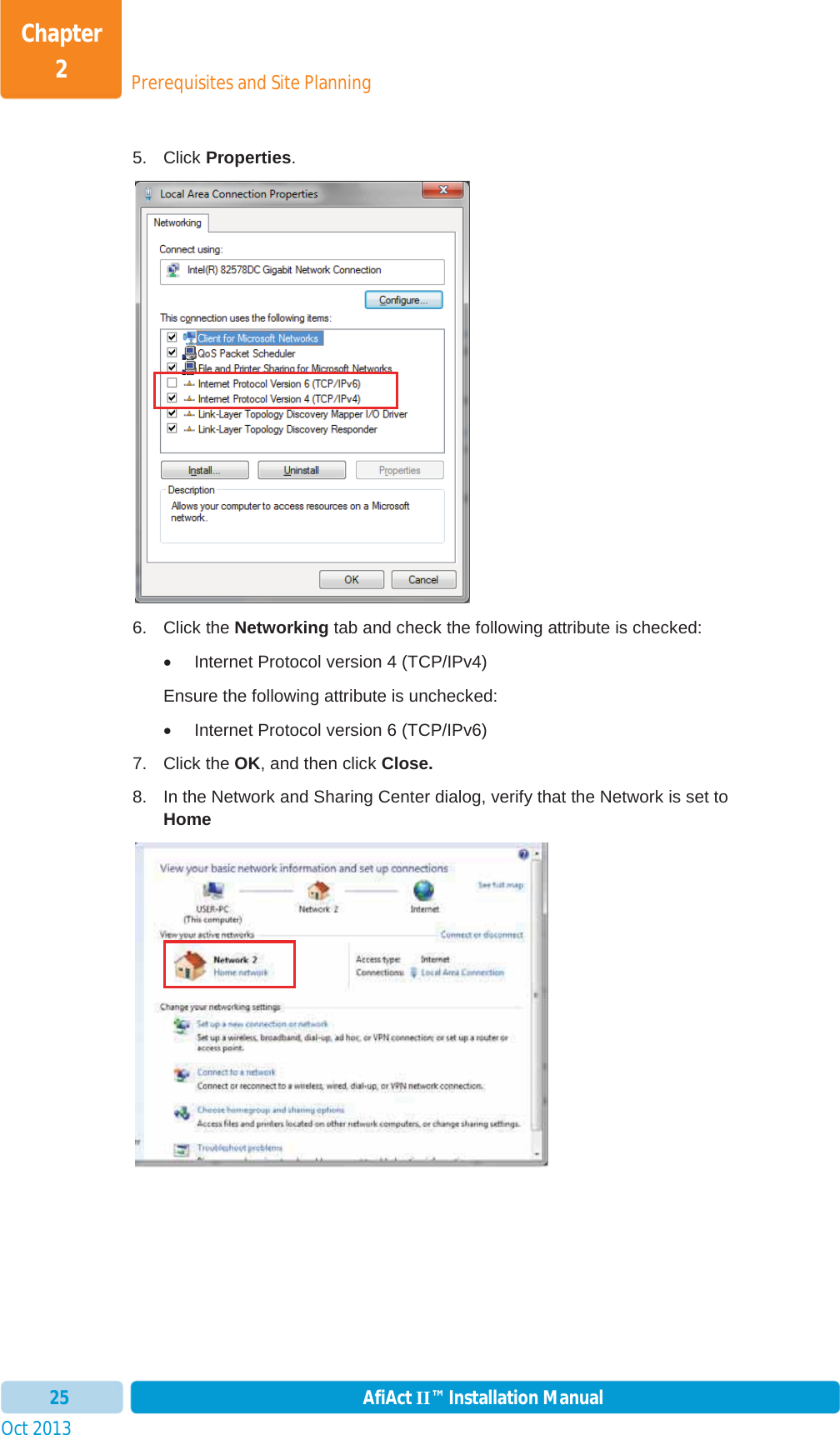
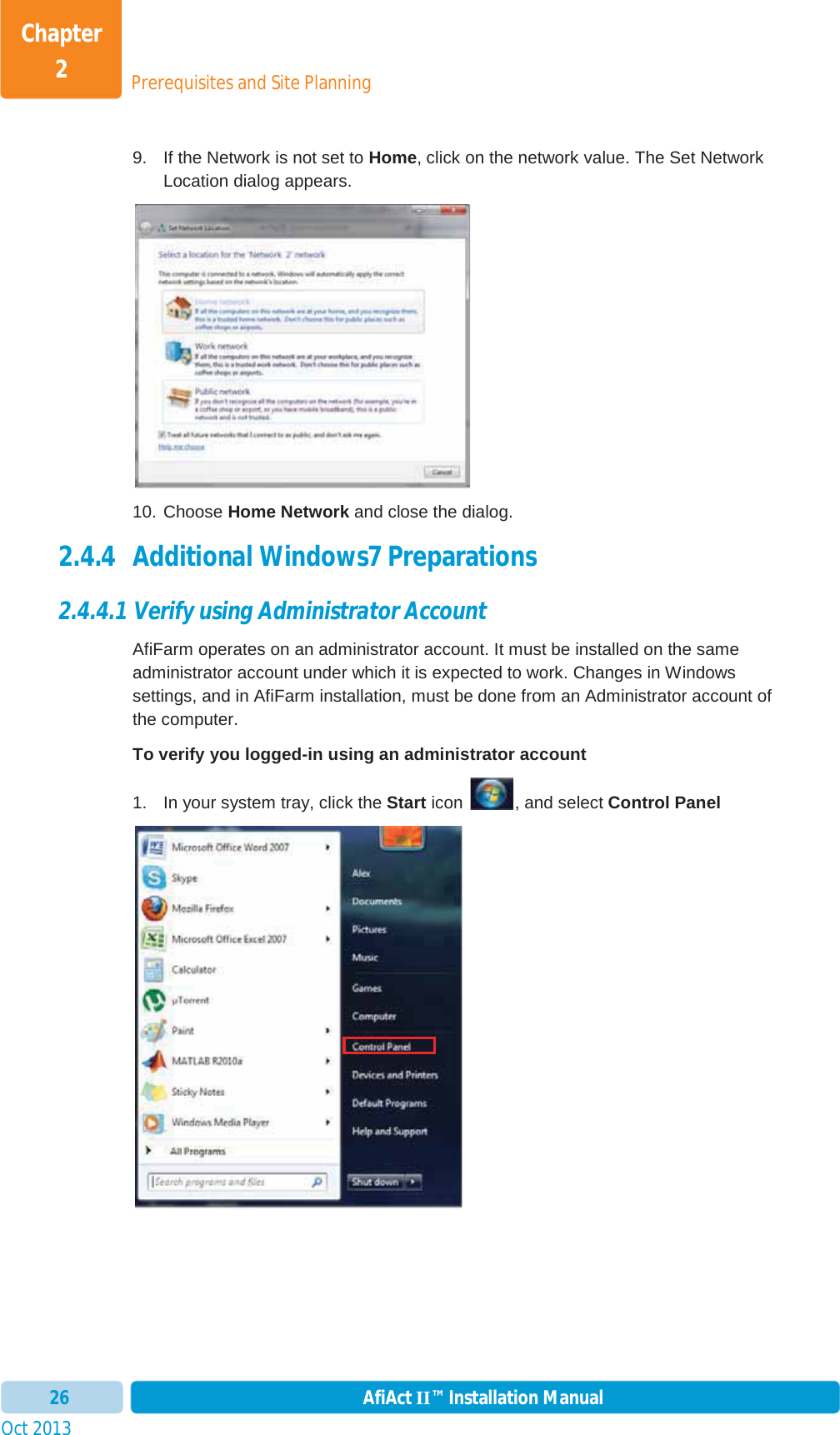
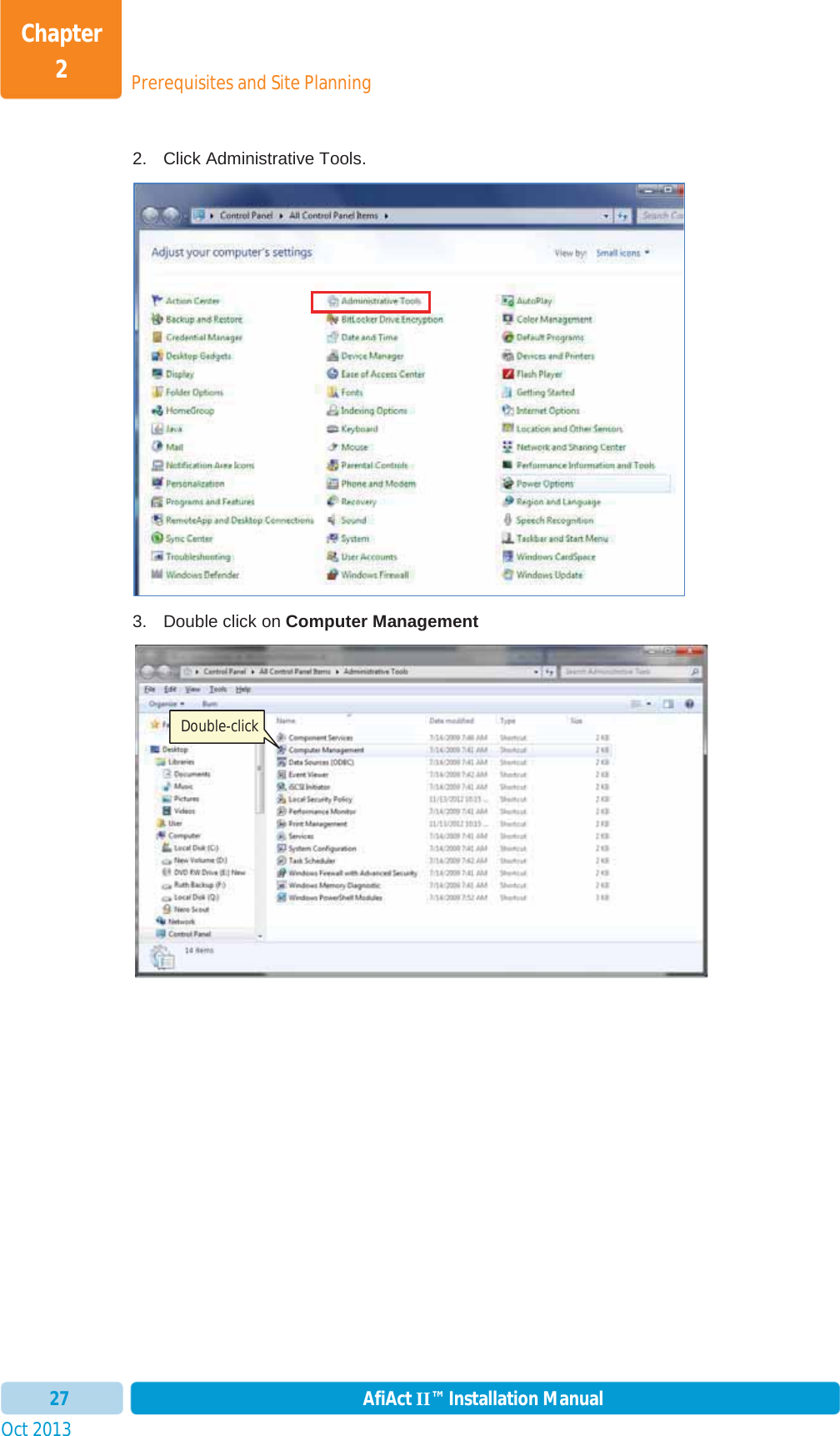
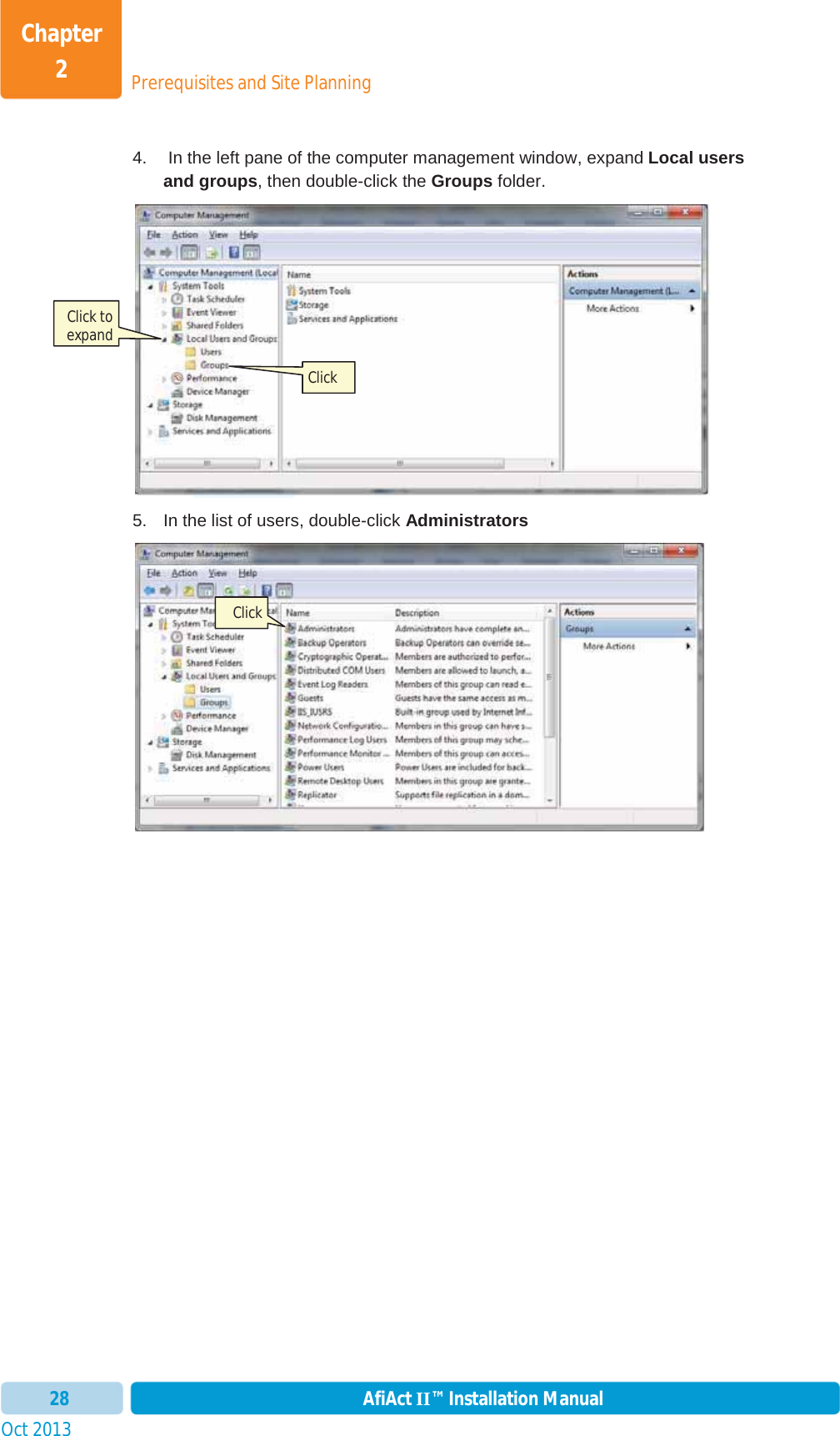
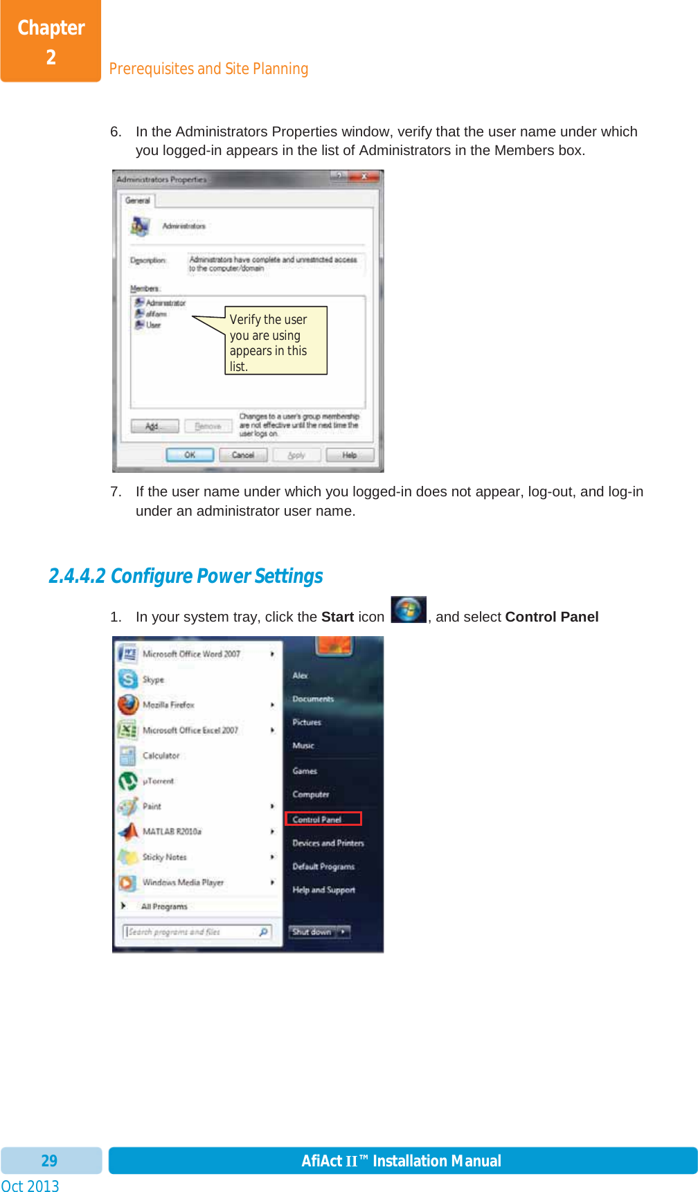
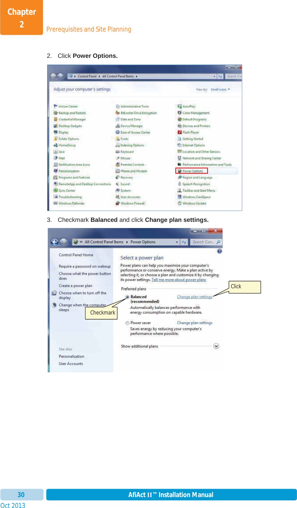
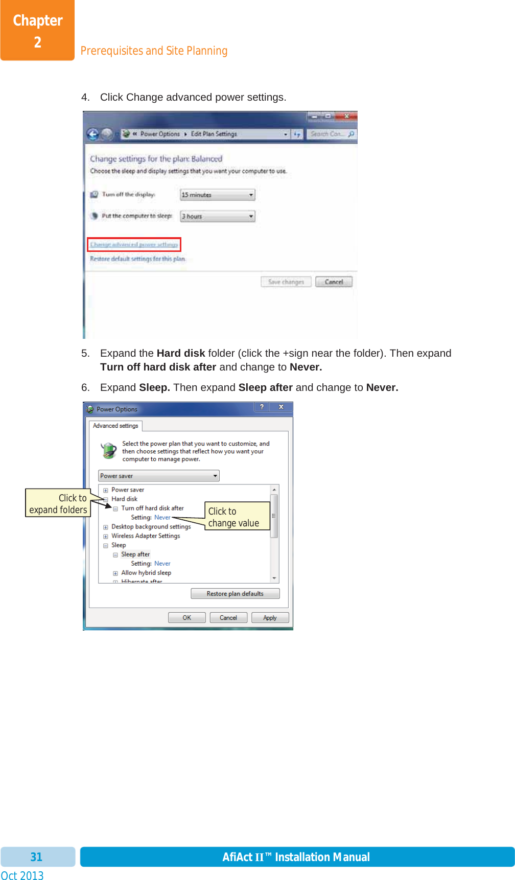
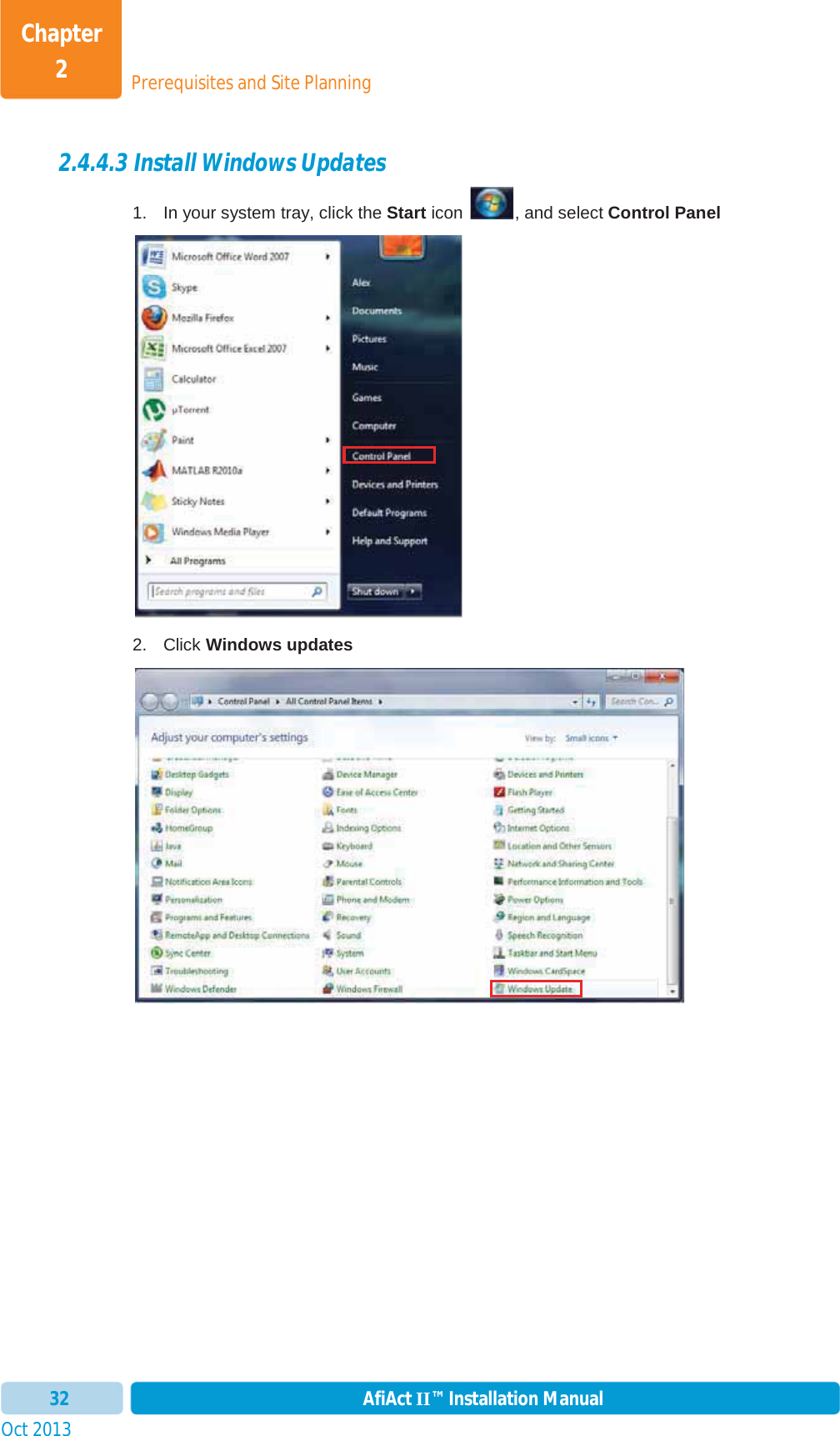
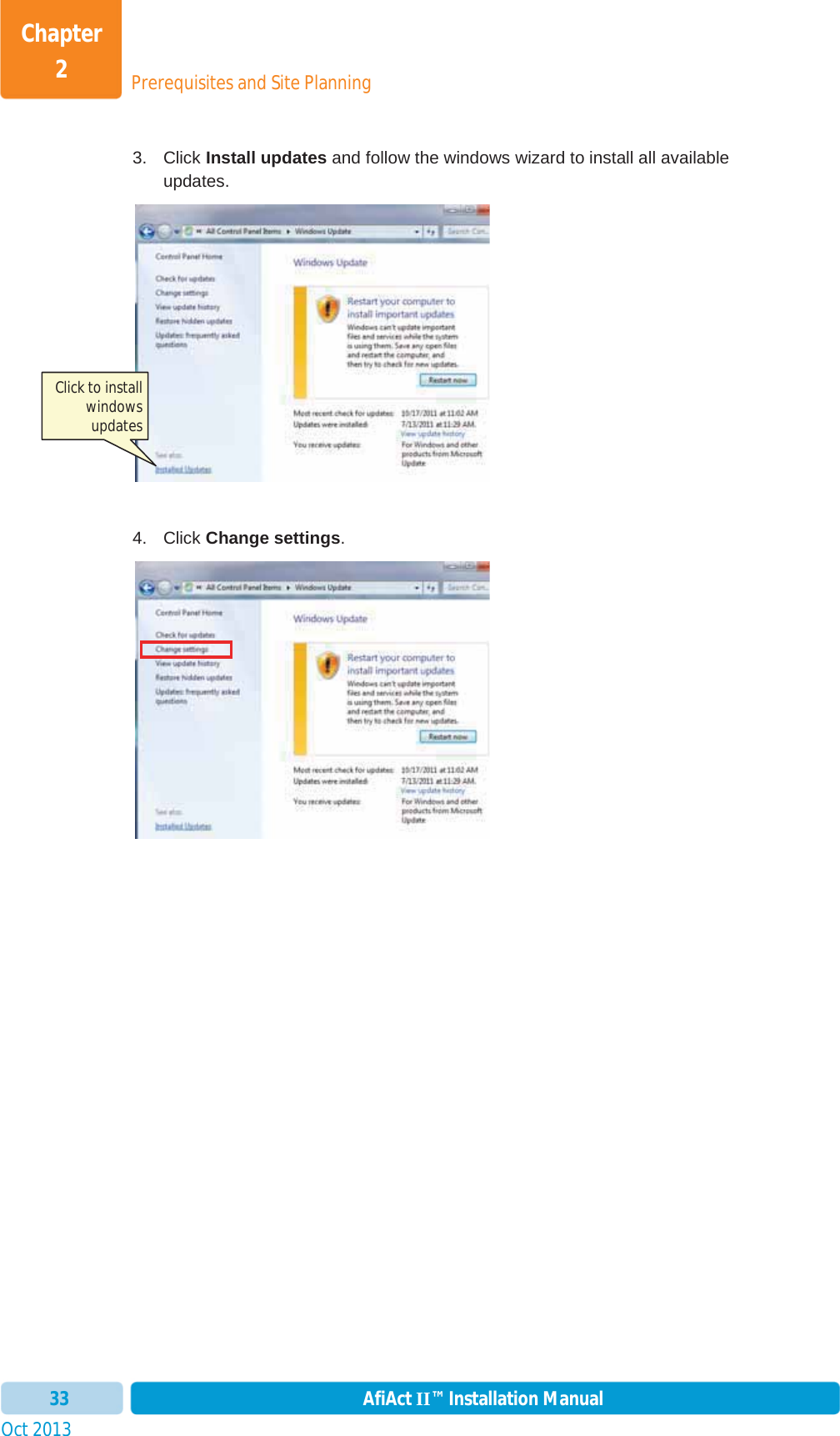
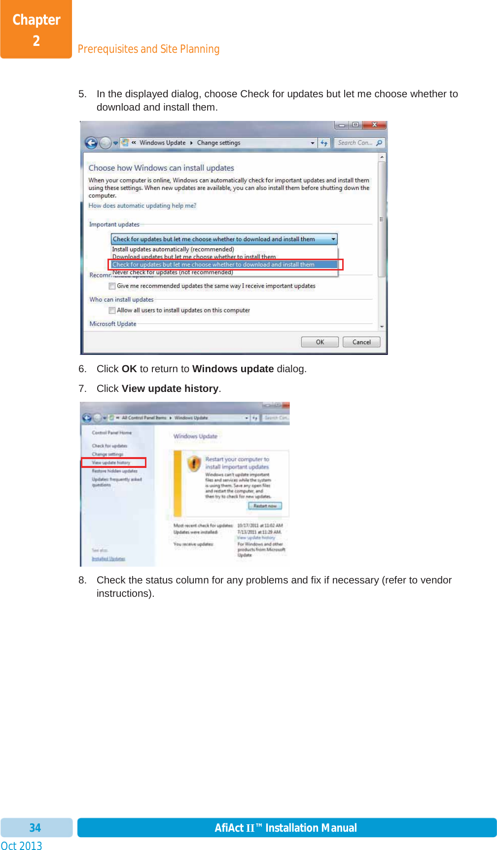
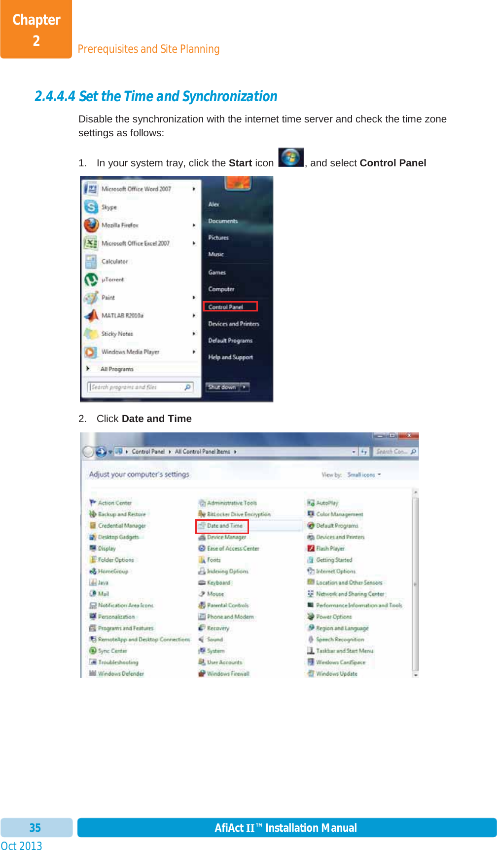
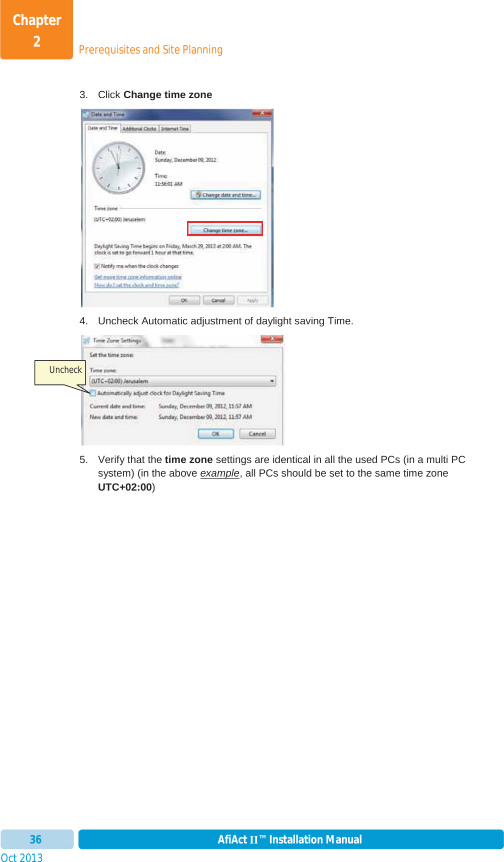
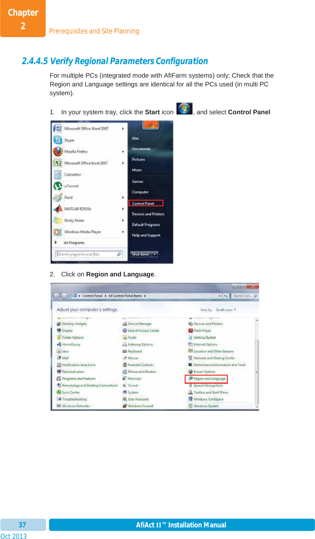
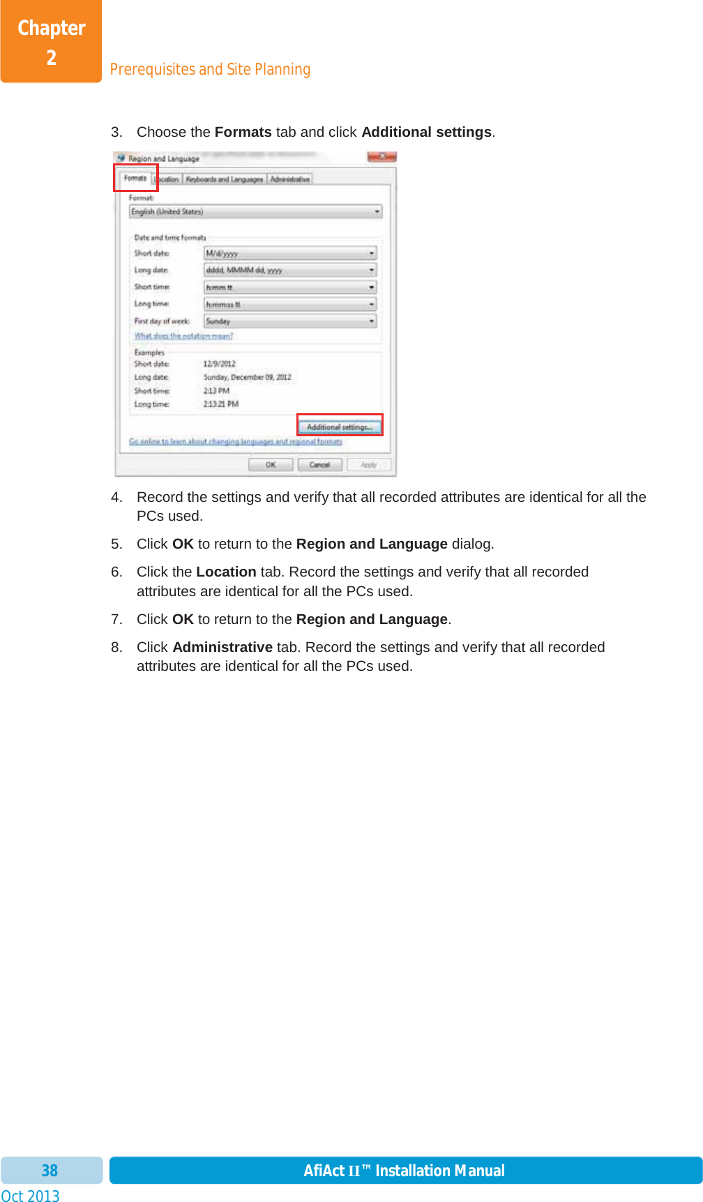
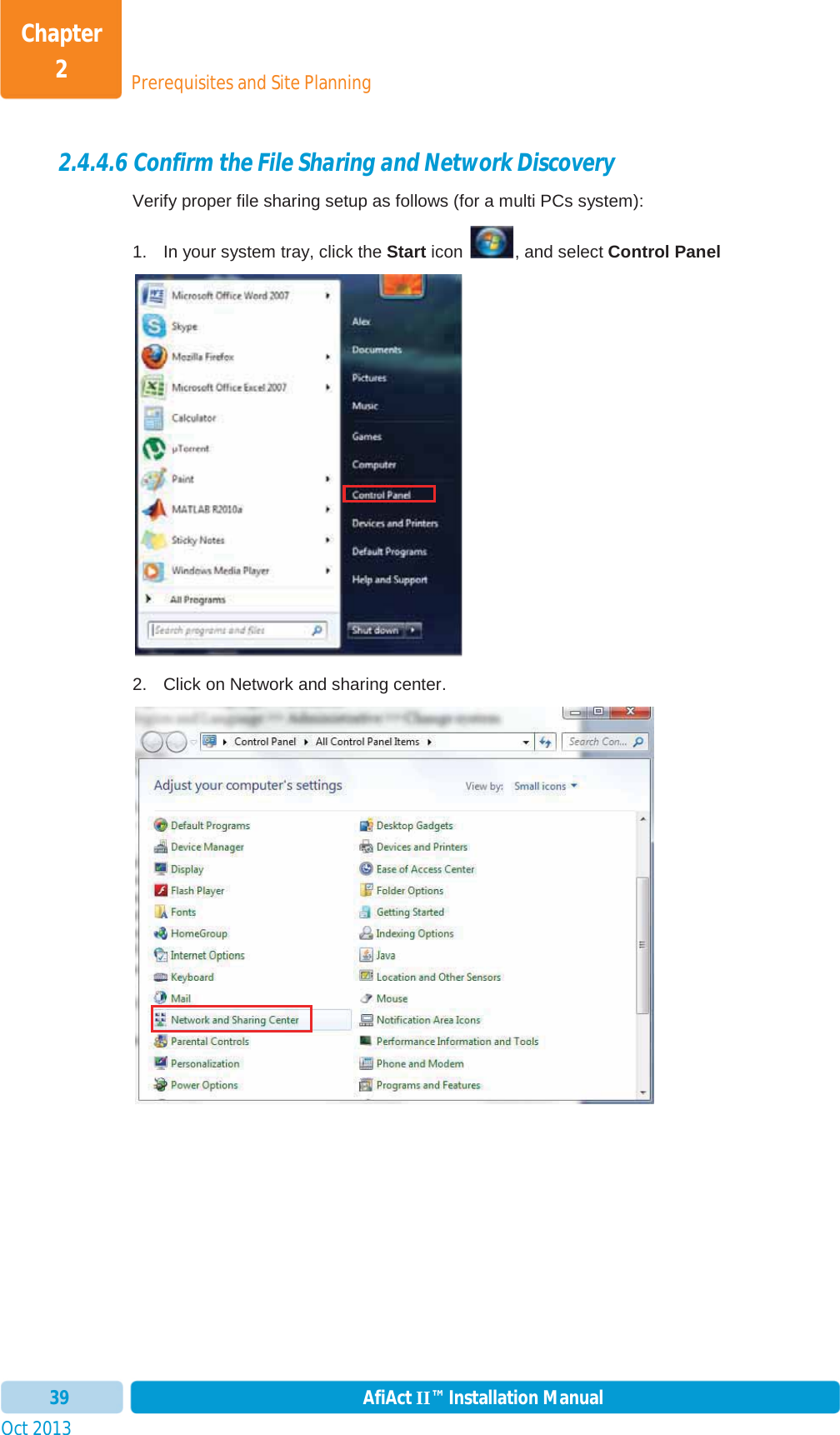
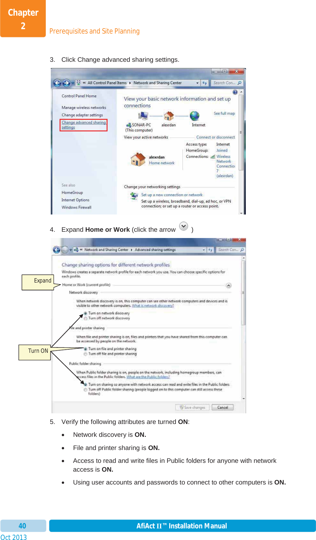
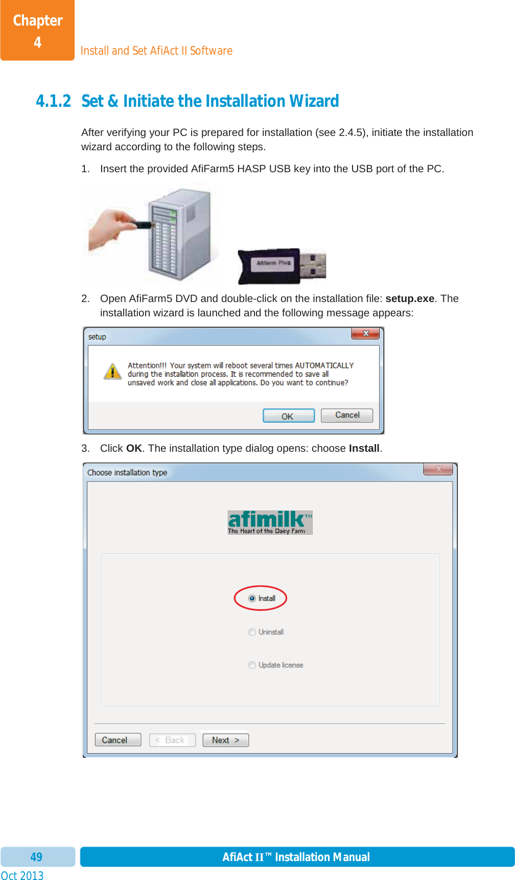
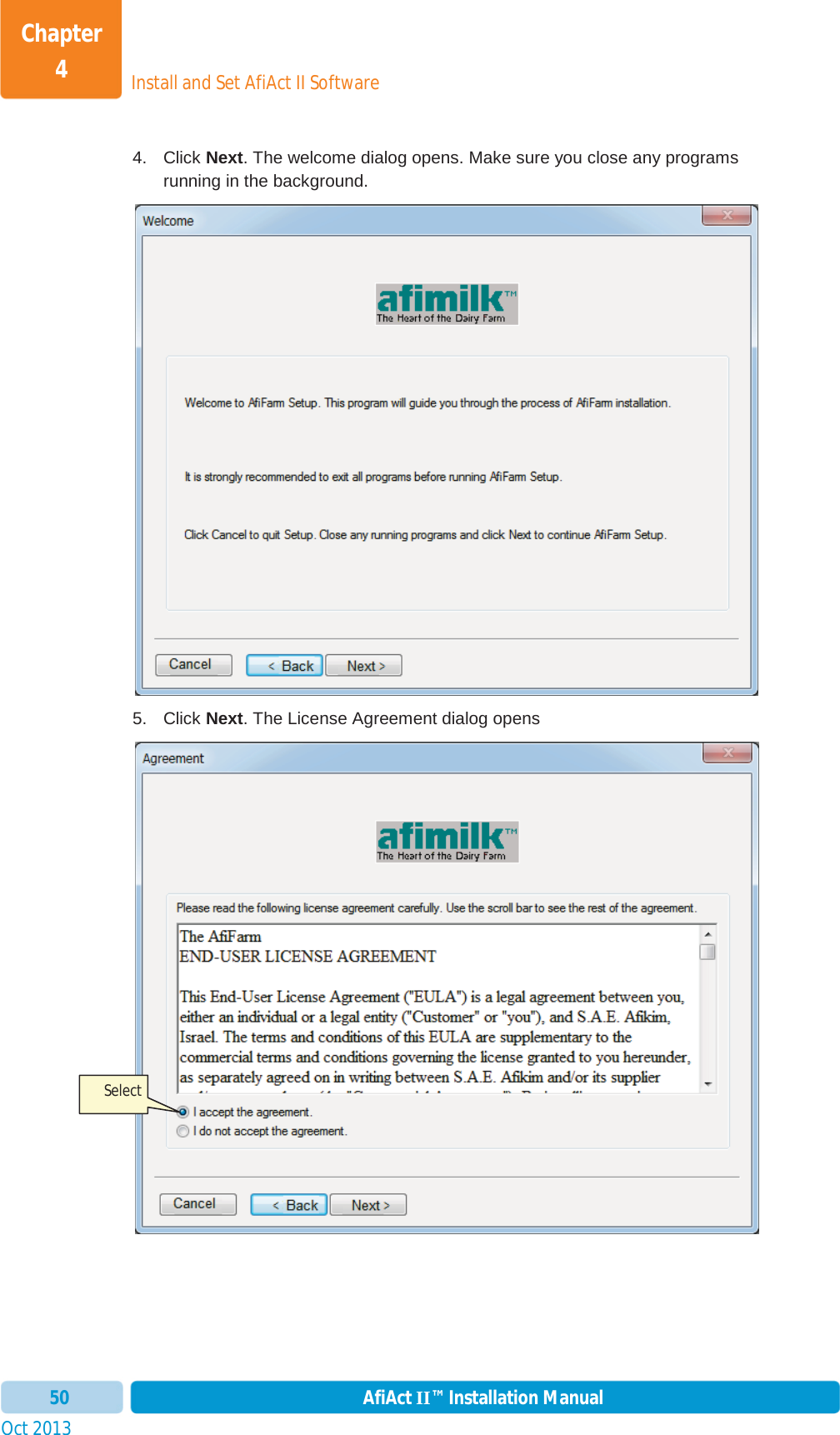
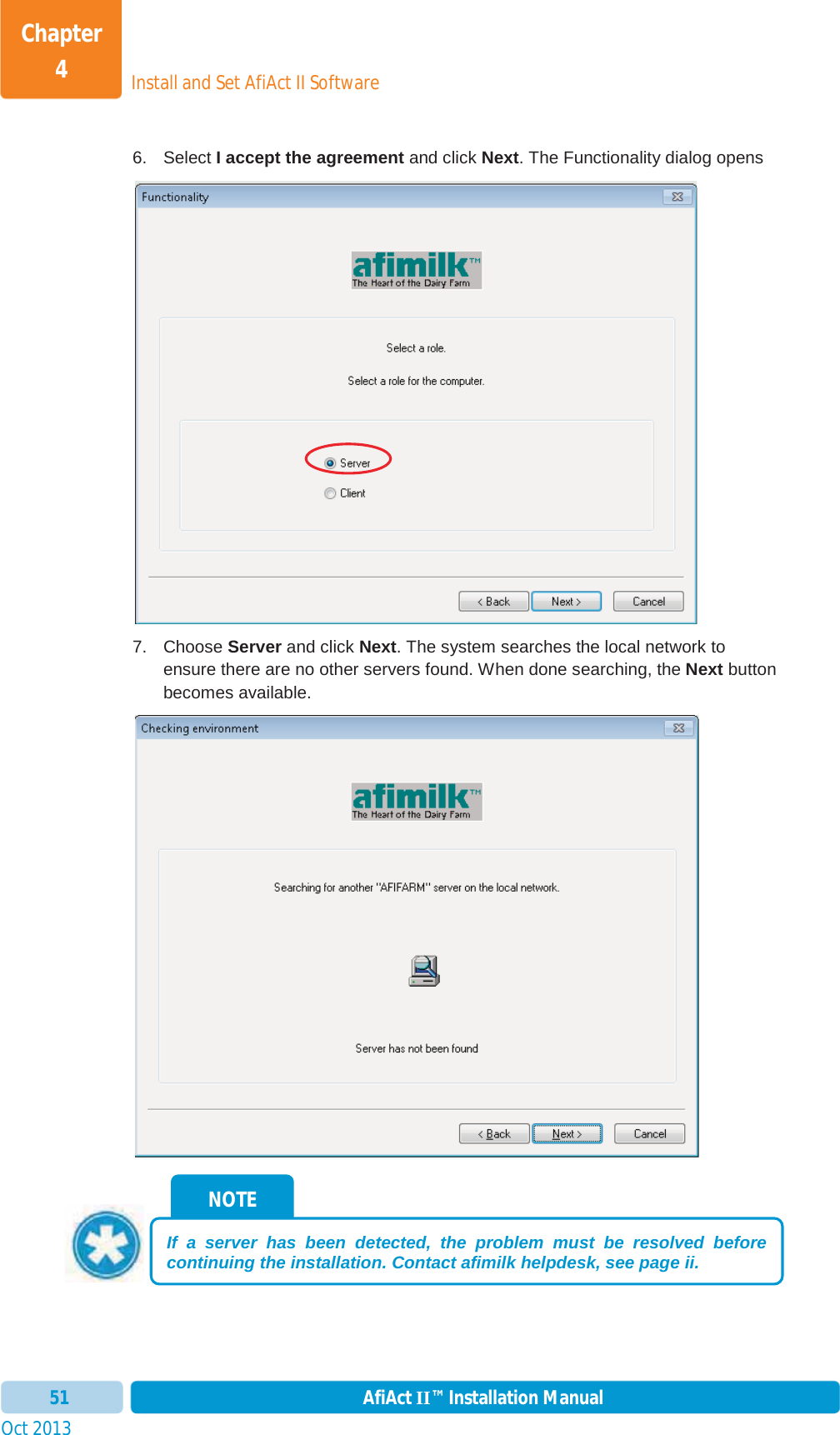
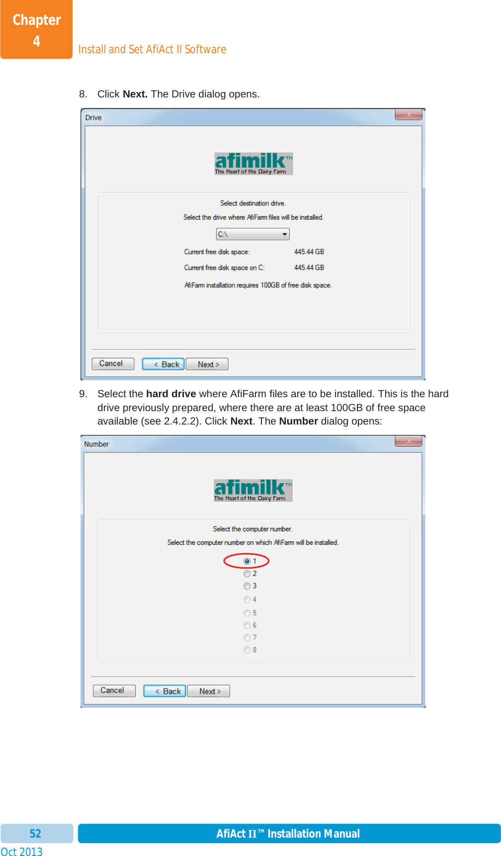
Installation_guide
Contents
1.
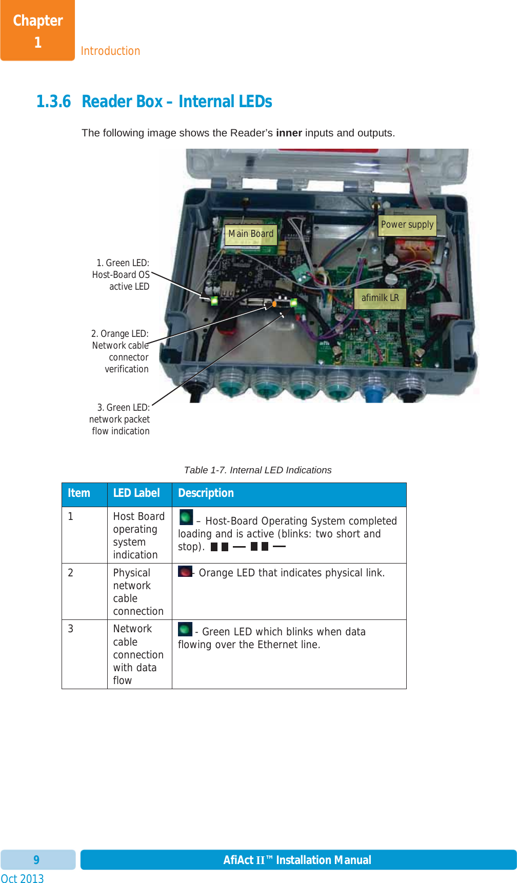
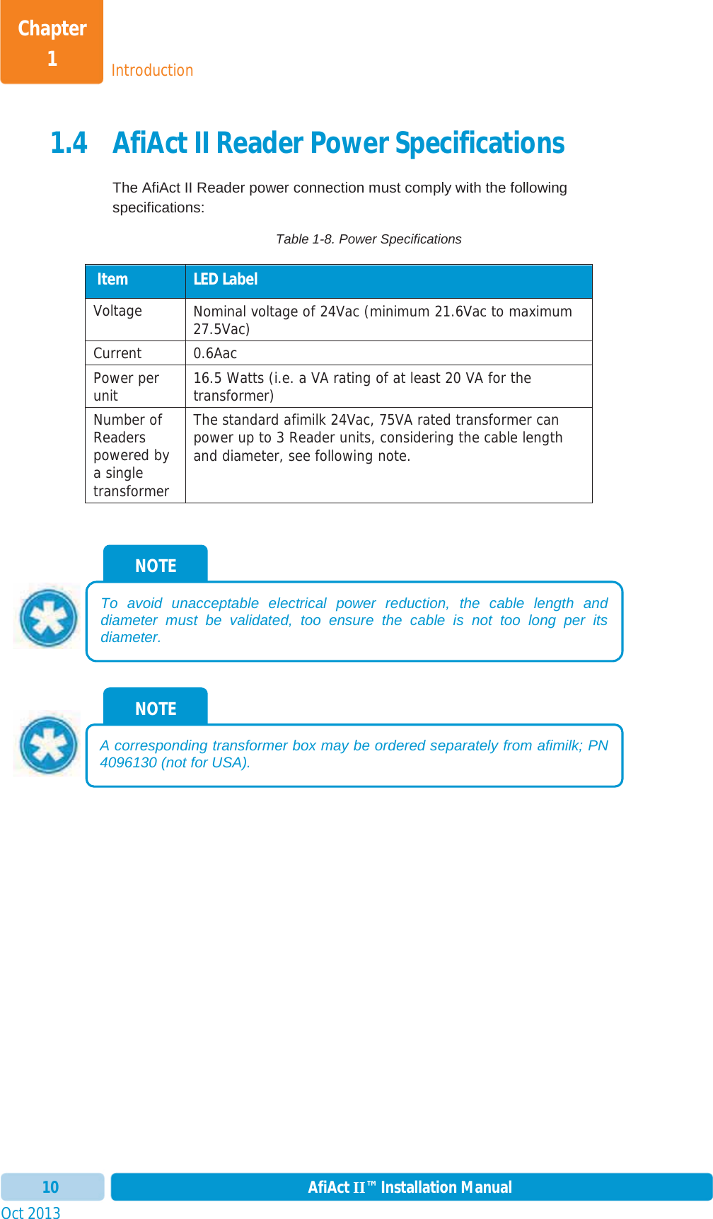
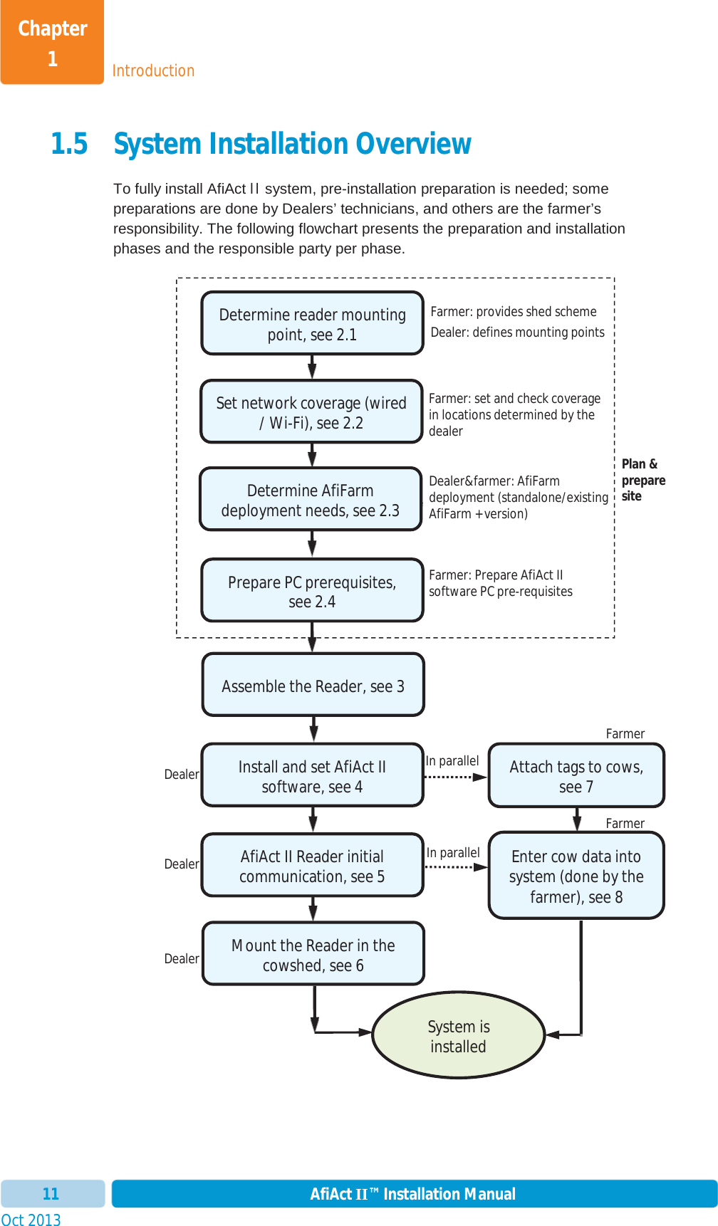
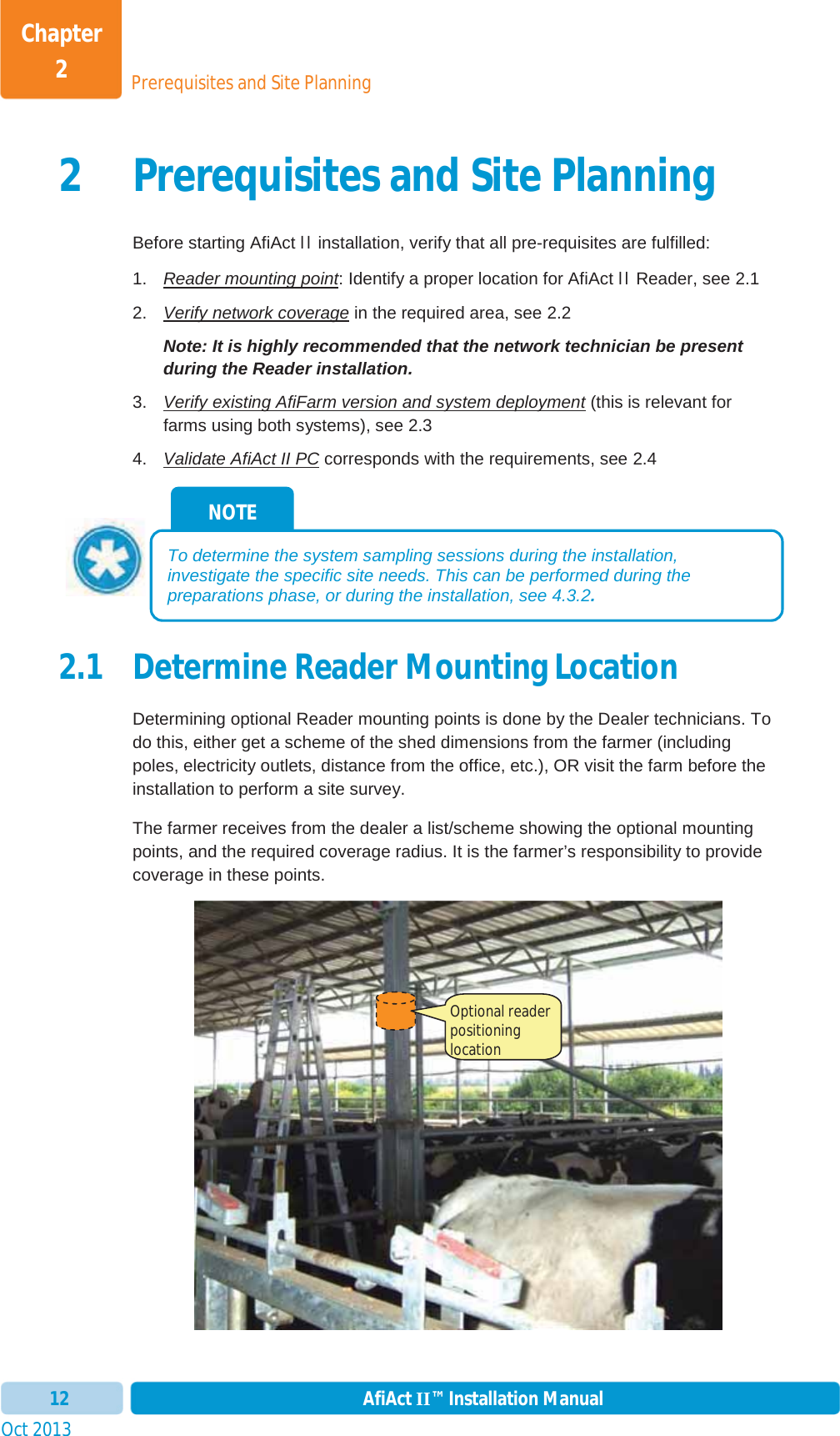
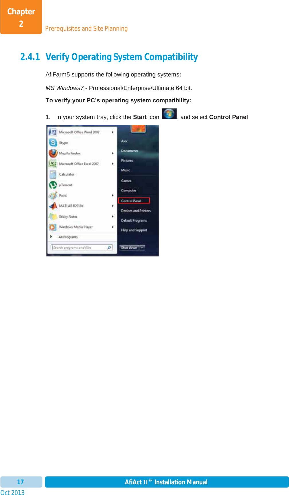
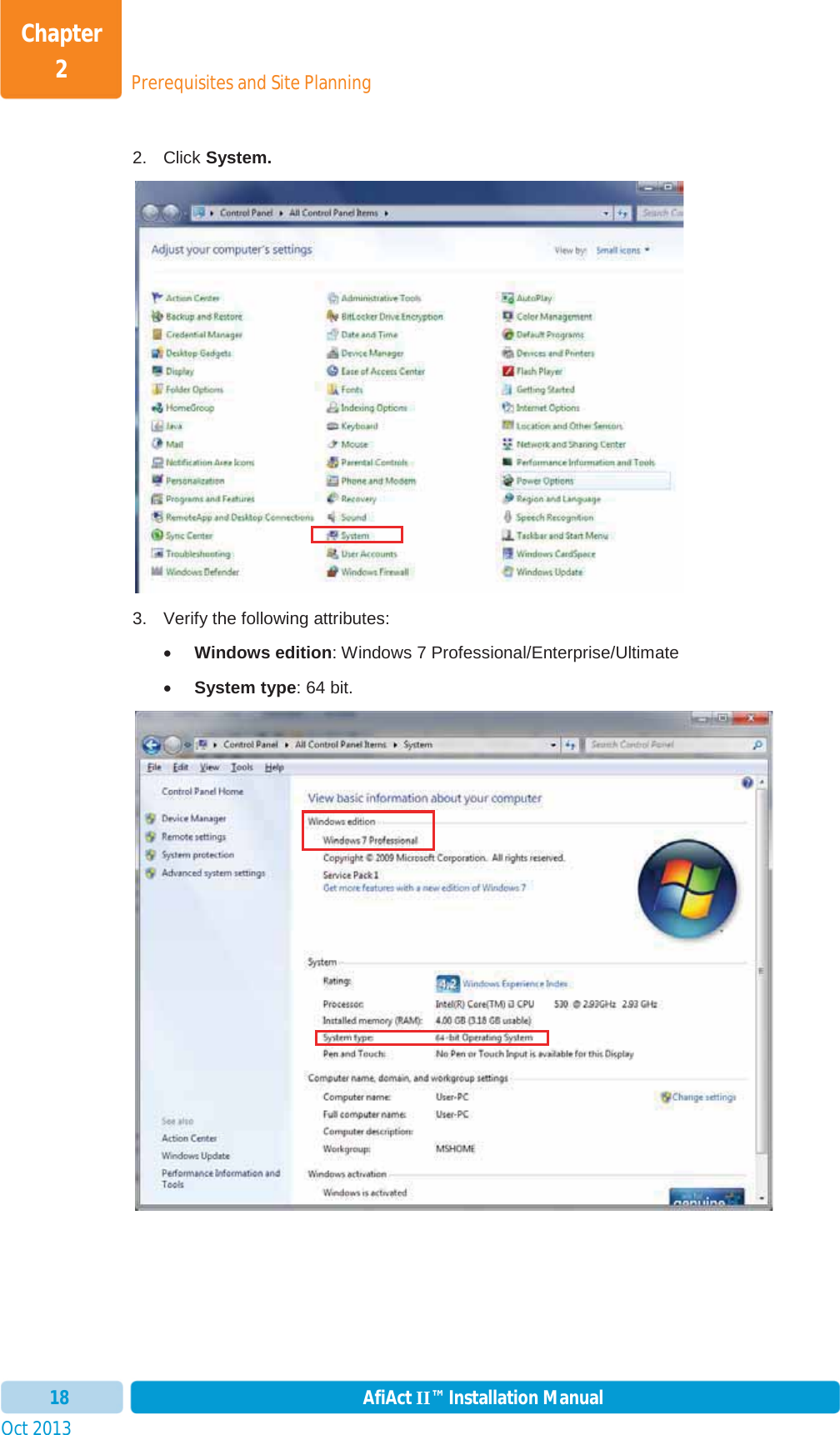
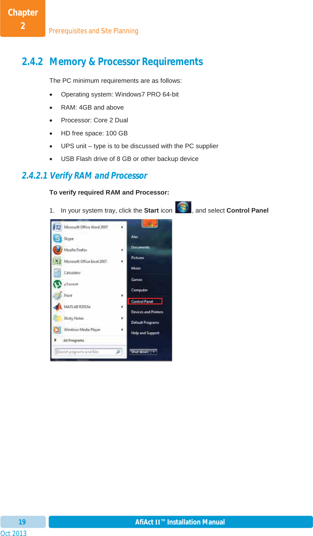
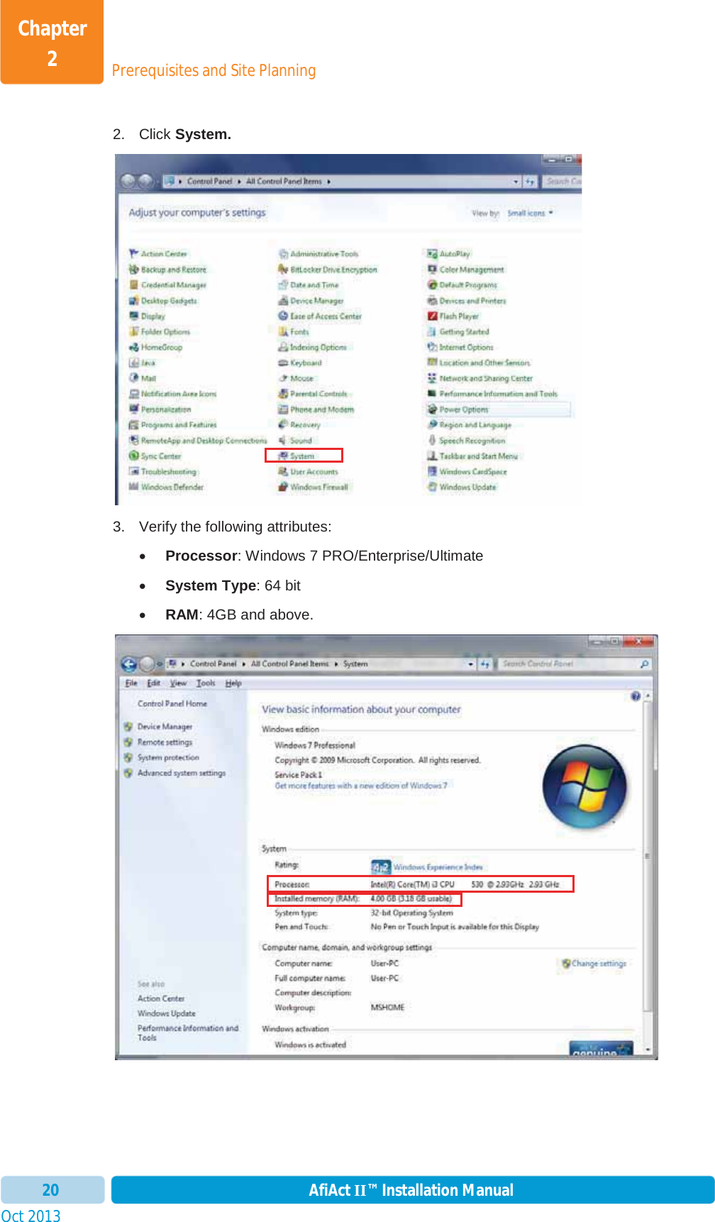
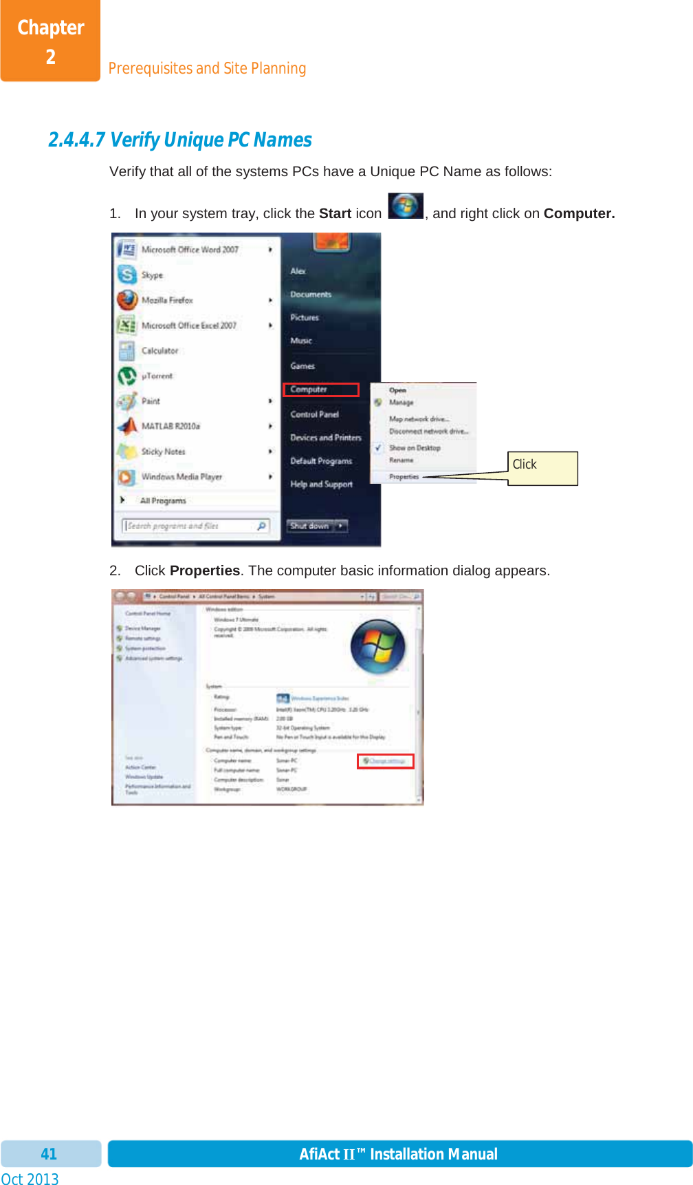
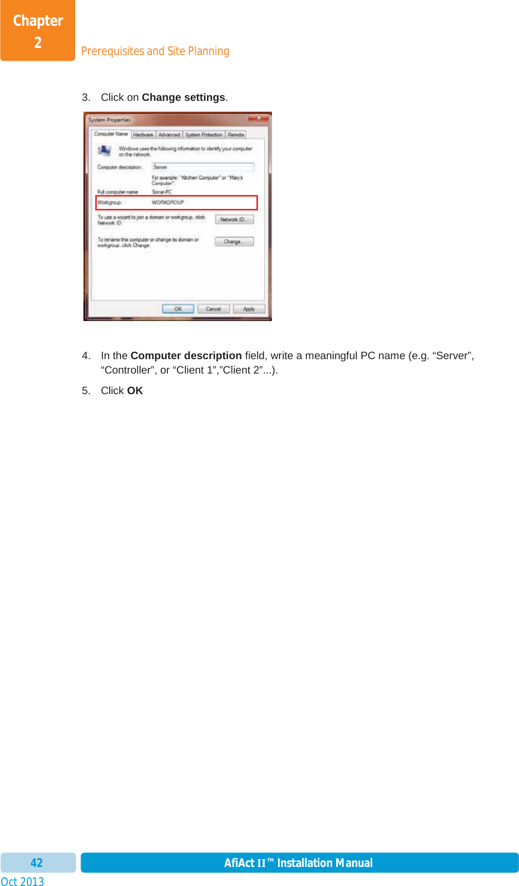
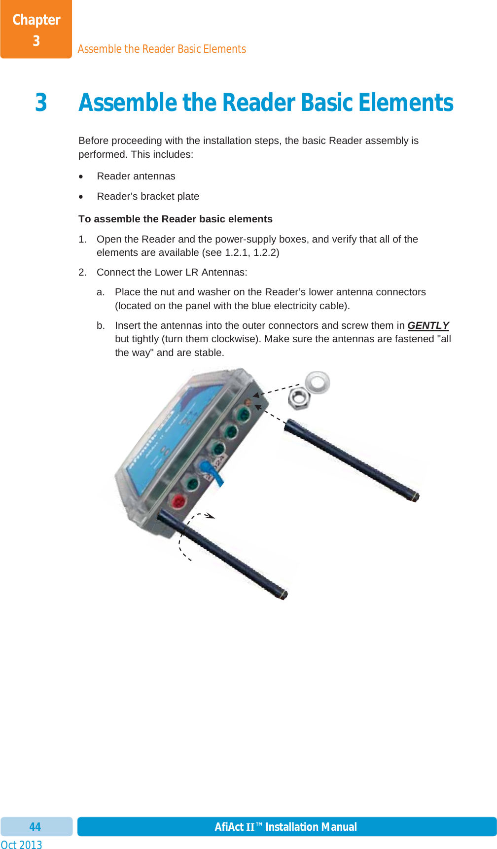
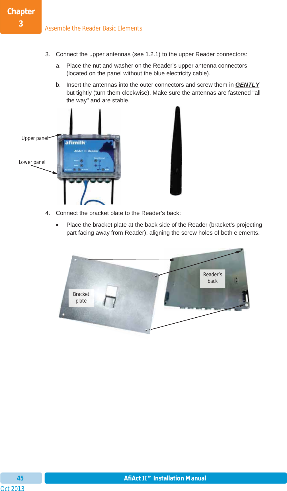
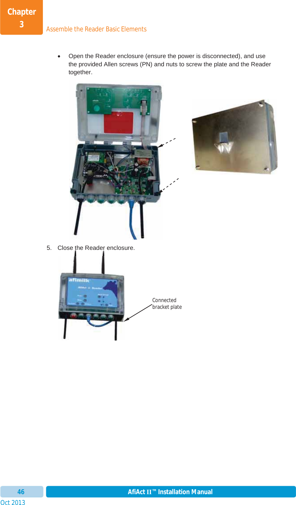
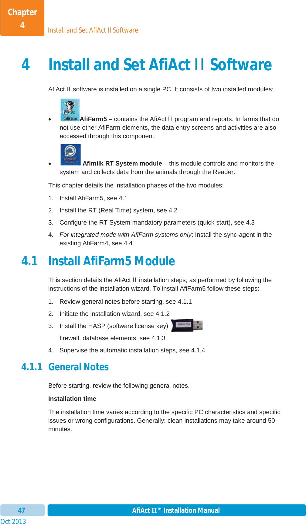
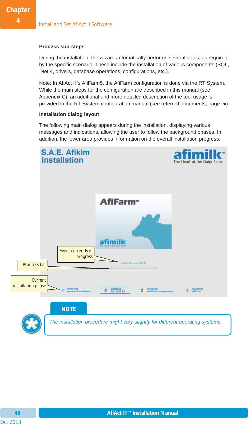
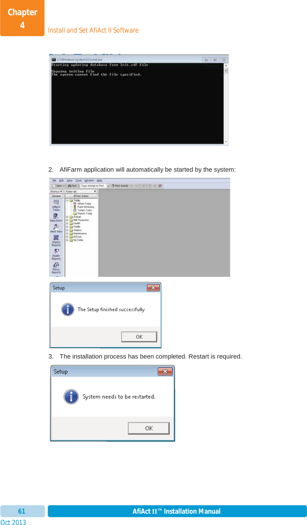
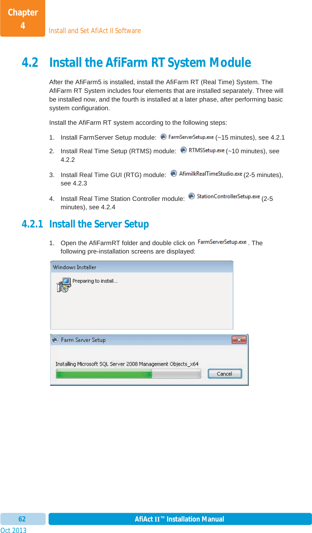
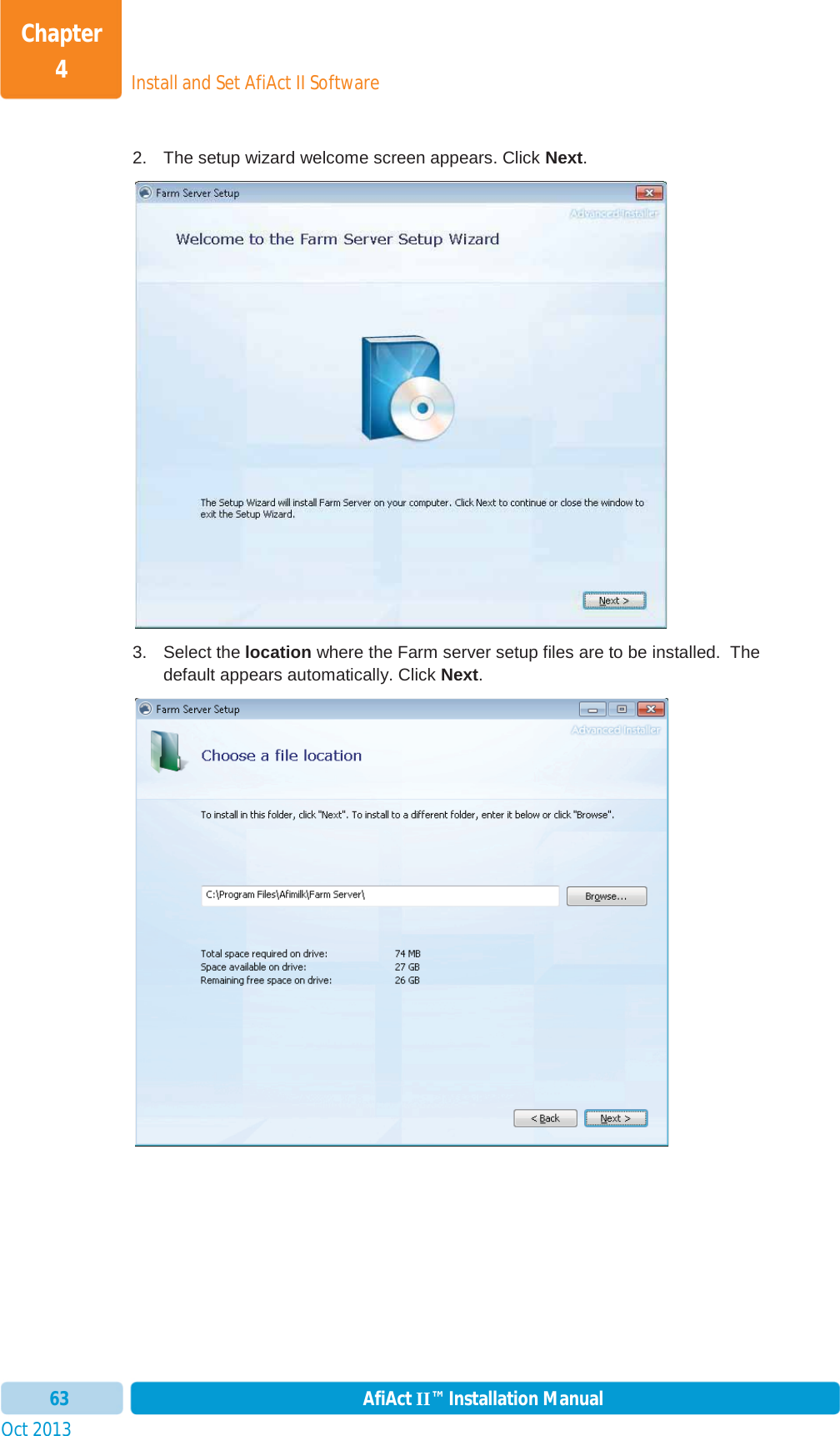
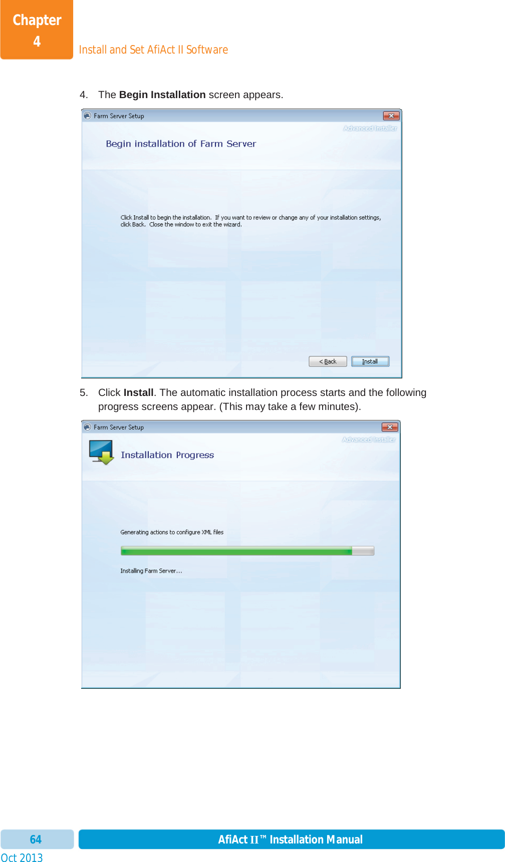
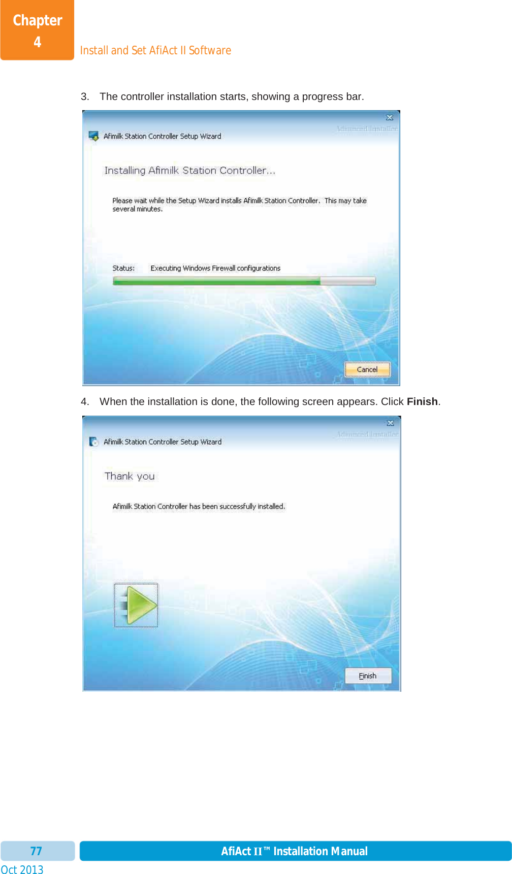
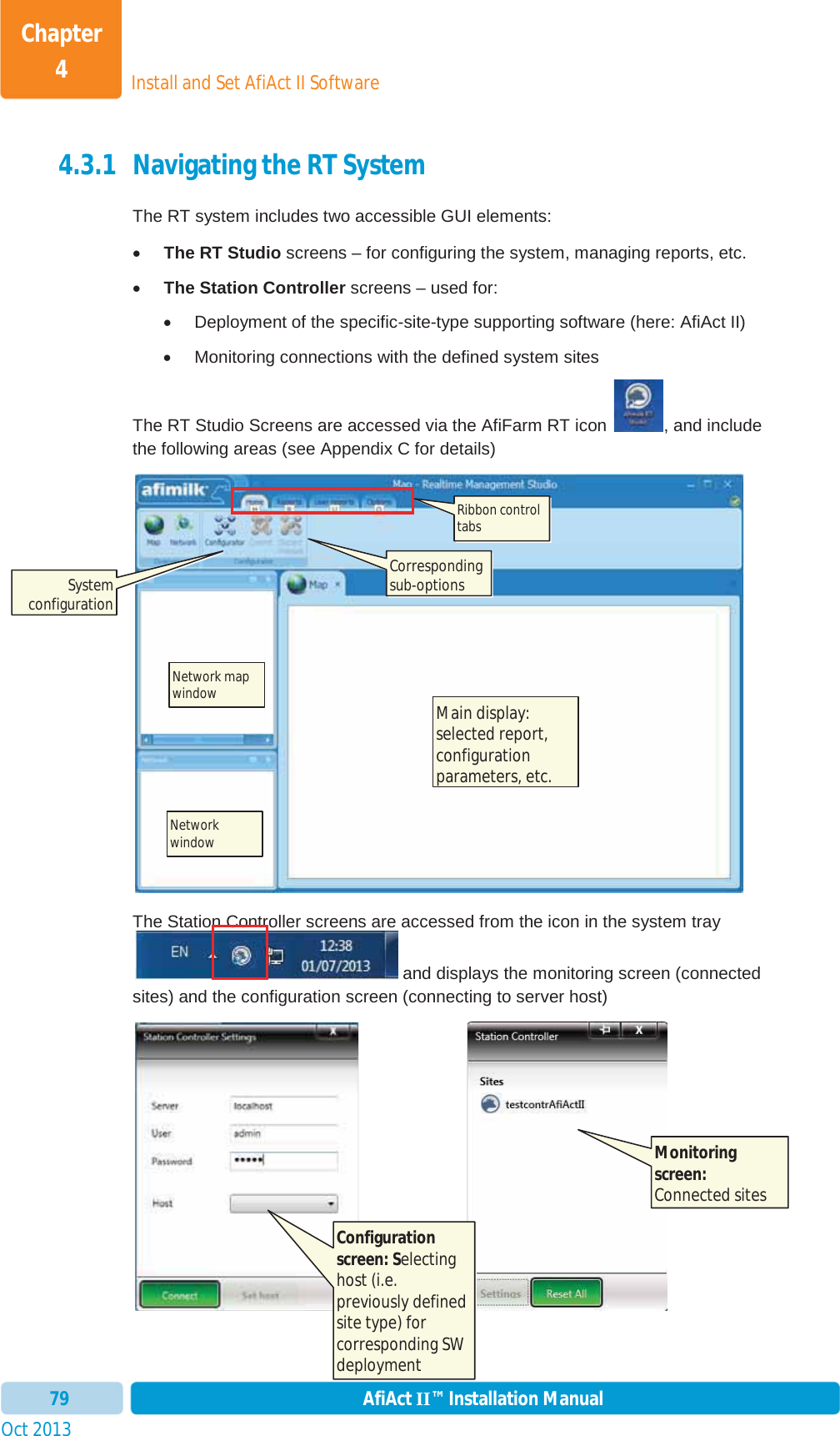
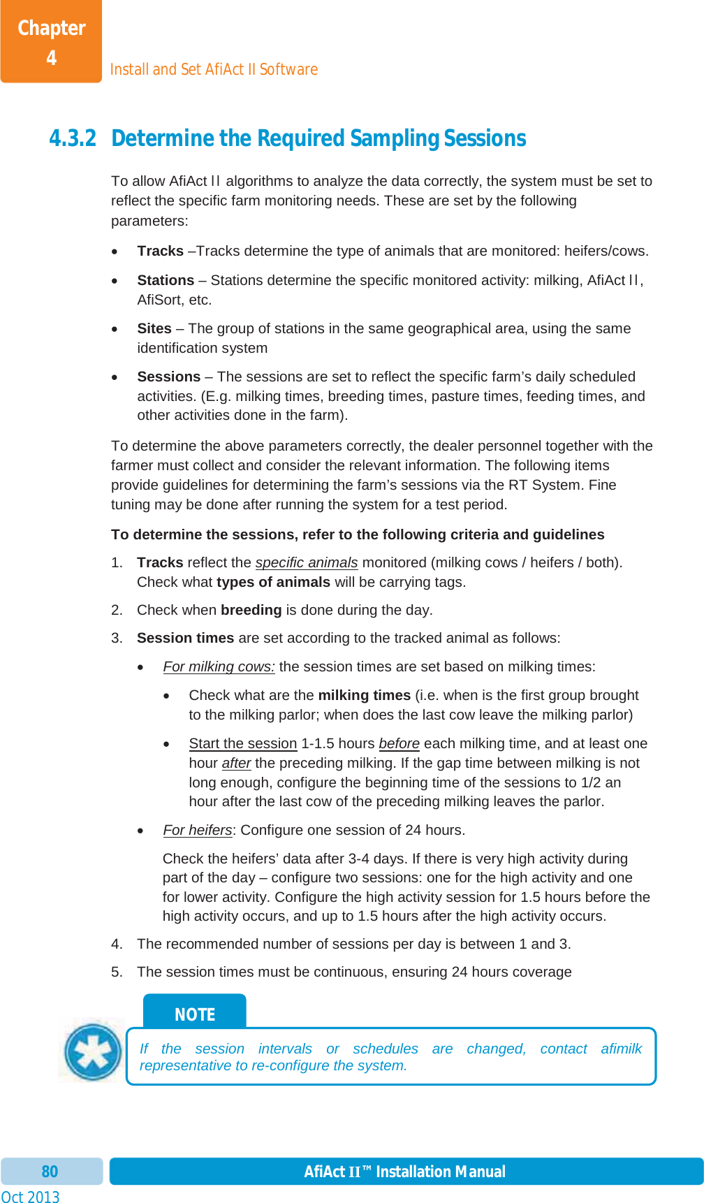
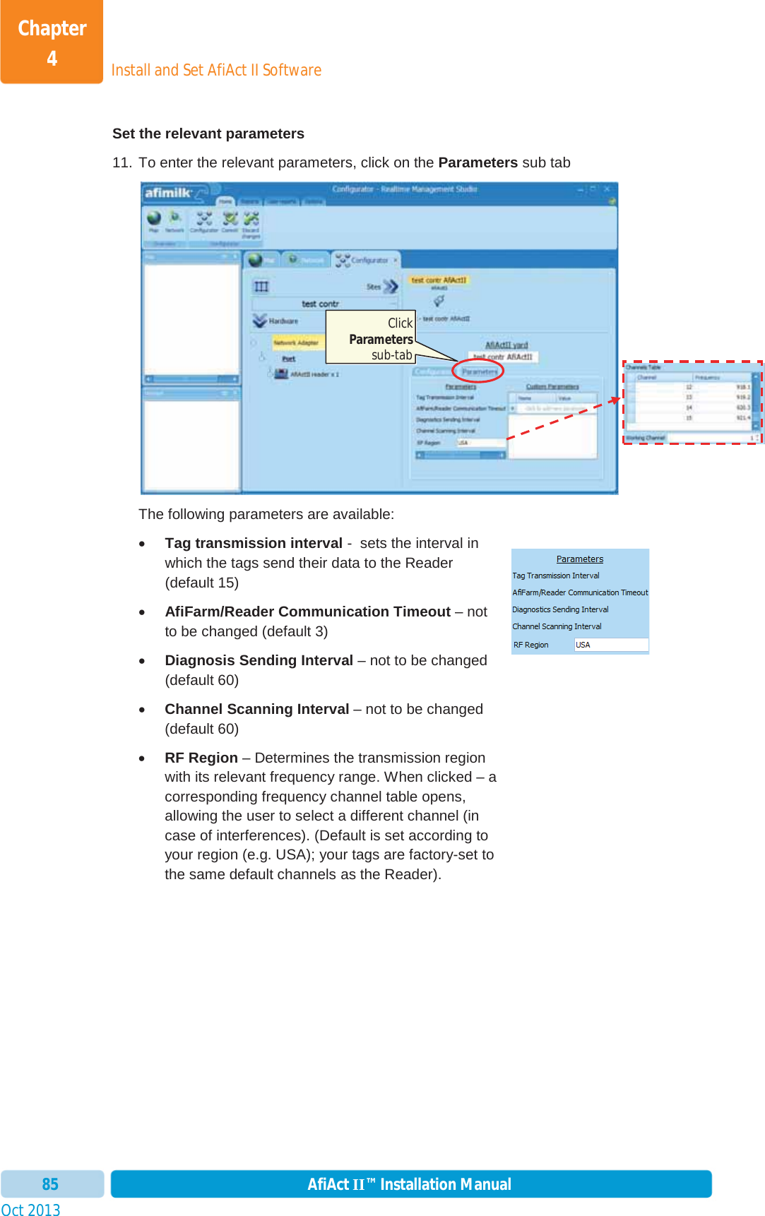
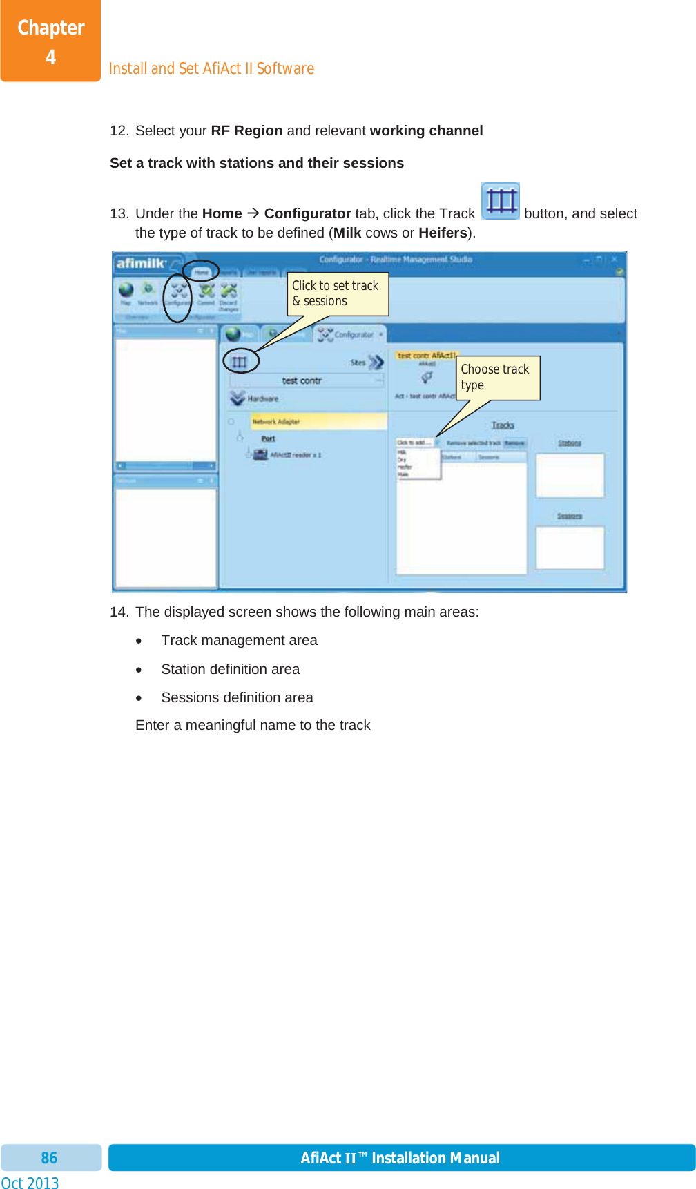
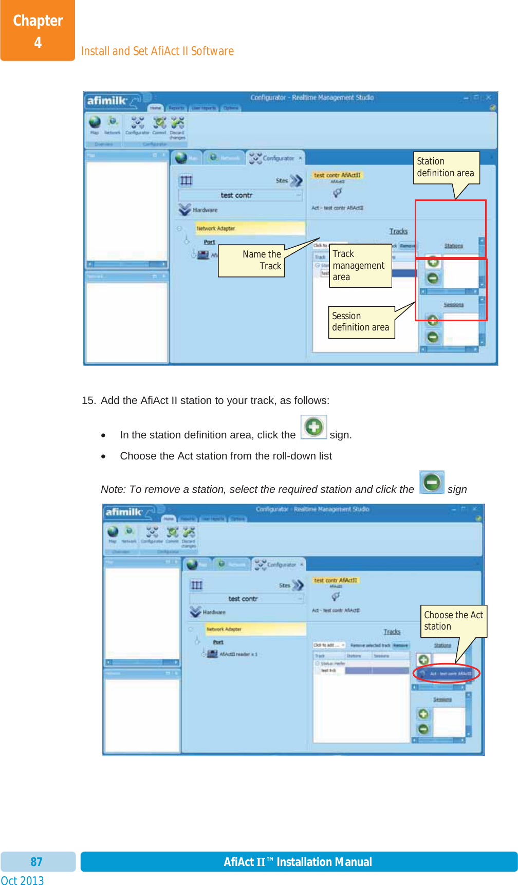
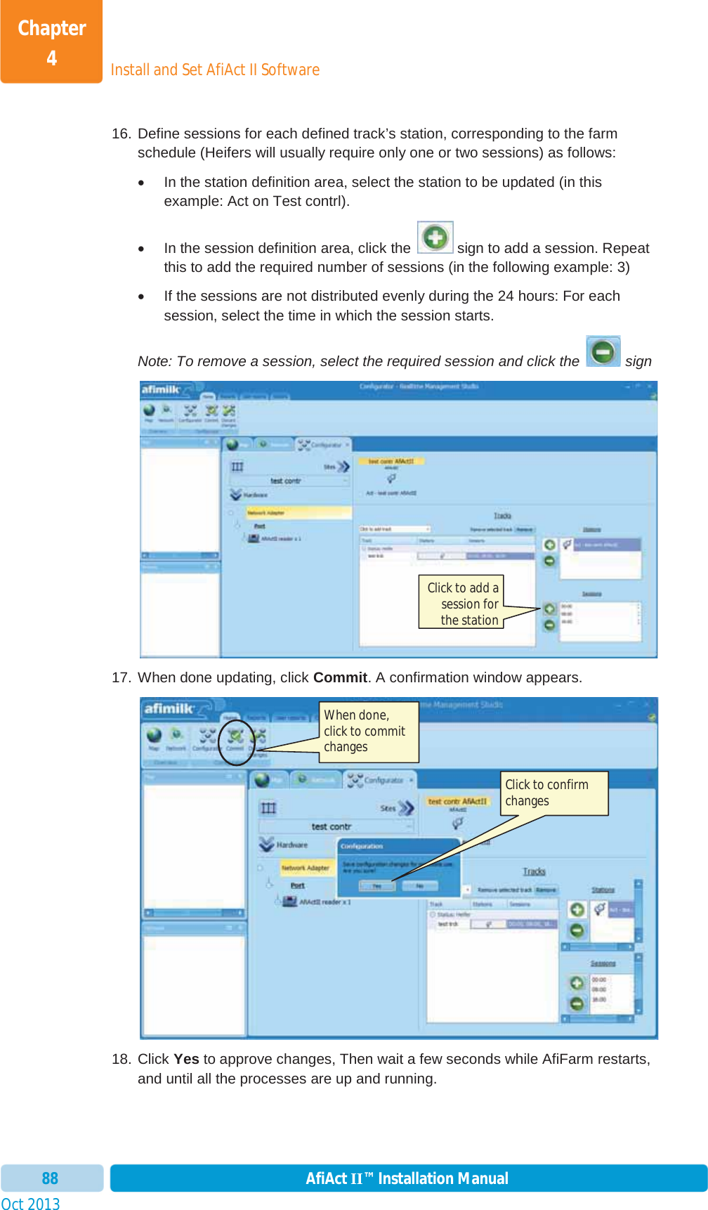
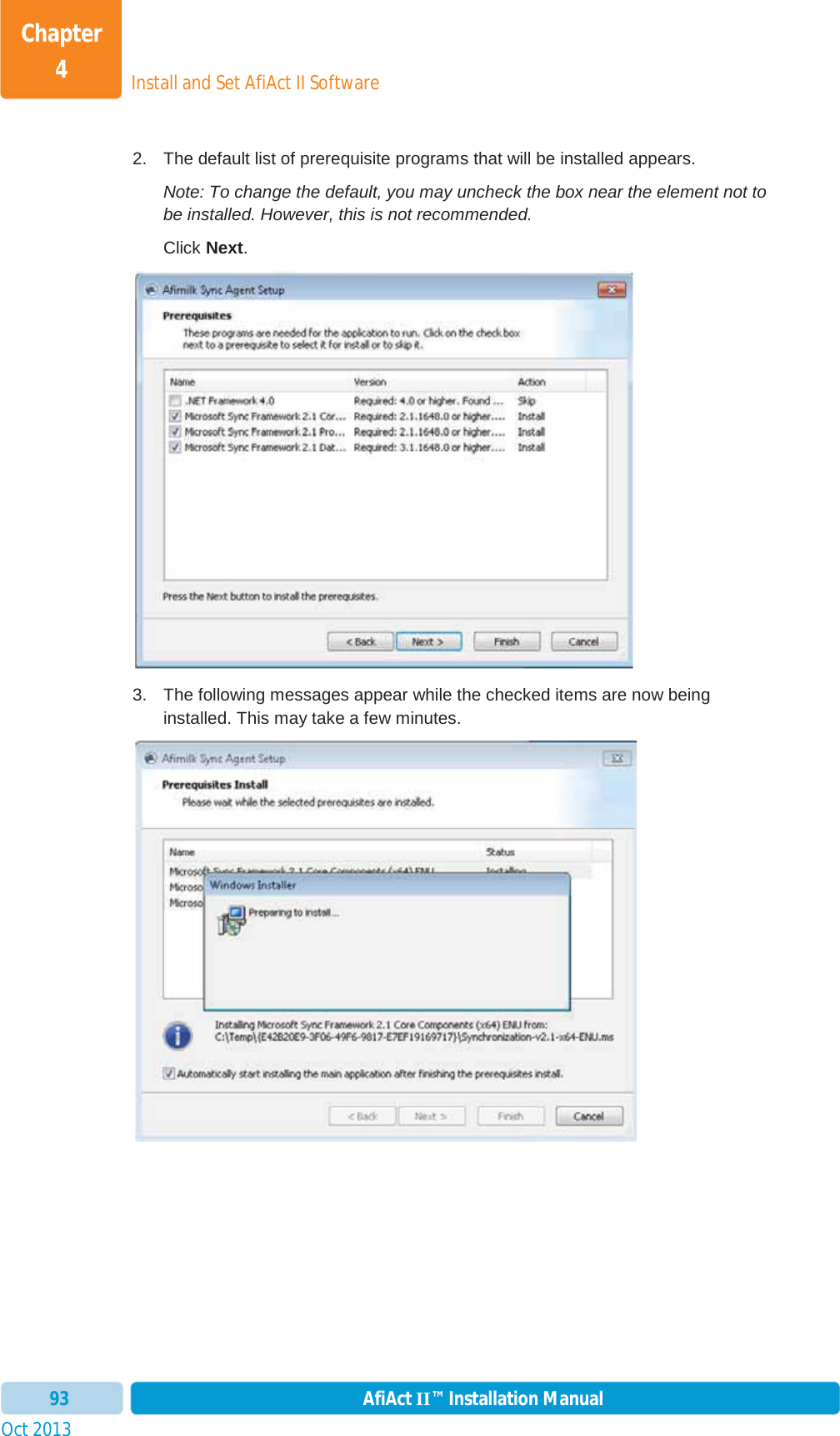
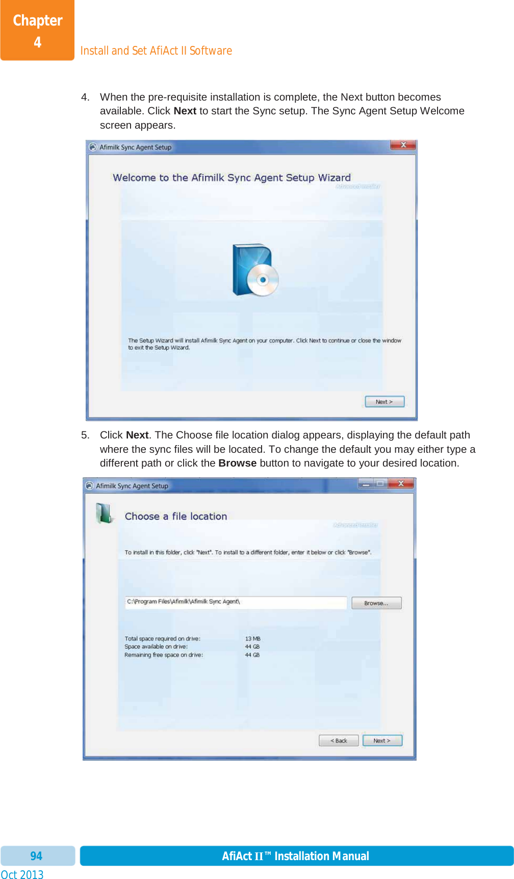
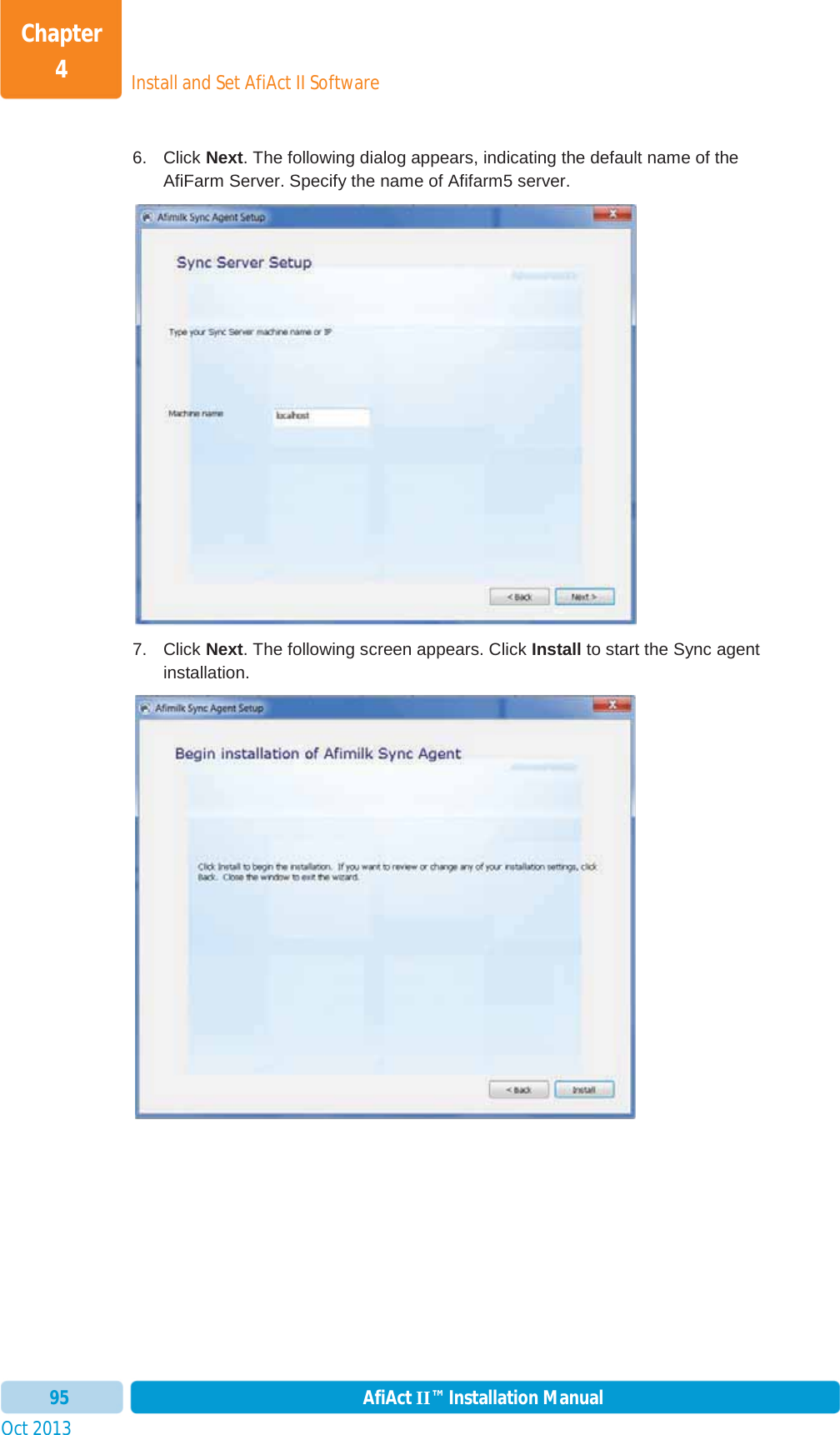
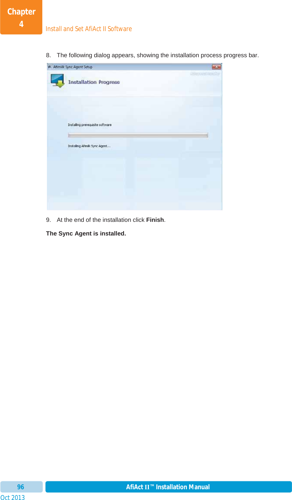
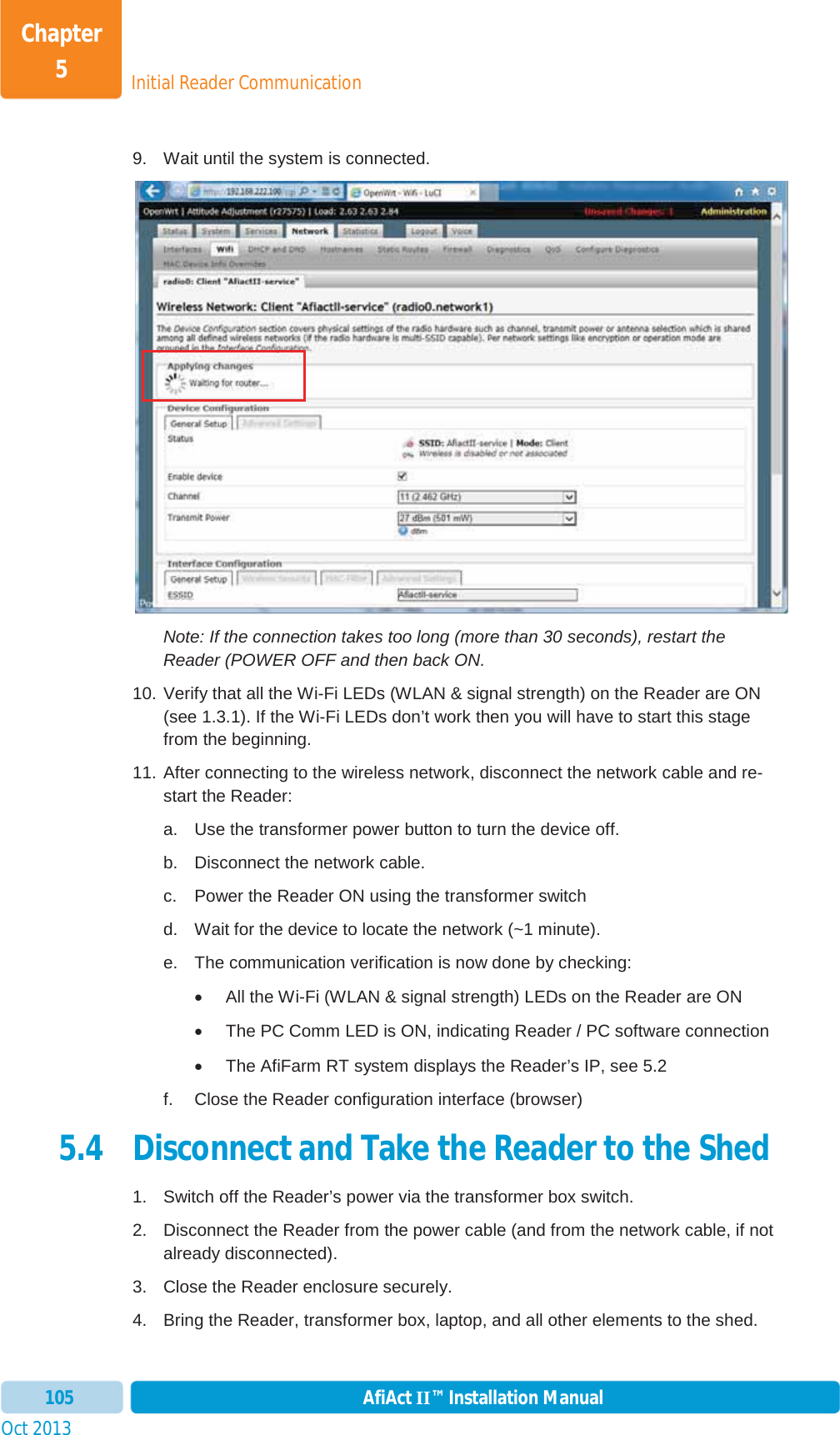
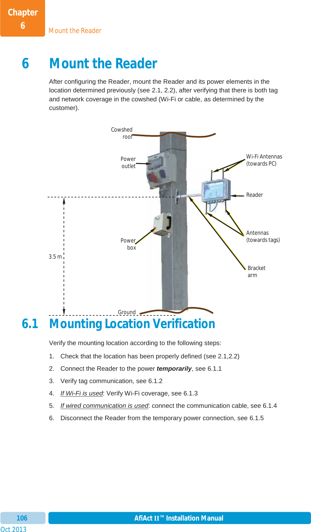
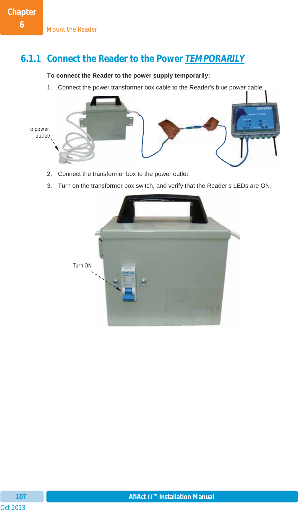
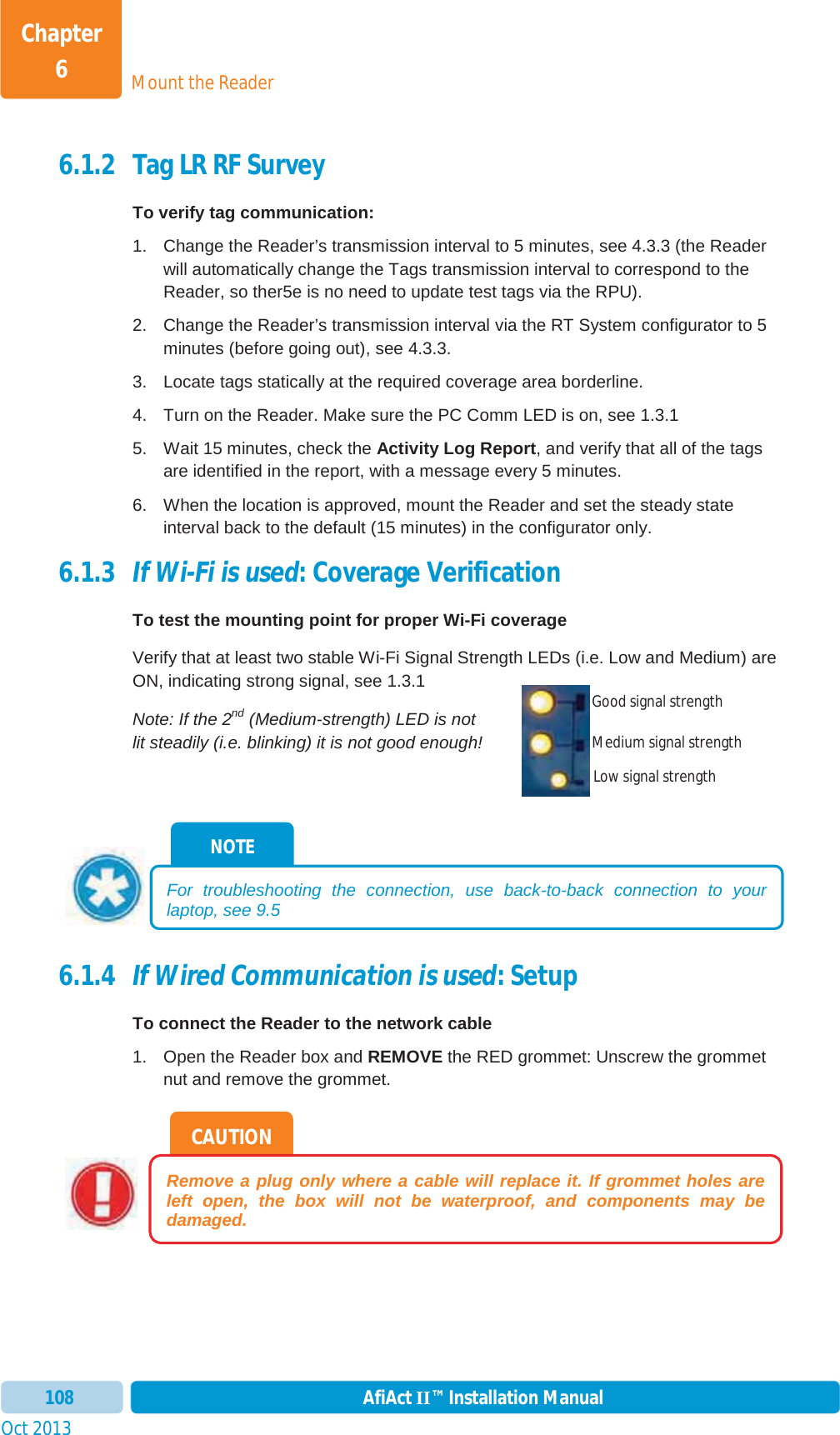
Installation_guide
2.
user manual
Installation_guide
Navigation menu
Upload a User Manual
Namespaces
Wiki Guide
HTML
PDF
Info
Views
User Manual
Discussion / Help
Navigation