Agere Systems Nederland WLPC2411R 2.4 GHz low power WLAN integrated PCMCIA card User Manual ORiNOCO Outdoor Antenna Installation Guide
Agere Systems Nederland B.V. 2.4 GHz low power WLAN integrated PCMCIA card ORiNOCO Outdoor Antenna Installation Guide
Contents
- 1. User manual
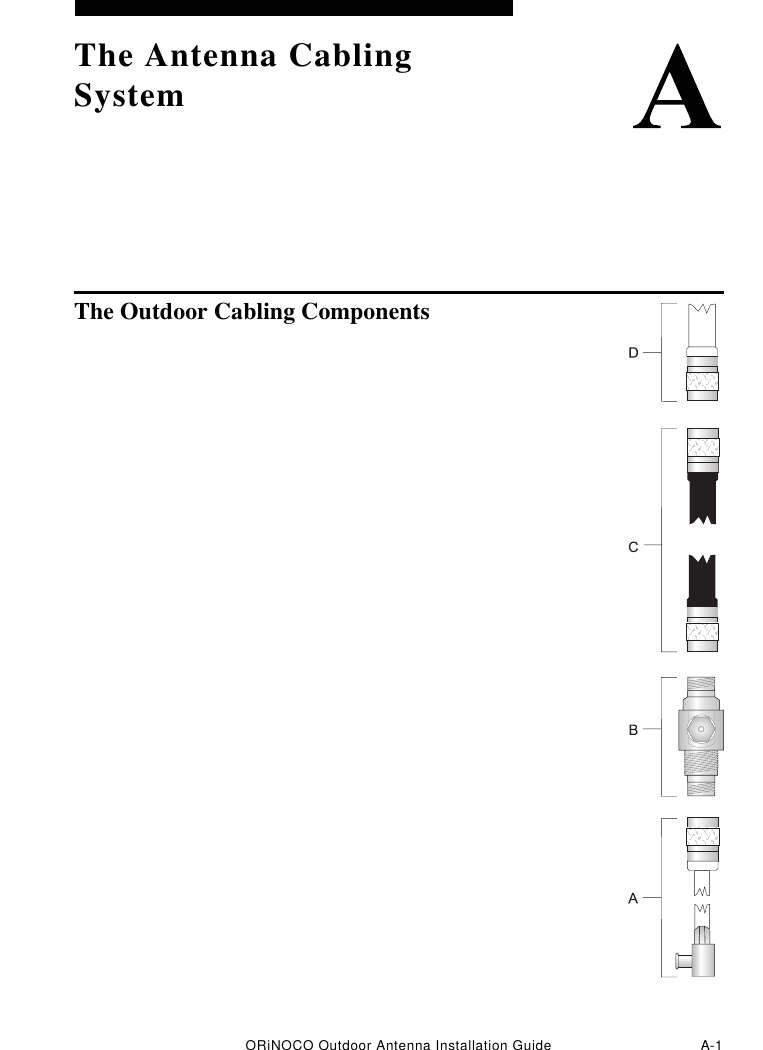
- 2. Antenna overview cable assembly
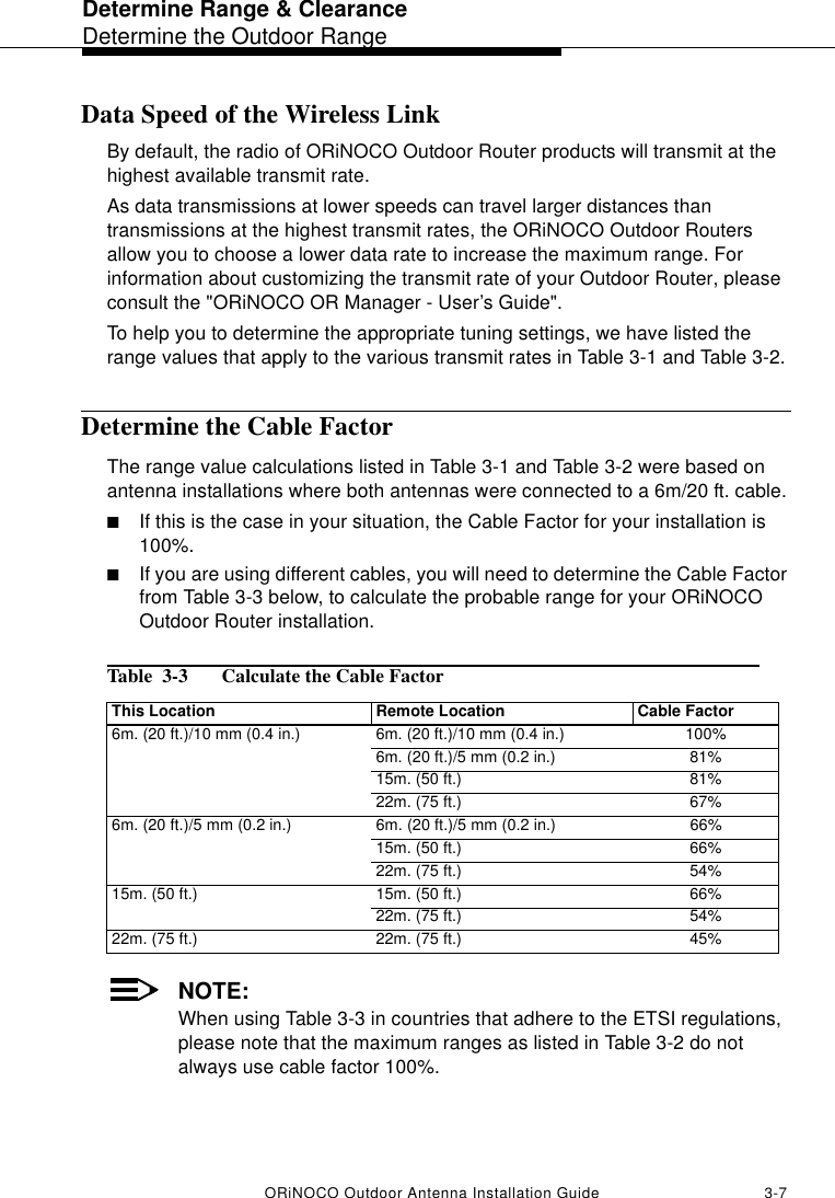
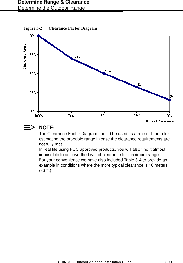
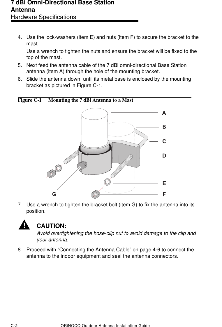
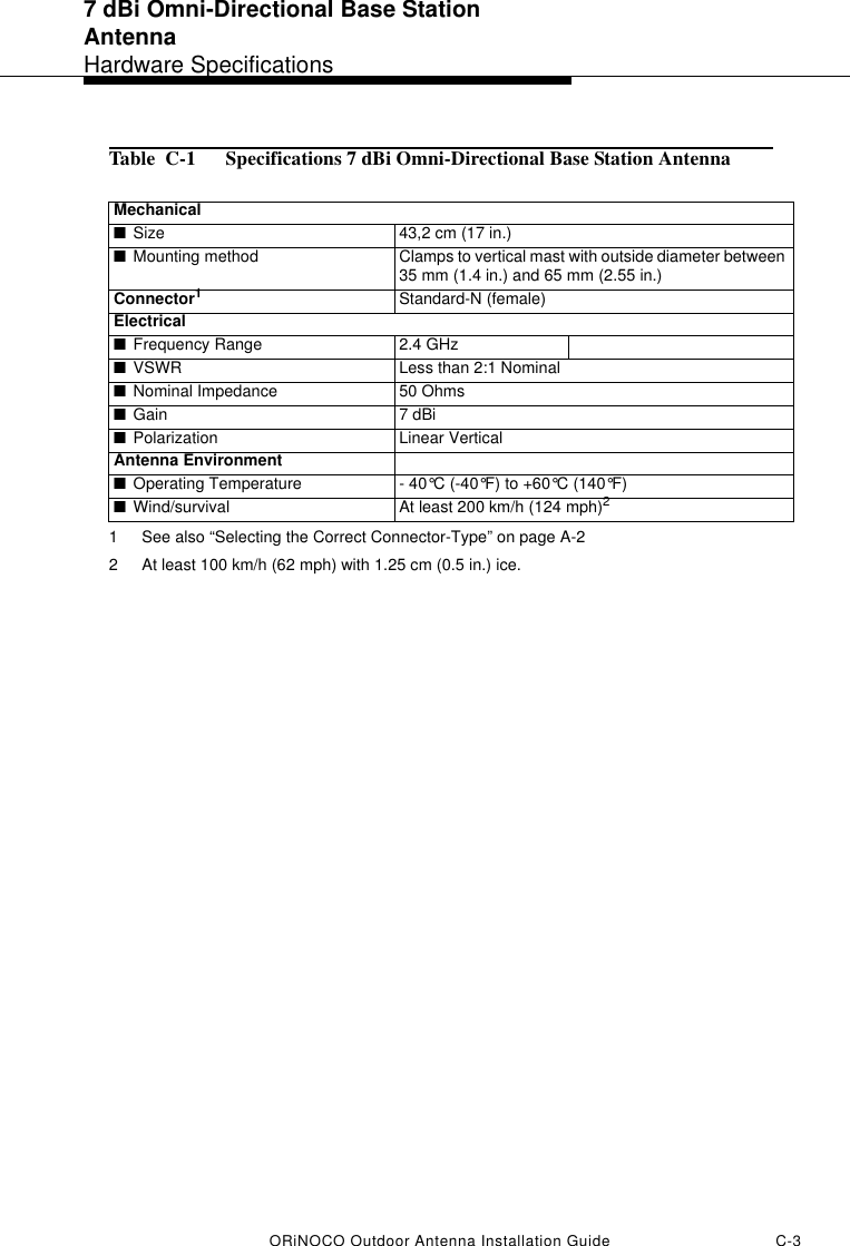
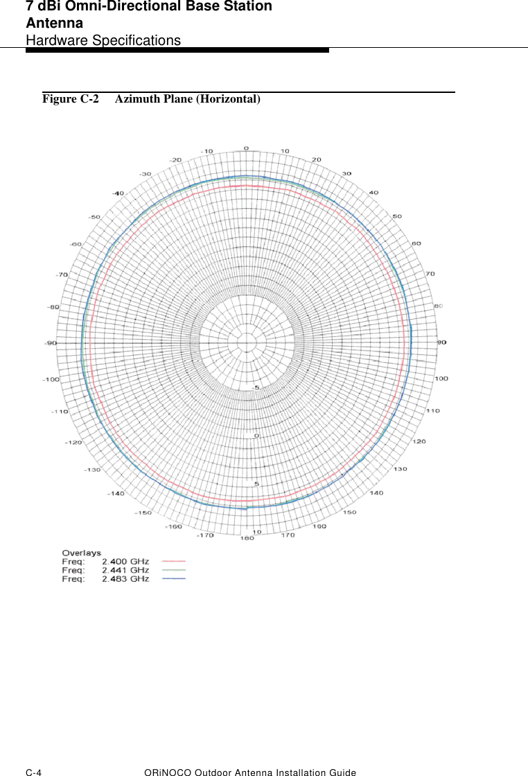
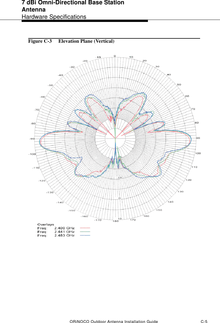
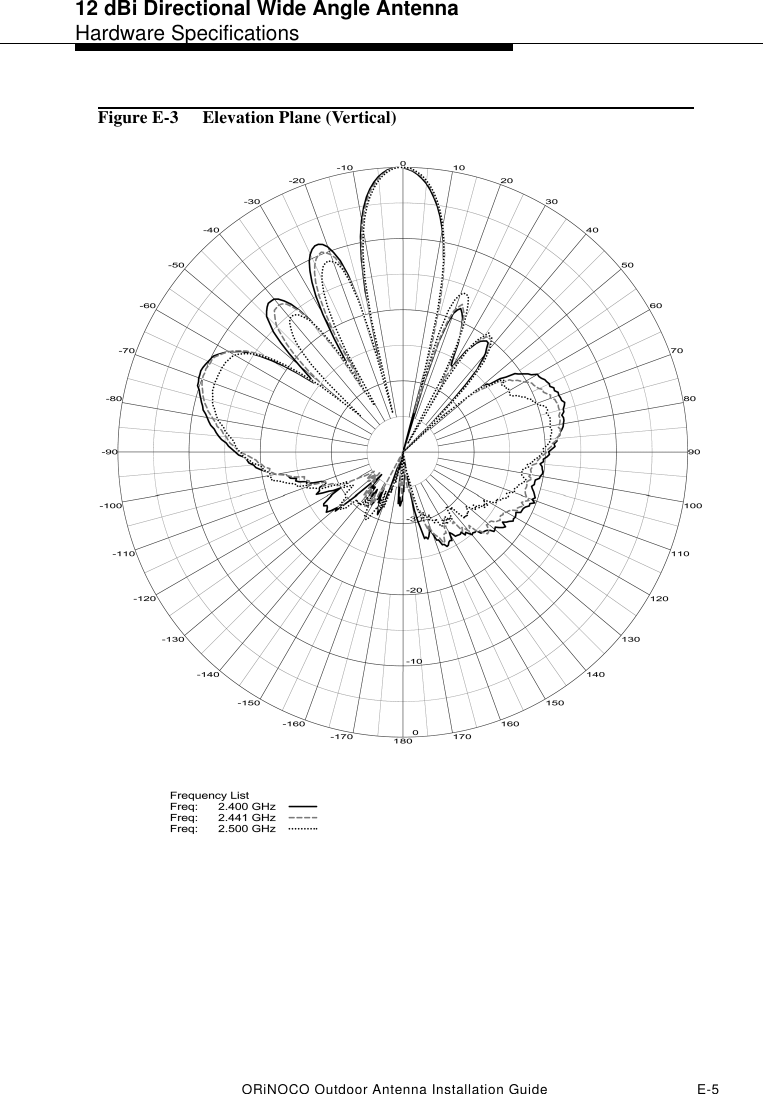
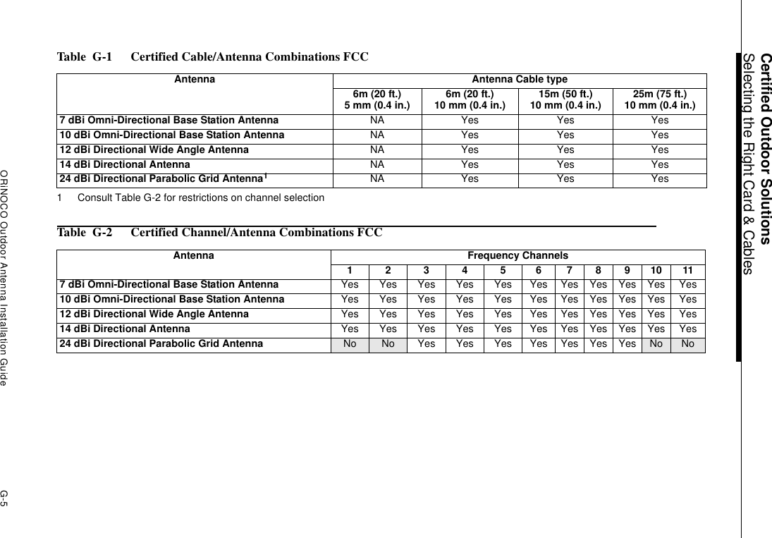
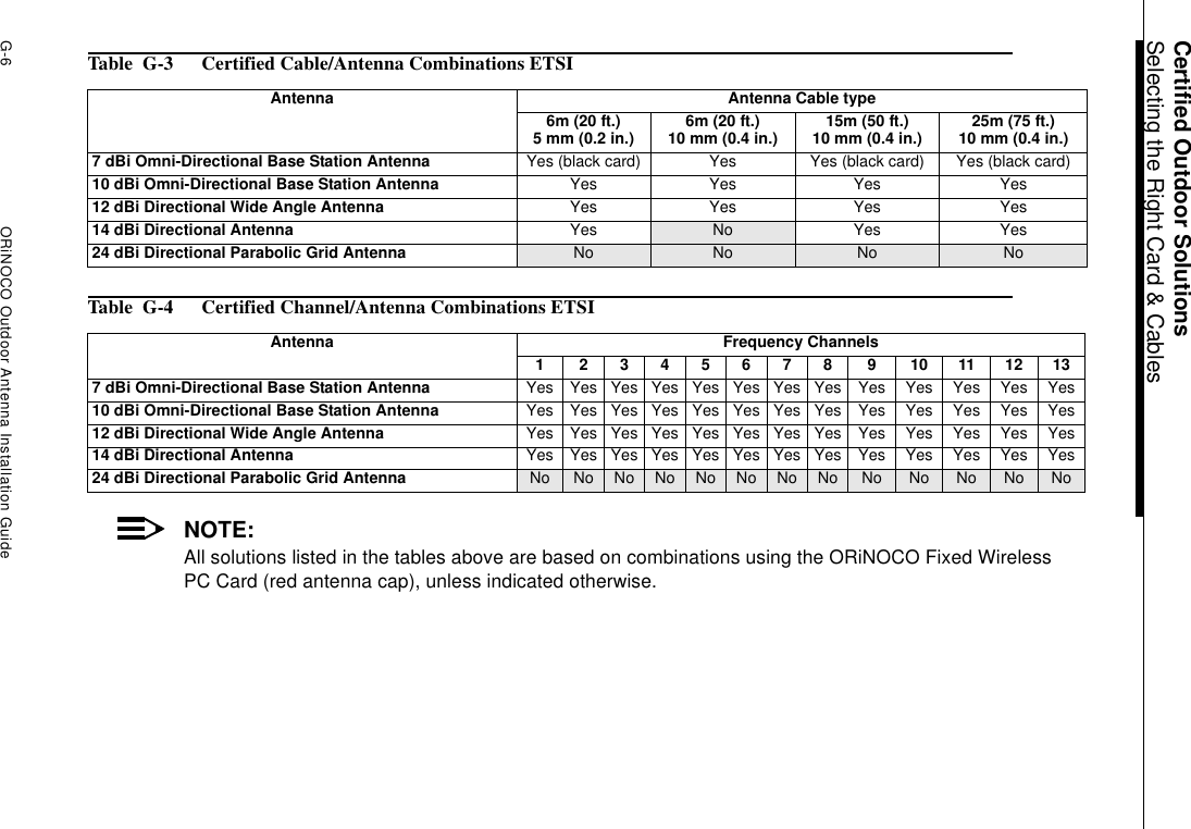
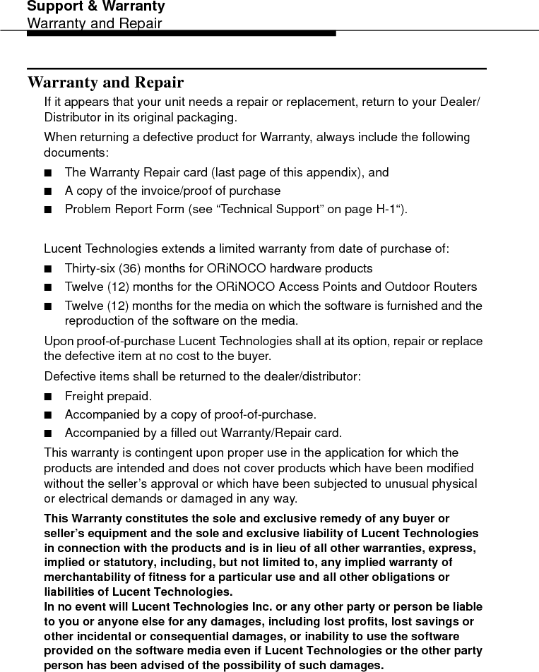
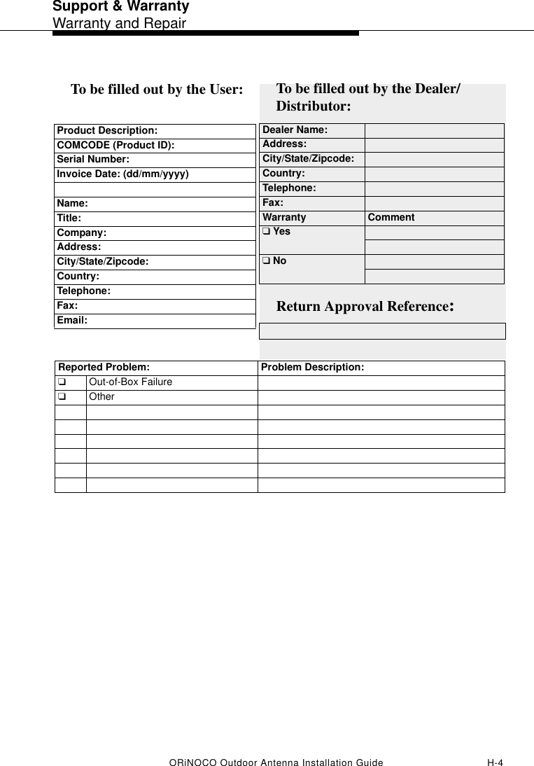
User manual