Agere Systems Nederland WLPCE508A AP-2000 5GHz ORiNOCO CardBus NIC User Manual
Agere Systems Nederland B.V. AP-2000 5GHz ORiNOCO CardBus NIC
User Manual

802.11a PC Card
Quick Installation Guide


Quick Installation Guide
WirelessTM 802.11a PC Card
54 Mbps wireless network card
Other trademarks or brand names mentioned herein are trademarks or registered trademarks of their respec-
tive companies.
AP-2000
E062002-R01

i
Contents
Introduction 1
Package Checklist 1
System Requirements 1
Applications 2
Hardware Description 3
Hardware Installation 3
Driver Installation and Configuration 4
Windows 98/Me/2000/XP Driver Installation 4
Windows 98 Configuration 7
Windows Me/2000/XP Configuration 8
Network Configuration and Planning 15
Network Topologies 15
Ad Hoc Wireless LAN 15
Infrastructure Wireless LAN 16
Infrastructure Wireless LAN for Roaming Wireless PCs 17
Troubleshooting 18
Adapter Installation Problems 18
Network Connection Problems 18
The 802.11a Wireless Products Maximum Distance Table 19
Compliances 20
FCC Class B Certification 20
FCC RF Radiation Exposure Statement 20
CSA Statement (Canada) 20
Specifications 21
Terminology 23

Contents
ii

1
Introduction
The WirelessTM 802.11a PC Card is a 54 Mbps wireless network
card that seamlessly integrates with existing Ethernet networks to support applications
such as mobile users or temporary conferences. This solution offers fast, reliable wireless
connectivity with considerable cost savings over wired LANs (which include long-term
maintenance overhead for cabling). Just plug wireless cards into your notebook PCs and
start networking.
Using this card in conjunction with a WirelessTM WA5001 802.11a Wireless Access Point,
you can create an instant network that allows users on the wireless LAN to access
resources on the wired LAN. Moreover, moving or expanding your network is as easy as
moving or installing additional access points – no wires!
Package Checklist
The WirelessTM PC Card package includes:
•1 Wireless
TM 802.11a PC Card (AP-2000 PC Card)
• 1 Driver and Utility CD-ROM
• This User Guide
Inform your dealer if there are any incorrect, missing, or damaged parts. If possible, retain
the carton, including the original packing materials. Use them again to repack the product
if there is a need to return it for repair.
System Requirements
Before you install the Wireless PC Card, check your system for the following
requirements:
• A computer with a CardBus slot
• Windows 98/Me/2000/XP (Have the Windows installation CD-ROM ready for use
during installation)
• A minimum of 30 Mbytes of free disk space for installing the driver and utility program
Other IEEE 802.11a-compliant devices installed in your service area (such as the
Wireless 802.11a Access Point).

2
Applications
The Wireless products offer a fast, reliable, cost-effective solution for wireless client
access to the network in applications such as:
• Remote access to corporate network information
E-mail, file transfer, and terminal emulation.
•Difficult-to-wire environments
Historical or old buildings, asbestos installations, and open areas where wiring is
difficult to employ.
• Frequently changing environments
Retailers, manufacturers, and banks which frequently rearrange the workplace or
change location.
• Temporary LANs for special projects or peak times
Trade shows, exhibitions, and construction sites which need temporary setup for a
short time period. Retailers, airline and shipping companies which need additional
workstations for a peak period. Auditors who require workgroups at customer sites.
• Access to databases for mobile workers
Doctors, nurses, retailers, or white-collar workers who need access to databases while
being mobile in a hospital, retail store, or an office campus.
• SOHO users
SOHO (Small Office and Home Office) users who need easy and quick installation of a
small computer network.
3
Hardware Description
The Wireless PC Card is fully compliant with 802.11a wireless networking as defined in
IEEE 802.11a. It can be installed in any notebook with a CardBus slot. Support is
provided for Windows 98/Me/2000/XP.
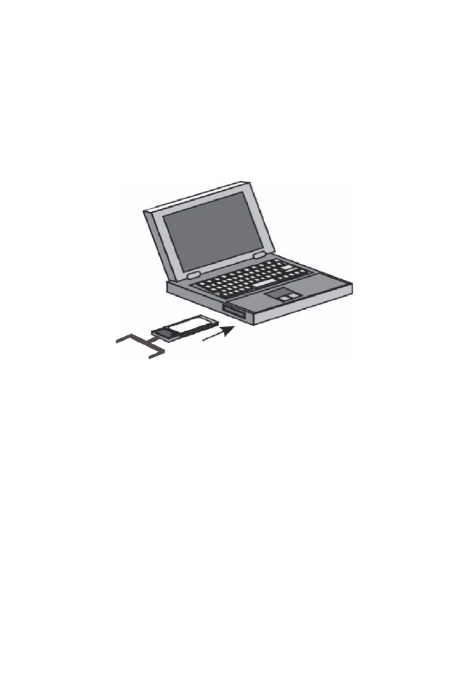
Hardware Installation
1. Turn your computer on and boot to your operating system.
2. With the CardBus adapter 68-pin connector facing the CardBus slot and the label
facing up, slide the card completely into the CardBus slot as shown below.
Note: You may insert or remove the CardBus adapter at any time. It is not necessary to power
off your computer to do so.
4
Driver Installation and Configuration
The driver folder on the Driver/Utility CD-ROM contains the software drivers available for
the WirelessTM 802.11a PC Card.
Windows 98/Me/2000/XP Driver Installation
You may find that these instructions do not exactly match your version of Windows. This
is because these steps and screenshots were created from Windows 2000. Windows 98,
Windows Millennium Edition, and Windows XP are similar, but not identical, to Windows
2000.
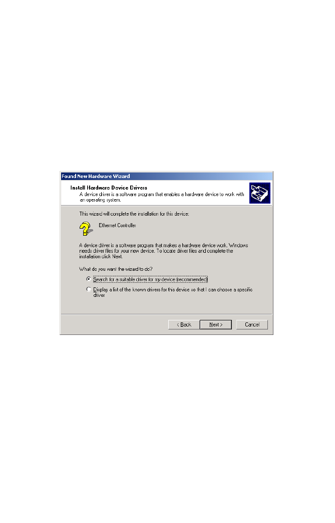
1. Once the card is inserted, Windows 98/Me/2000/XP will automatically detect the new
hardware and prompt you to install the driver. Click “Next.”
Windows 98/Me/2000/XP Driver Installation
5
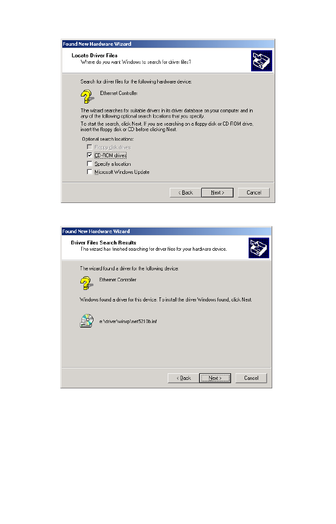
2. Insert the Driver/Utility CD-ROM and click “Next.”
3. Click “Next” to copy files from the CD-ROM.
Driver Installation and Configuration
6
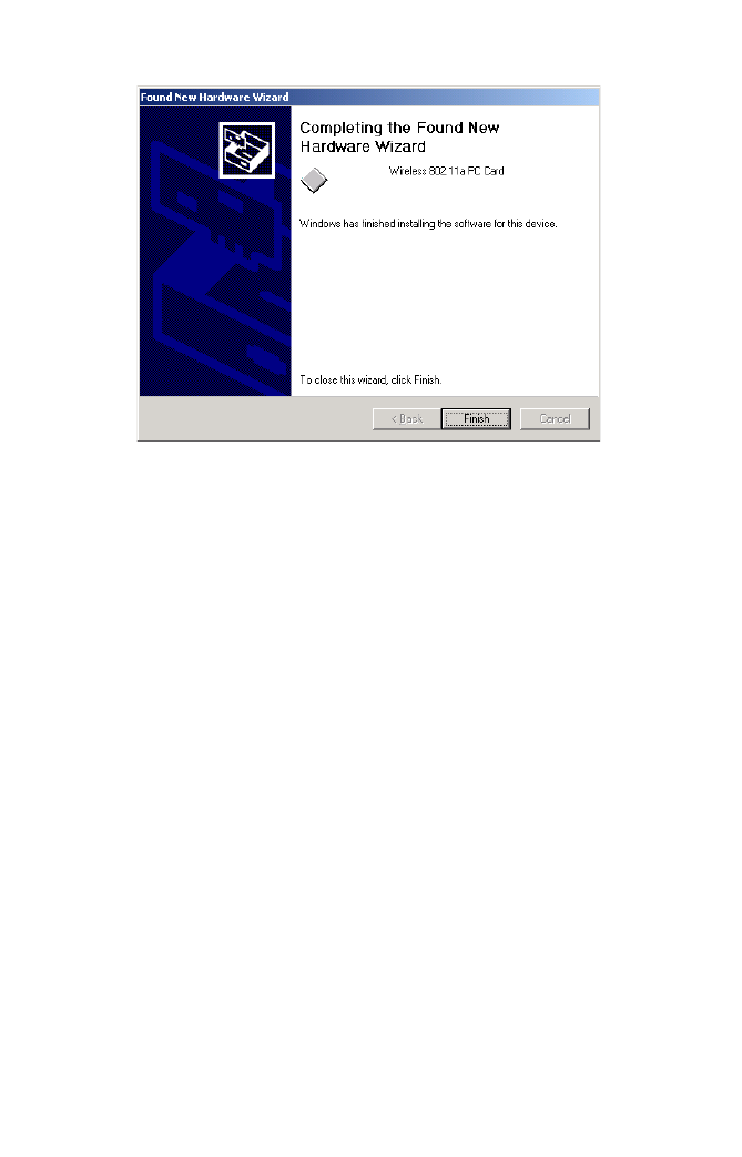
4. Click “Finish” to end the installation.
To communicate with the Wireless 802.11a wireless devices, you may need to
configure the CardBus Adapter. For Windows 98, see “Windows 98 Configuration”
on page 7. For Windows Me/2000/XP see “Windows Me/2000/XP Configuration” on
page 8.
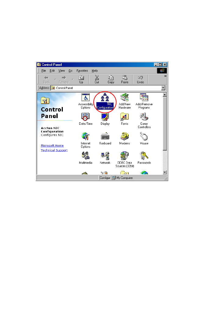
Windows 98 Configuration
7
Windows 98 Configuration
1. From the “Start” menu, select “Settings” then click on “Control Panel.”
2. Double-click on the “NIC Configuration” icon. A configuration dialog box similar to the
one shown in step 5 on page 11 will appear. For the remaining configuration
instructions, go to page 14 and continue from Step 5.
Driver Installation and Configuration
8
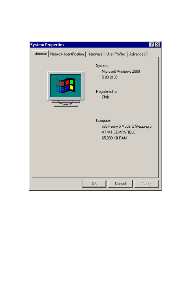
Windows Me/2000/XP Configuration
1. On your desktop, right click “My Computer,” click “Properties” then click the
“Hardware” tab in the “System Properties” dialog box.
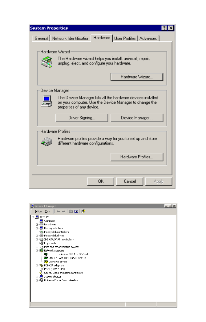
Windows Me/2000/XP Configuration
9
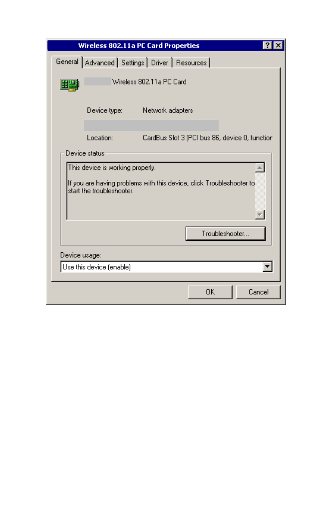
2. Click “Device Manager.”
3. Click “Network adapters” then click “Wireless 802.11a PC Card.”
Driver Installation and Configuration
10
4. Click the “Settings” tab.
Windows Me/2000/XP Configuration
11
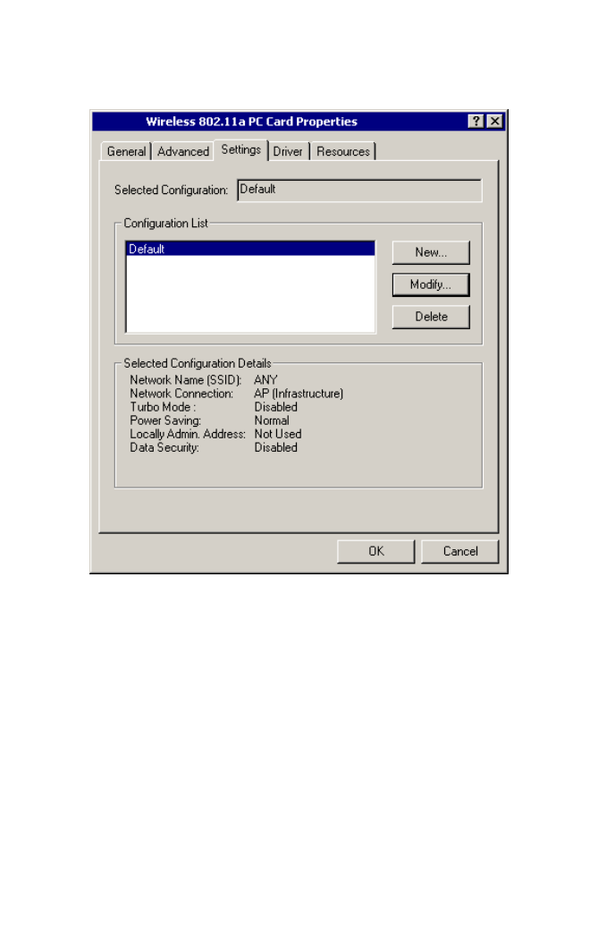
5. You may either modify the default settings or create a new configuration profile. To
modify the default settings, click “Modify.” To create a new configuration profile, click
“New.”
Driver Installation and Configuration
12
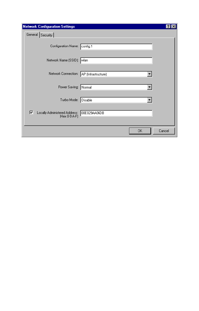
6. The “Network Configuration Settings” dialog box will open.
Configuration Name – Enter the configuration name.
Network Name (SSID) – Set the “SSID” (Service Set ID) to the same as that used by
the ad hoc workgroup or access point you want to connect to (the Access Point
default is “ANY”).
Note: The SSID is case sensitive and can consist of up to 32 alphanumeric characters.
Network Connection – Set “Network Connection” to “Ad Hoc” or
“AP (Infrastructure)” depending on the type of network you want to connect to
(see page 15).
Power Saving – Enable the “Power Saving” mode to reduce power loading (the
default is “Normal”).
Locally Administered Address – Check this box if you wish to set your own MAC
address for the Cardbus Adapter. A MAC address consists of 6 hexadecimal
numbers.
7. Click “OK” when you have finished the configuration profile. This returns you to the
card properties dialog box (see step 5 on page 11). The profile can be modified by
selecting the profile name from the “Configuration List” and clicking on “Modify.”
Windows Me/2000/XP Configuration
13
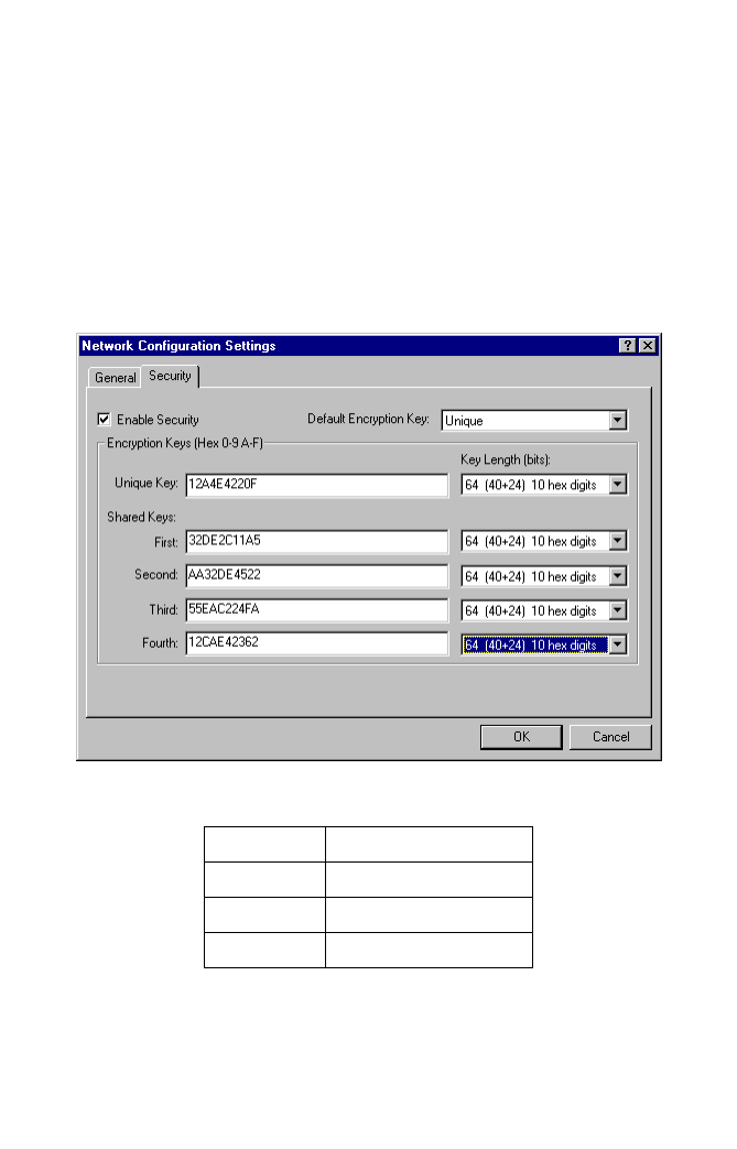
8. Wired Equivalent Privacy (WEP) is implemented in this device to prevent
unauthorized access to your wireless network and provide more secure wireless data
transmission. The CardBus supports “Shared Key” encryption with key lengths from
standard 64-bit, industry standard 128-bit, to extended 152-bit. In addition to the
standard WEP key, a per-station unique key is also supported. All wireless devices
must have the same Key ID values to communicate.
To enter security keys click the “Security” tab in the “Network Configuration Settings”
dialog box and check “Enable Security.” Select 64, 128, or 152-bit entry from the
drop-down list then enter the required number of hexadecimal digits for the unique
key and the first to fourth shared keys. Click “OK.” This will return you to the card
properties dialog box (see step 5 on page 11).
Key Length Hex Digits per Key ID
64-Bit 10
128-Bit 26
152-Bit 32
Driver Installation and Configuration
14
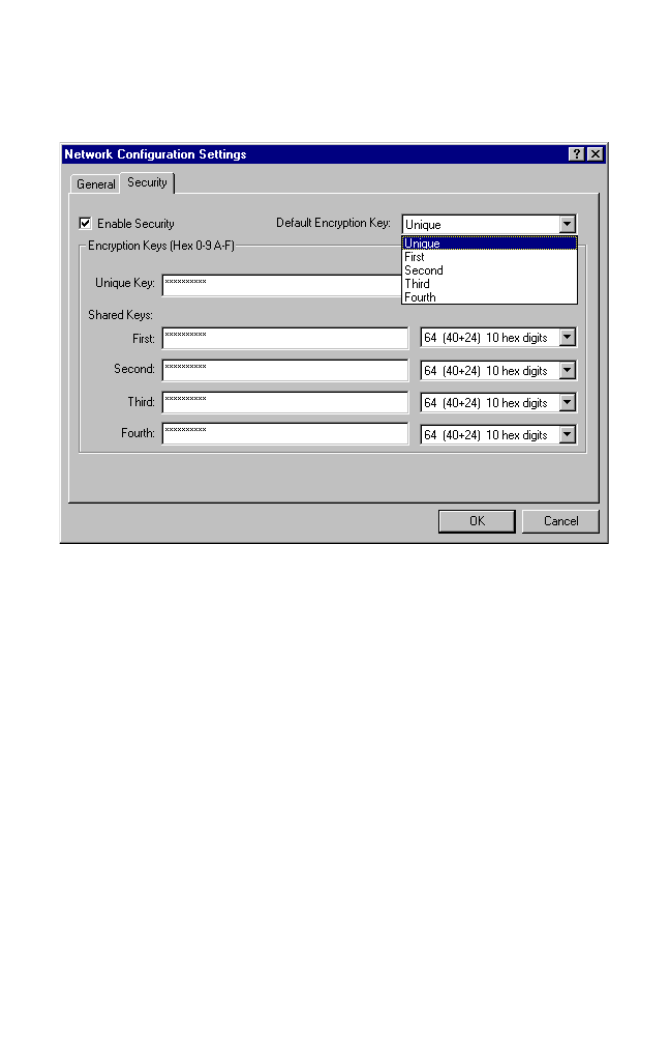
9. Click “Modify” in the card properties dialog box (see step 5 on page 11), click the
“Security” tab in the “Network Configuration Settings” dialog box, then select
“Unique” or one of the shared keys from the drop-down list. Click “OK.” This will
return you to the card properties dialog box (see step 5 on page 11).
10. Click “OK” in the card properties dialog box (see step 5 on page 11).
11. Click “Yes” in the control panel dialog box to restart your computer and implement
your new settings.
12. To add protocols after installation, go to “Control Panel” and double-click “Network.”
13. Click “Add” to install the network protocols you want to use, such as IPX/SPX,
NetBEUI or TCP/IP. If you install TCP/IP, be sure to set the appropriate Gateway,
DNS Server, and Domain for your network. If you install an IPX/SPX-compatible
protocol, then you also need to install the Client for NetWare Networks.
14. Click “File and Print Sharing” to share files or printers.
15. Click “Close” in the Network dialogue box and the system will restart your computer.
Network Topologies
15
Network Configuration and Planning
The wireless solution supports a stand-alone wireless network configuration, as well as
an integrated wireless and 10/100 Mbps wired LAN configuration.
The AP-2000 PC Card can be configured as:
• Ad hoc – for small groups that only communicate with each other
• Infrastructure – for enterprise LANs
Network Topologies
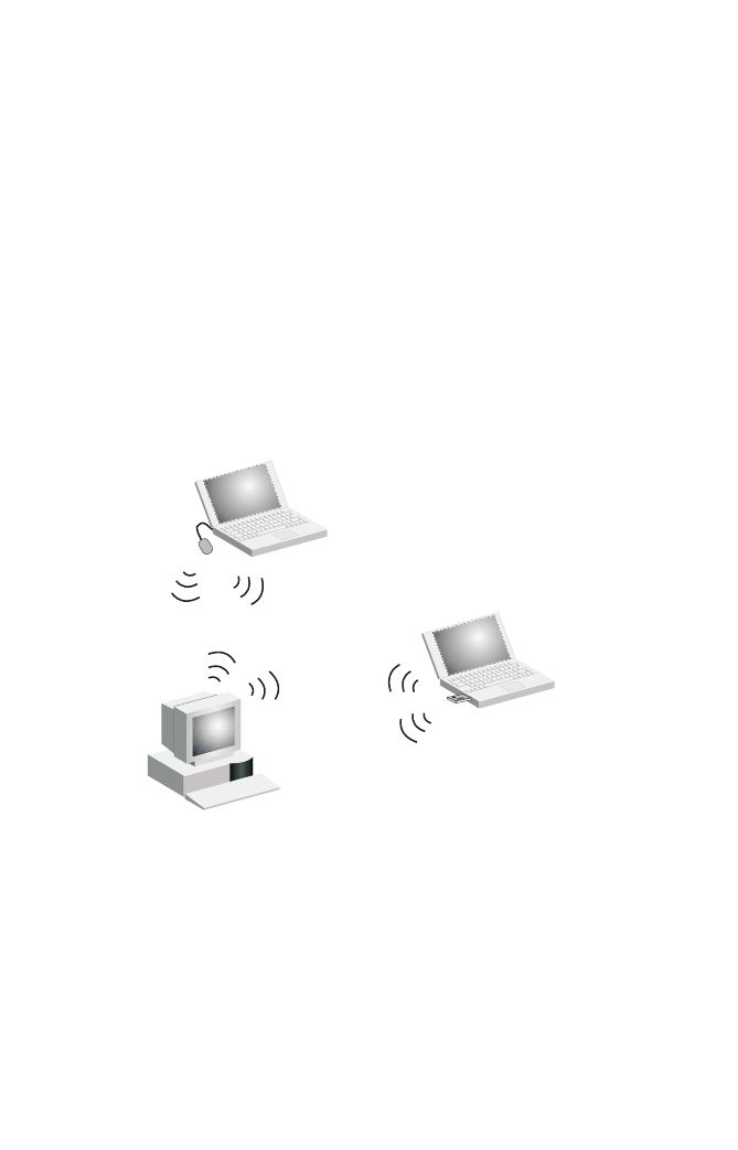
Ad Hoc Wireless LAN
An ad hoc wireless LAN consists of a group of computers, each equipped with a wireless
adapter, connected via radio signals as an independent wireless LAN. Computers in a
specific ad hoc wireless LAN must be configured to the same radio channel.
An ad hoc wireless LAN can be used in a SOHO or temporary environment.
Ad Hoc Wireless LAN
Notebook with
Wireless USB Adapter
Notebook with
Wireless PC Card
PC with Wireless
PCI Adapter
Network Configuration and Planning
16
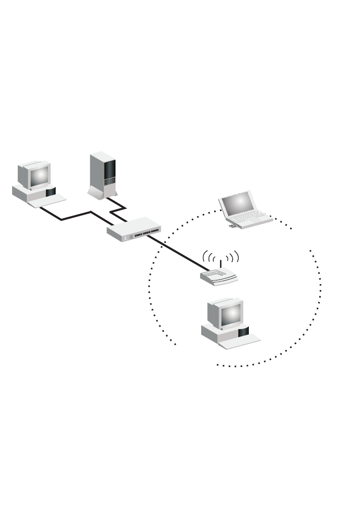
Infrastructure Wireless LAN
The AP-2000 PC Card can also provide access to a wired LAN for wireless clients. An
integrated wired/wireless LAN is called an infrastructure configuration. A Basic Service
Set (BSS) consists of a group of wireless PCs, and an access point that is directly
connected to the wired LAN. Each wireless PC in this BSS can talk to any computer in its
wireless group via a radio link, or access other computers or network resources in the
wired LAN infrastructure via the access point.
The infrastructure configuration not only extends the accessibility of wireless PCs to the
wired LAN, but also increases the effective wireless transmission range for wireless PCs
by passing their signal through one or more access points.
A wireless infrastructure can be used for access to a central database, or for connecting
mobile workers, as shown in the following figure.
File
Server
Switch
Desktop PC
Access Point <BSS2>
Notebook with Wireless
PC Card Adapter
Seamless Roaming
<ESS>
Switch
Access Point
<BSS1>
PC with Wireless
PC I Adapter
Notebook with Wireless
PC Card Adapter
Network Topologies
17
Infrastructure Wireless LAN for Roaming Wireless PCs
The Basic Service Set (BSS) is the communications domain for each Wireless Access
Point. For wireless PCs that do not need to support roaming, set the domain identifier
(SSID) for the wireless card to the SSID of the access point to which you want to connect.
Check with your administrator for the SSID of the access point to which he wants you to
connect.
A wireless infrastructure can also support roaming for mobile workers. More than one
access point can be configured to create an Extended Service Set (ESS). By placing the
access points so that a continuous coverage area is created, wireless users within this
ESS can roam freely. All wireless network cards, adapters, and wireless access points
within a specific ESS must be configured with the same SSID.
File
Server
Switch
Desktop PC
Access Point
Wired LAN Extension
to Wireless Adapters
PC with Wireless
PCI Adapter
Notebook with Wireless
PC Card Adapter

18
Troubleshooting
Adapter Installation Problems
If your computer cannot find the Wireless CardBus Adapter or the network driver does not
install correctly, check the following:
• Make sure the adapter is securely seated in the CardBus slot. Check for any hardware
problems, such as physical damage to the card’s connector.
• Try the card in another CardBus slot. If this also fails, test your computer with another
AP-2000 PC Card wireless card that is known to operate correctly.
• Make sure your computer is using the latest BIOS.
• If there are other network adapters in the computer, they may be causing conflict.
Remove all other adapters from the computer and test the wireless adapter separately.
• Check for a defective computer or CardBus slot by trying the adapter in another
computer that is known to operate correctly.
Network Connection Problems
If your wireless station cannot communicate with a computer in the Ethernet LAN when
configured for infrastructure mode, check the following:
• Make sure the access point that the station is associated with is powered on.
• Make sure your wireless station is configured with the same operating radio channel as
the access point.
• If you still cannot connect, change the access point and all the stations within the BSS
to another radio channel.
• Make sure the CardBus adapter’s SSID is the same as that of the access point.

The 802.11a Wireless Products Maximum Distance Table
19
The 802.11a Wireless Products Maximum Distance Table
Important Notice
Maximum distances posted below are actual tested distance thresholds. However, there
are many variables such as barrier composition and construction, as well as local
environmental interference, that may impact actual distances and cause you to
experience distance thresholds far lower than those posted below.
Notes: 1. Outdoor Environment: A line-of-sight environment with no interference or
obstruction between access point and users.
2. Indoor Environment: A typical office or home environment with floor to
ceiling obstructions between access point and users.
802.11a Wireless Products Maximum Distance Table
Speed and Distance Ranges
Environmental
Condition
72 Mbps 54 Mbps 48 Mbps 36 Mbps 24 Mbps 18 Mbps 12 Mbps 9 Mbps 6 Mbps
Outdoor
Environment1
35 m
(115 ft)
40 m
(132 ft)
220 m
(726 ft)
250 m
(825 ft)
320 m
(1056 ft)
350 m
(1155 ft)
380 m
(1254 ft)
450 m
(1485 ft)
500 m
(1650 ft)
Indoor
Environment2
12 m
(40 ft)
18 m
(60 ft)
25 m
(82 ft)
30 m
(99 ft)
35 m
(115 ft)
40 m
(132 ft)
45 m
(149 ft)
45 m
(149 ft)
50 m
(165 ft)
Compliances
FCC Class B Certification
FCC ID: IMRWLPCE508A
This device complies with Part 15 of the FCC Rules Operation is subject to the following
conditions:
1. This device may not cause harmful interference.
2. This device must accept any interference received, including interference that may
cause undesired operation
Warning: This equipment has been tested and found to comply with the limits for a Class
B digital device, pursuant to Part 15 of the FCC Rules. These limits are designed to
provide reasonable protection against harmful interference in a residential installation.
This equipment generates, uses and can radiate radio frequency energy and, if not
installed and used in accordance with the instructions, may cause harmful interference to
radio communication. However, there is no guarantee that interference will not occur in a
particular installation. If this equipment does cause harmful interference to radio or
television reception, which can be determined by turning the equipment off and on, the
user is encouraged to try to correct the interference by one or more of the following
measures:
Reorient or relocate the receiving antenna.
Increase the distance between the equipment and Receiver.
Connect the equipment into an outlet on a circuit different from the one which the
Receiver is connected to.
Consult the dealer or an experienced radio/TV technician for help.
Notice: The changes or modifications not expressly approved by the party responsible for
compliance could void your authority to operate the equipment.
FCC RF Radiation Exposure Statement
This equipment complies with FCC RF radiation exposure limits set forth for an
uncontrolled environment. This equipment should be installed and operated with a
minimum distance of 20 centimeters between the radiator and your body.
CSA Statement (Canada)
3857104650A
This digital apparatus does not exceed the Class B limits for radio noise emissions from
digital apparatus set out in the Radio interference Regulations of Industry Canada.
Le présent appareil numerique n’émet pas de bruits radio-électriques dépassant less
limites applicables aux apparails numériques de la classe B prescrites dans le Réglement
sur le brouillage radioélectrique édicté par I’Industrie.
Notice: Radio Frequency Interference Requirements: The device is restricted to
indoor use only. FCC requires this product to be used indoor due to its operation in
the frequency range 5.15 to 5.25GHz.

21
Specifications
Functional Criteria
Data Rate Normal Mode: 6, 9, 12, 18, 24, 36, 48, 54 Mbps
Standards Conformance IEEE 802.11a
Operating Range Up to 500 m (1650 ft)
Radio Signal
Signal Type Orthogonal Frequency Division Multiplexing (OFDM)
Operating Frequency 5.15 ~ 5.25 GHz (lower band) for US/Canada, Japan
5.25 ~ 5.35 GHz (middle band) for US/Canada
Sensitivity
Modulation
Modulation/Rates Sensitivity (dBm)
BPSK (6 Mbps) -85
BPSK (9 Mbps) -84
QPSK (12 Mbps) -83
QPSK (18 Mbps) -81
16 QAM (24 Mbps) -78
16 QAM (36 Mbps) -74
64 QAM (48 Mbps) -69
64QAM (54 Mbps) -65
Modulation 5.15-5.25 GHz (dBm) 5.25-5.35 GHz (dBm)
BPSK (6 Mbps) 14 16.5
BPSK (9 Mbps) 14 16.5
QPSK (12 Mbps) 14 16.5
QPSK (18 Mbps) 14 16.5
16 QAM (24 Mbps) 14 16.5

Specifications
22
Physical Characteristics
Input Voltage 3.3 V
Power Consumption
Idle/Listening 1478 mW, Power Save Mode 40 mW
Base Mode: TX 1657 mW, RX 1247 mW,
Idle/Listening 1238 mW, Power Save Mode 40 mW
Weight 50 g (4.8 oz)
Dimensions 11.5 x 5.3 cm (4.53 x 2.09 in)
Antenna Built-in side-stem antenna
LED Indicators Power, Network
Host Interface 68-pin connector to CardBus slot
Environmental
Temperature 0 to 50 °C / 32 to 140 °F (operating)
0 to 70 °C / 32 to 158 °F (storage)
Humidity 5 to 80% (non-condensing)
Emissions FCC Class B
Antenna Built-in side-stem antenna
LED Indicators Power, Network
Safety CSA/NTRL (CSA 22.2 No. 950 & UL 1950)
Vibration/Shock/Drop: IEC 68-2-34/IEC 68-2-32
Standards 802.11a
Software Drivers
NDIS Drivers Windows 98
Windows Me
Windows 2000
Windows XP
16 QAM (36 Mbps) 14 16.5
64 QAM (48 Mbps) 11 11
64 QAM (54 Mbps) 7 7
Modulation 5.15-5.25 GHz (dBm) 5.25-5.35 GHz (dBm)

23
Terminology
The following is a list of terminology used in this document.
Access Point – An internetworking device that seamlessly connects wired and wireless
networks.
Ad hoc – An ad hoc wireless LAN is a group of computers each with LAN adapters,
connected as an independent wireless LAN.
Backbone – The core infrastructure of a network. The portion of the network that
transports information from one central location to another central location where it is
unloaded onto a local system.
Base Station – In mobile telecommunications, a base station is the central radio
transmitter/receiver that maintains communications with the mobile radiotelephone sets
within its range. In cellular and personal communications applications, each cell or
micro-cell has its own base station; each base station in turn is interconnected with other
cells’ bases.
BSS – BSS stands for “Basic Service Set.” It is an access point and all the LAN PCs that
are associated with it.
CSMA/CA – Carrier Sense Multiple Access with Collision Avoidance.
ESS – ESS (ESS-ID, SSID) stands for “Extended Service Set.” More than one BSS is
configured to become an Extended Service Set. LAN mobile users can roam between
different BSSs in an ESS (ESS-ID, SSID).
Ethernet – A popular local area data communications network, which accepts
transmission from computers and terminals. Ethernet operates on a 10 Mbps baseband
transmission rate, using a shielded coaxial cable, or shielded twisted pair telephone wire.
Infrastructure – An integrated wireless and wired LAN is called an infrastructure
configuration.
Roaming – A wireless LAN mobile user moves around an ESS and maintains a
continuous connection to the infrastructure network.
RTS Threshold – Transmitters contending for the medium may not be aware of each
other. RTS/CTS mechanism can solve this “Hidden Node Problem.” If the packet size is
smaller than the preset RTS Threshold size, the RTS/CTS mechanism will NOT be
enabled.
WEP – “Wired Equivalent Privacy” is based on the use of 64-bit, 128-bit, or 152-bit keys
and the popular RC4 encryption algorithm. Wireless devices without a valid WEP key will
be excluded from network traffic.

24
This device complies with Part 15 of FCC Rules.
Operation is subject to the following two conditions:
(1) This device may not cause harmful interference and
(2) This device must accept any interference received,
including interference that may cause undesired operation.
Notice: The changes or modifications not expreslly approved by the
party responsible for compliance could void the user's authority to
operate the equipment.