Agfa NV 5367 Drystar Axys/xxx Tabletop Printer User Manual Drystar AXYS
Agfa Gevaert N V Drystar Axys/xxx Tabletop Printer Drystar AXYS
Agfa NV >
Contents
- 1. user manual 1
- 2. user manual 2
- 3. user manual 3
user manual 3
109
2852 A EN 20070205
DRYSTAR AXYS
3Do one of the following:
•Press the Confirm key (YES) to start the QC procedure and proceed with step 4.
•Press the Escape key (NO) to quit.
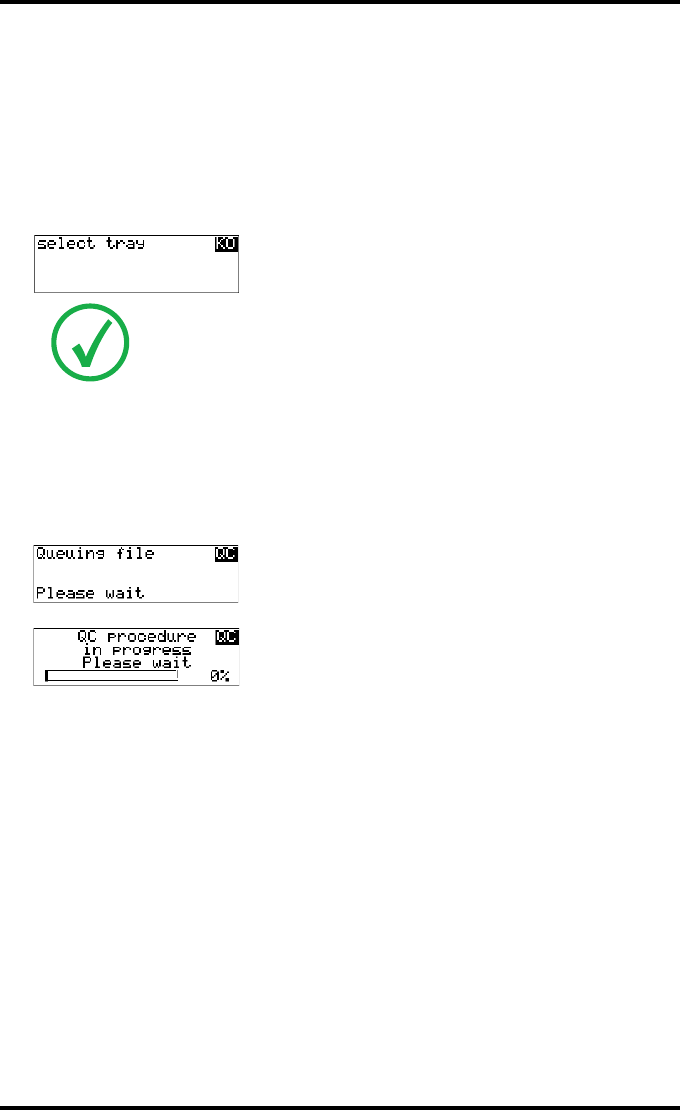
4Define the tray for printing.
The ‘Select tray’ screen appears:
5Press the Up/Down arrow keys to select the desired tray, followed by the Con-
firm key.
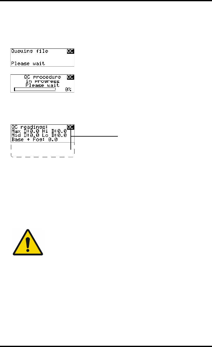
The following screens appear successively:
The Drystar AXYS will automatically print the QC mammography test image.
Note: When controlling the Drystar AXYS via a remote PC, The ‘Select input
tray’ screen is preceded by a screen, which allows you to:
Note: Start the quality control procedure immediately,
Note: Edit additional data for the last quality control measuring.
1.Upper tray
2.Lower tray
110 2852 A EN 20070205
DRYSTAR AXYS
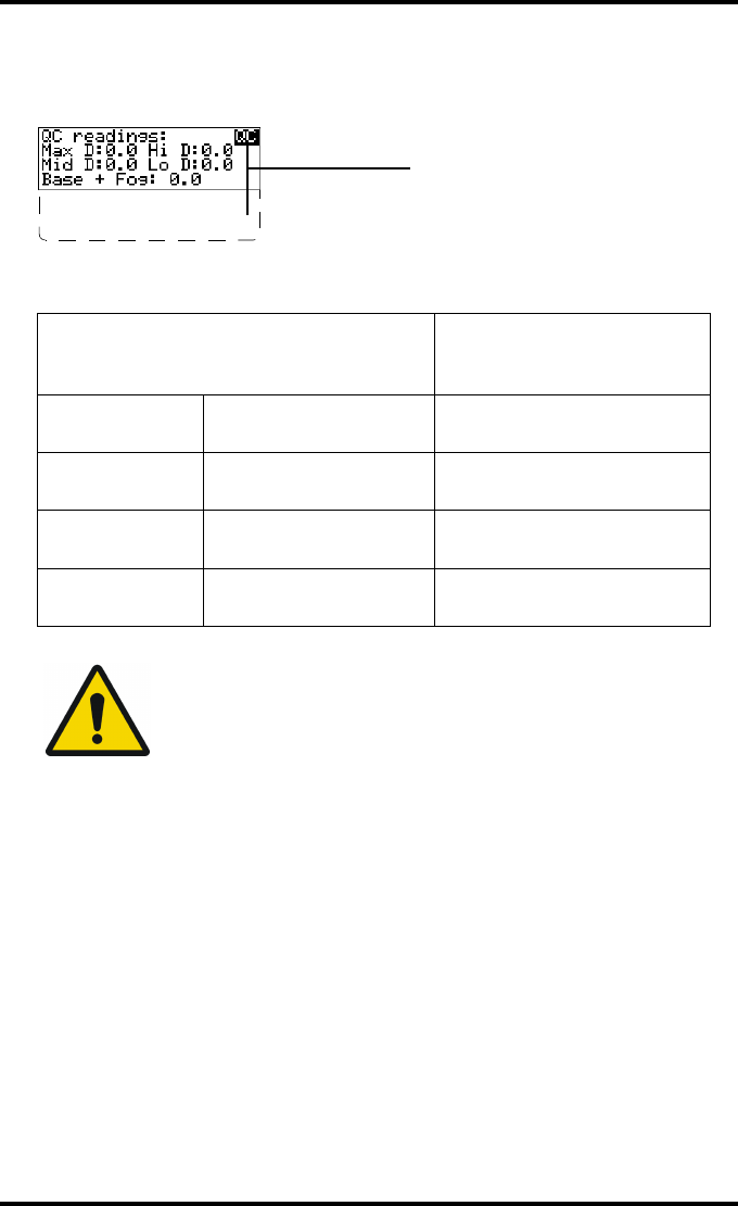
6After the image is printed, the system will display all measured optical density
values:
The displayed values (that have to be monitored) represent the following steps on the
test film:
7Record the density levels on Chart 1 (‘DrystarAXYS Determination of Operating
Levels’). Refer to “Charts for mammography QC (optional)” on page 155.
8Press the Confirm key to return to the main menu.
9Repeat steps 1 through 8 once a day for five consecutive days, as indicated on
the Drystar AXYS Chart 1.
10 Calculate the average value of the densities from the five images. These values
represent operating levels or aim values, for each density.
Operating Level
Value (Macbeth units)
(according to NEMA
standards XR 23-2006)
Base + Fog the density value of the
Base + Fog step 0. 22 ± 0.03
Low density the density value of the
low density step 0.45 ± 0.07
Mid density the density value of the
mid density step 1.20 ± 0.15
High density the density value of the
high density step 2.20 ± 0.15
WARNING: If the mid density value does not meet or exceeds the
recommended values, the cause must be found and the problem
solved before any further clinical films can be printed.
WARNING: Refer to “Preventive maintenance schedule” on
page 121 and “Maintaining image quality and resolving image
quality problems” on page 258 (Reference manual), or call your
local Agfa service organization.
DD: 1.56
(Densitometer=MB924)
The density levels are displayed, e.g:
Max D: x.x Hi D: 2.23
Mid D: 1.13 Lo D: 0.4
Base+Fog: 0.20
DD: x.xx

111
2852 A EN 20070205
DRYSTAR AXYS
11 Record the respective aim (average) values as the ‘Operating levels’ on Charts
2A and 2B (‘Drystar AXYS Daily Density Control Chart’). Refer to “Charts for
mammography QC (optional)” on page 155.
The calculated ‘Operating levels’ should be as follows:
12 These charts will be used for the daily quality test. For more information, refer
to “Performing the daily QC test for mammography application (DT 2 Mammo)
(optional)” on page 116.
Operating Level Value (Macbeth units)
(according to NEMA standards XR 23-2006)
Base + Fog 0. 22 ± 0.03
Low density 0.45 ± 0.07
Mid density 1.20 ± 0.15
High density 2.20 ± 0.15
112 2852 A EN 20070205
DRYSTAR AXYS
Establishing the image geometry reference values
for mammography application (DT 2 Mammo)
(optional)
Procedure
1Print the QC mammography test image or use the previously printed test image.
For an example, see “QC test image for mammography applications (DT 2 Mammo)
(optional)” on page 107.
2To determine the reference values for geometry, measure the distances A and B
of the geometric square on the test image.
3Record these values as reference dimensions Aref and Bref on Chart 4
(‘Drystar AXYS Geometric Consistency Control Chart’). Refer to “Charts for
mammography QC (optional)” on page 155.
These charts will be used for the annual quality test. For more information, refer to
“Performing the Annual QC tests for mammography application (DT 2 Mammo)
(optional)” on page 120.
4Save this film for future reference.
WARNING: Make sure to measure distance A from the left edge of
the left line to the right edge of the right line and distance B from
the upper edge of the upper line to the lower edge of the lower
line.
WARNING: We strongly recommend using a 30 cm (12-inch)
machinist scale with 0.5 mm divisions (1/64 inch).

113
2852 A EN 20070205
DRYSTAR AXYS
Verifying Acceptable Spatial Resolution and
Artifact Levels and Low Contrast Visibility for
mammography application (DT 2 Mammo)
(optional)
Procedure
1Print the QC mammography test image or use the previously printed QC mam-
mography test image used to establish the daily operating density levels.
2Visually check the QC test image for artifacts: no significant disturbing artifacts
should be visible.
3Check the spatial resolution in each of the three ovals. Within each oval there
are three groups, each having five dots. All five dots of each group must be visi-
ble with a magnifying glass. The smallest cluster of 5 dots is only visible if the
viewing conditions are good.
4Check the Low Contrast Visibility at both the high (100 / 95%) and low end
(0 / 5%) of the density scale. You should be able to see the circle in the square
(refer to item 1 on the “QC test image for mammography applications
(DT 2 Mammo) (optional)” on page 107) and the upper circle (refer to item 2
on the “QC test image for mammography applications (DT 2 Mammo)
(optional)” on page 107.
5Record these values at the top of Chart 3 (‘Drystar AXYS Artifacts and Spatial
Resolution Control Chart’).Refer to “Charts for mammography QC (optional)”
on page 155.
WARNING: Good viewing conditions are important for the correct
interpretation of both diagnostic and test images. Make sure that
the light box intensity (luminance) is between 3000 and 6000 cd/
m² (4500 and 6500 °K) for mammography. Use a magnifying glass
and use shutters to collimate. Make sure the ambient light is low.

114 2852 A EN 20070205
DRYSTAR AXYS
6These charts will be used for the weekly quality test. For more information,
refer to “Performing the Weekly QC tests for mammography application
(DT 2 Mammo) (optional)” on page 118.
WARNING: In case of significant artifacts or insufficient spatial
resolution, the cause must be found and the problem solved
before any further clinical films can be printed.
WARNING: Refer to “Preventive maintenance schedule” on
page 121 and “Maintaining image quality and resolving image
quality problems” on page 258 (Reference manual), or call your
local Agfa service organization.

115
2852 A EN 20070205
DRYSTAR AXYS
Performing quality control (QC) tests
for mammography application
(DT 2 Mammo) (optional)
The following procedures must be performed daily, weekly or annually as indi-
cated.
The reason for performing quality control tests is to determine if any significant
image quality variation or deterioration has occurred which may require correc-
tive action. Comparing the results of the tests with the reference values previ-
ously established does this.
This procedure allows the operator to take the necessary preventive actions
before any image quality loss can take place.
116 2852 A EN 20070205
DRYSTAR AXYS
Performing the daily QC test for mammography
application (DT 2 Mammo) (optional)
Procedure
1Turn on the Drystar AXYS and wait at least for 15 minutes. Refer to “Switching
on the Drystar AXYS” on page 48.
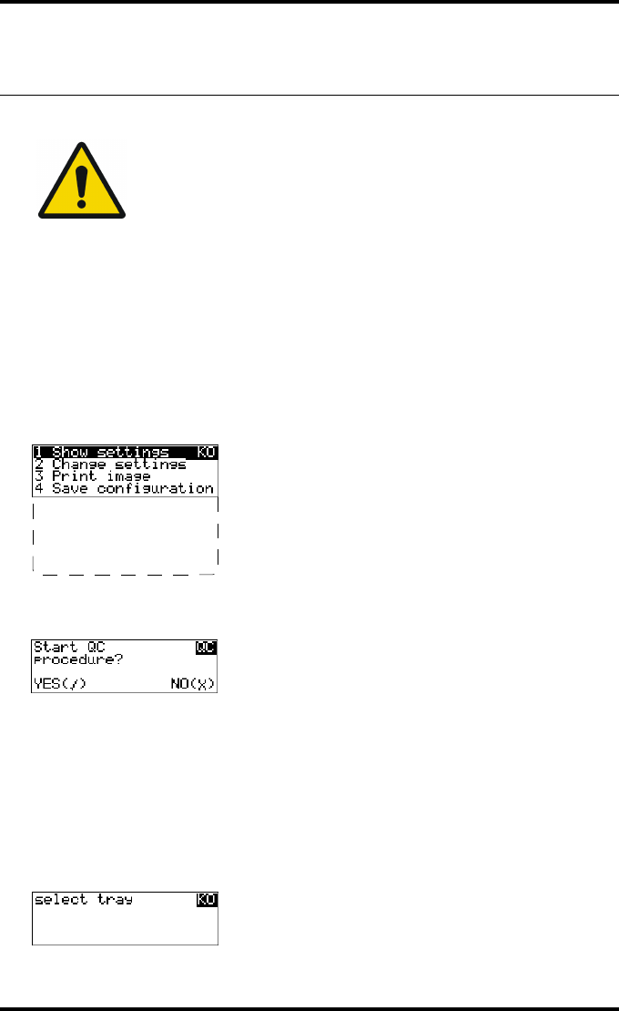
2Press the Key-operator key to enter the Key-operator mode.
3Press the down key seven times, followed by the ok key to select ‘QC’.
A confirmation screen appears:
4Do one of the following:
•Press the Confirm key (YES) to start the QC procedure and proceed with step 5.
•Press the Escape key (NO) to quit.
5Define the tray for printing.
The ‘Select tray’ screen appears:
WARNING: This test must be performed every day before any clinical film
can be processed.
5 Restore config.
6 Calibration
7 Service Actions
8 Quality Control
9 Installation
1.Upper tray
2.Lower tray
117
2852 A EN 20070205
DRYSTAR AXYS
6Press the Up/Down arrow keys to select the desired tray, followed by the Con-
firm key.
The following screens appear successively:
The Drystar AXYS will automatically print the QC test image.
After the image is printed, the system will display all measured optical density values:
7Record the Base + Fog, low, mid and high density values on Charts 2A and 2B
(‘Drystar AXYS Daily Density Control Chart’). Also record the date and time of
the test on the charts and on the QC mammography test images. Refer to Refer
to “Charts for mammography QC (optional)” on page 155.
8Press the Confirm key to return to the main menu.
9Press the ok key to return to the main menu.
WARNING: In case the measure results are not within the aim
values, the reason for the unacceptable density variations must be
identified and resolved before any further clinical films can be
processed. This may include repeating the film calibration
procedure.
WARNING: For possible causes of non-compliance and the
respective actions, refer to “Preventive maintenance schedule” on
page 121 and “Maintaining image quality and resolving image
quality problems” on page 258 (Reference manual).
DD: 1.56
(Densitometer=MB924)
The density levels are displayed, e.g:
Max D: x.x Hi D: 2.23
Mid D: 1.13 Lo D: 0.4
Base+Fog: 0.20
DD: x.xx
118 2852 A EN 20070205
DRYSTAR AXYS
Performing the Weekly QC tests for mammography
application (DT 2 Mammo) (optional)
Spatial Resolution, Artifact Test and Low Contrast Visibility
To identify artifacts and verify spatial resolution you must perform the follow-
ing test weekly or as needed for troubleshooting image quality problems.
Procedure
1First, print out the QC mammography test image. Refer to “Performing the daily
QC test for mammography application (DT 2 Mammo) (optional)” on page 116.
2Check the QC test image visually for artifacts: no significant disturbing artifacts
should be visible.
3Check the spatial resolution.
The test film also shows three squares which each contains an oval. These 3 ovals con-
tain 3 groups, each having 5 dots. All five dots of each group must be visible with a
magnifying glass. The smallest cluster of 5 dots is only visible if the viewing conditions
are good.
4Check the Low Contrast Visibility at both the high (100 / 95%) and low end
(0 / 5%) of the density scale. You should be able to see the circle in the square
(refer to item 1 on the “QC test image for mammography applications
(DT 2 Mammo) (optional)” on page 107) and the upper circle (refer to item 2
on the “QC test image for mammography applications (DT 2 Mammo)
(optional)” on page 107).
WARNING: Good viewing conditions are important for the correct
interpretation of both diagnostic and test images. Make sure that the light
box intensity (luminance) is 3000 and 6000 cd/m² (4500 and 6500 °K)
for mammography. Use a magnifying glass and use shutters to collimate.
Make sure the ambient light is low.

119
2852 A EN 20070205
DRYSTAR AXYS
5Record these values on Chart 3 (‘Drystar AXYS Artifacts and Spatial Resolution
Control Chart’). Refer to “Charts for mammography QC (optional)” on
page 155.
WARNING: In case of significant artifacts, insufficient spatial
resolution or failure of any other recommended QC tests, the
cause of the problem must be identified, and corrective action
must be taken before the Drystar AXYS can be used for any further
clinical imaging.
WARNING: Refer to “Preventive maintenance schedule” on
page 121 and “Maintaining image quality and resolving image
quality problems” on page 258 (Reference manual), or call your
local Agfa service organization.
120 2852 A EN 20070205
DRYSTAR AXYS
Performing the Annual QC tests for mammography
application (DT 2 Mammo) (optional)
Geometric Consistency Test
To be able to notice fluctuations in image size and aspect ratio, you must per-
form this procedure once a year.
Procedure
1First, perform the daily test.
2Measure the distances A and B of the geometric square on the QC mammogra-
phy test image. Refer to “Establishing the image geometry reference values for
mammography application (DT 2 Mammo) (optional)” on page 112.
3Record these values as measured distances A and B on Chart 4 (‘Drystar AXYS
Geometric Consistency Control Chart’). Refer to “Charts for mammography QC
(optional)” on page 155.
4Compare the measured A and B dimensions with the reference dimension val-
ues, Aref and Bref on Chart 4 (‘Drystar AXYS Geometric Consistency Control
Chart’). Refer to “Charts for mammography QC (optional)” on page 155.
The differences between the measured dimensions of A and B and the reference val-
ues A ref and B ref should be less than or equal to 1.0%.
5Check for image distortion.
6Calculate the aspect ratio by dividing A by B.
The result must be 1 +/- 0.01
WARNING: Make sure to measure distance A from the left edge of
the left line to the right edge of the right line and distance B from
the upper edge of the upper line to the lower edge of the lower
line.
WARNING: We strongly recommend using a 30 cm (12-inch)
machinist scale with 0.5 mm divisions (1/64 inch).
WARNING: If the image size or distortion values are outside of
limits, contact Agfa service to resolve the problem.
121
2852 A EN 20070205
DRYSTAR AXYS
Preventive maintenance schedule
The Drystar AXYS is designed for trouble-free operation. Maintenance and
cleaning involve only some minor user tasks. Refer to the following pages for
the appropriate cleaning procedure.
Safety guidelines
QDo not lubricate the printer.
QDo not attempt to disassemble the printer.
QDo not touch the resistor line of the print head.
QAlways switch off the Drystar AXYS and disconnect the power cord from the
outlet before carrying out any maintenance work inside the printer.
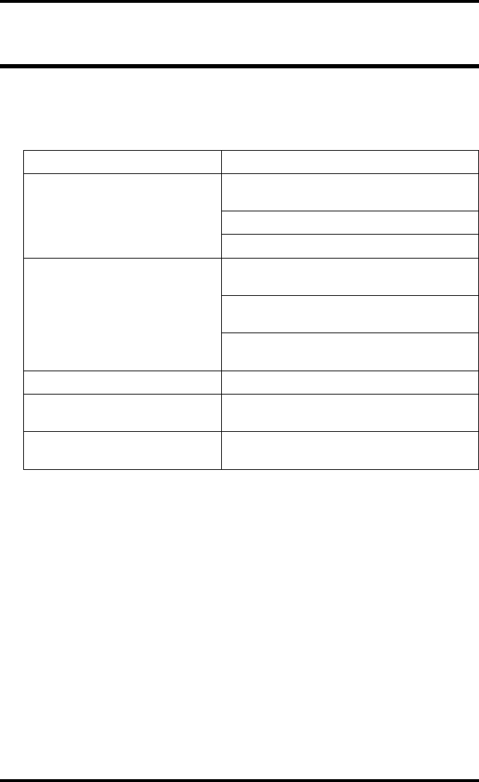
Interval What to do?
Ad hoc “Cleaning the exterior” on page 122
When image quality tends to
degrade. An appropriate warning
message is displayed.
“Cleaning the print head” on page 123
WARNING: To prevent damage to the printer while performing
maintenance, observe the following safety precautions:
Caution: Film jam removal or cleaning the printer head can be done
without switching the power off. Nevertheless, care should be taken
and the “Safety Directions” on page 43 should be respected.

122 2852 A EN 20070205
DRYSTAR AXYS
Cleaning the exterior
Procedure
1Switch off the Drystar AXYS by following the procedure as described in
“Switching off the Drystar AXYS” on page 63
2Remove the power plug from the socket.
3Wipe the exterior of the printer with a clean, soft, damp cloth.
Use a mild soap or detergent if required but never use an ammonia–based cleaner. Be
careful not to get any liquid in the power cord port.
4Plug in the printer and switch it on by following the procedure as described in
“Switching on the Drystar AXYS” on page 48.
123
2852 A EN 20070205
DRYSTAR AXYS
Cleaning the print head
Procedure
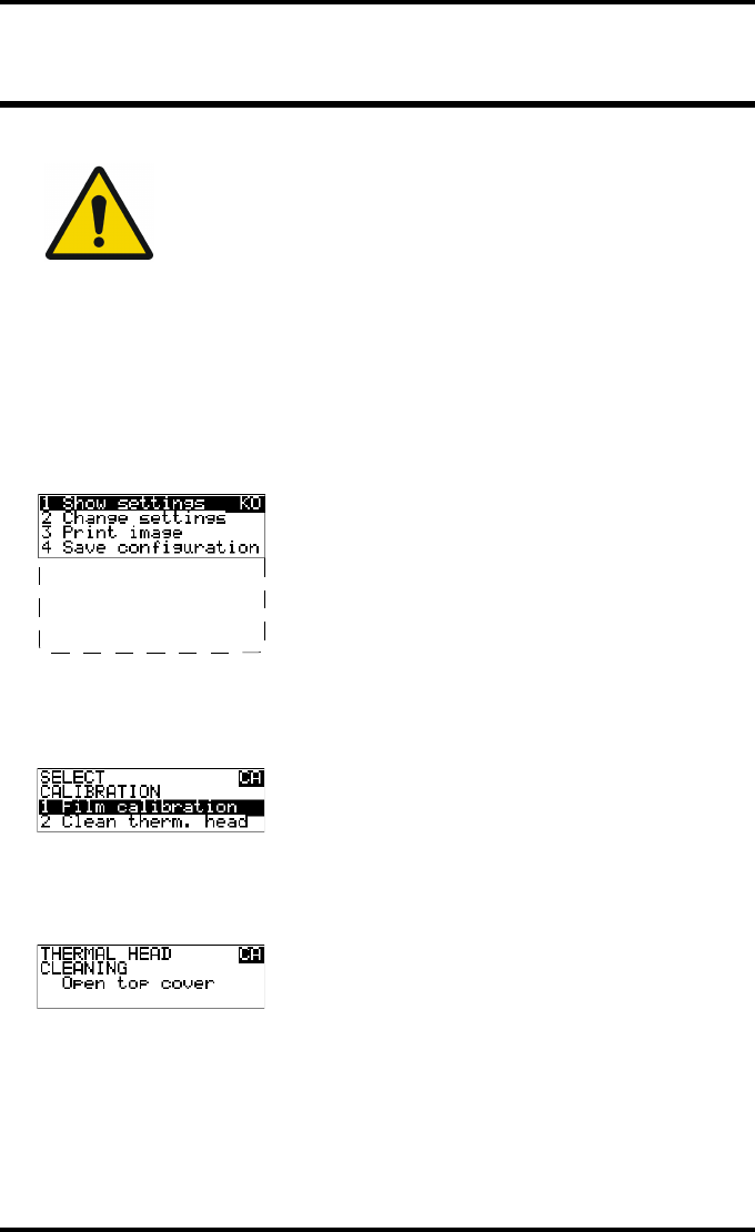
1Press the Key-operator key to enter the key-operator mode.
2On the key-operator main menu, press the Down key five times, followed by the
Confirm key to select ‘Calibration’.
3On the Select calibration menu, press the Down key, followed by the Confirm
key to select ‘Clean therm. head’.
4The ‘Thermal head cleaning’ screen will give step-by-step instructions on what
to do:
WARNING: Print head cleaning must be done when image quality
problems occur.
5 Restore config.
6 Calibration
7 Service Actions
8 Quality Control
9 Installation
124 2852 A EN 20070205
DRYSTAR AXYS
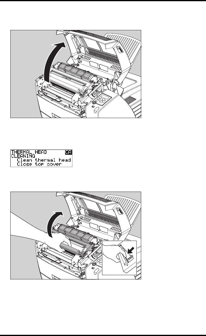
5Open the top cover.
6As soon as the top cover is opened, the ‘Thermal head cleaning’ screen contin-
ues giving the following instructions:
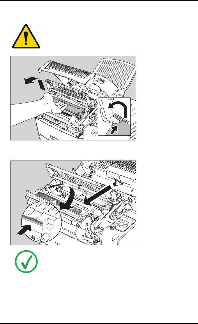
7Open the hold-down bracket.
125
2852 A EN 20070205
DRYSTAR AXYS
8Open the print head unit.
9Locate and check on sight the print head resistor line.
WARNING: The print head unit can be warm.
Note: Be careful not to touch the print head resistor line with your fingers.
126 2852 A EN 20070205
DRYSTAR AXYS
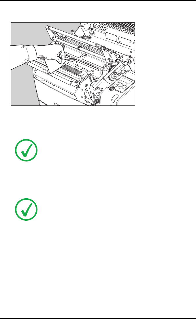
10 Clean the print head resistor line.
Gently pass over the resistor line a few times with a lint free cloth, slightly moistened
with Isopropyl alcohol or Ethanol.
Do this only in one direction, i.e. from left to right, without lifting the cloth.
11 Close the print head unit, the hold-down bracket and finally the top cover.
After you have cleaned the print head resistor line and you have closed the top cover,
you will return automatically to the Select calibration menu (see step 3).
12 Press the Escape key to return to the key-operator main menu.
Note: Do not apply any pressure on the print head because this pressure
may cause damage on the interconnections underneath the print head.
Note: If residue dust is present as part of the cleaning procedure it will
disappear after a few prints.
127
2852 A EN 20070205
DRYSTAR AXYS
Troubleshooting checklist
The table below lists some general problems, which can occur when working
with the Drystar AXYS.
QThe Drystar AXYS does not print.
Action Refer to the Reference manual
Check the Drystar AXYS
“Checking the status indicator LED” on
page 241
“Checking the connections” on page 242
“Checking the print queue” on page 244
Remove a jammed film
“Film input tray jams” on page 130 of this
manual
“Film transport jams (clearing from the top)”
on page 133 of this manual
“Unauthorized opening of the printer” on
page 136 of this manual
Resolve error messages “Checking error messages” on page 243
Handle CF-card errors “Checking CF-card error messages” on
page 244
Resolve film identification
problems
“No identification code detected” on
page 138 of this manual
128 2852 A EN 20070205
DRYSTAR AXYS
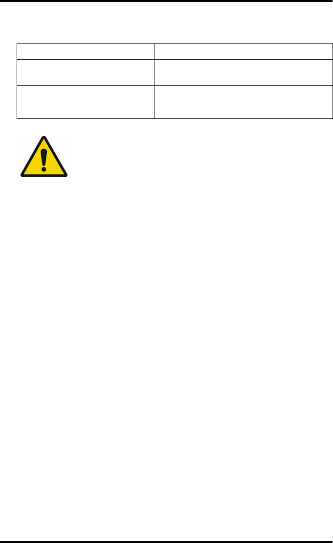
QThe quality of the printed images is bad (printing remains possible).
Action Refer to
Resolve film quality problems “Persistent white dots or lines appear in the
transport direction” on page 261
Resolve warning messages “Warning messages” on page 262
Resolve maintenance messages “Maintenance messages” on page 263
WARNING: Have electrical or mechanical defects repaired by
skilled personnel only!
129
2852 A EN 20070205
DRYSTAR AXYS
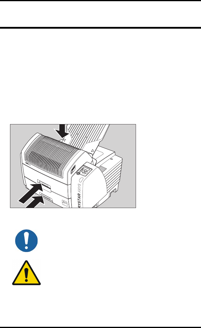
Clearing of film jams
A film jam can be situated either:
QIn the input tray section. Refer to “Film input tray jams” on page 130 .
QIn the top section. Refer to “Film transport jams (clearing from the top)” on
page 133 .
Jams can be caused by:
QOpening the top cover or input tray while a film is actually being printed. Refer
to “Unauthorized opening of the printer” on page 136 .
QLoading films incorrectly. Refer to “Film identification problems” on page 137 .
Caution: Film jam removal or cleaning the printer thermal head can be
done without switching the power off. Nevertheless, care should be
taken and the following instructions should be respected:
WARNING: Never reuse a jammed film. This may cause damage to
the thermal head and/or dust problems.
Film feed jams (clearing
from the input tray)
Film transport jams
(clearing from the
top section)
130 2852 A EN 20070205
DRYSTAR AXYS
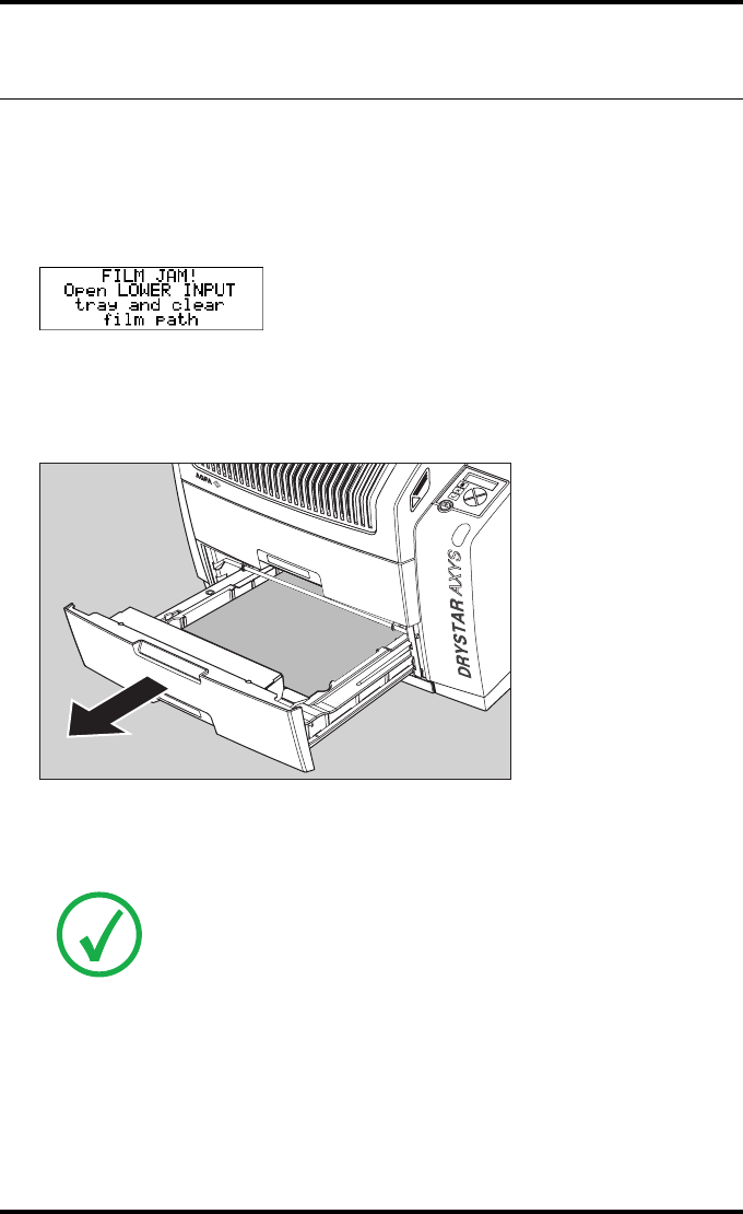
Film input tray jams
A film jam in the input tray can occur when the Drystar AXYS is opened while a
film is currently printed, or when an individual film is incorrectly inserted in
the input tray. Refer also to “Film identification problems” on page 137 .
The following screen indicates that a jam occurred in the input tray.
To remove a jammed film in the input tray:
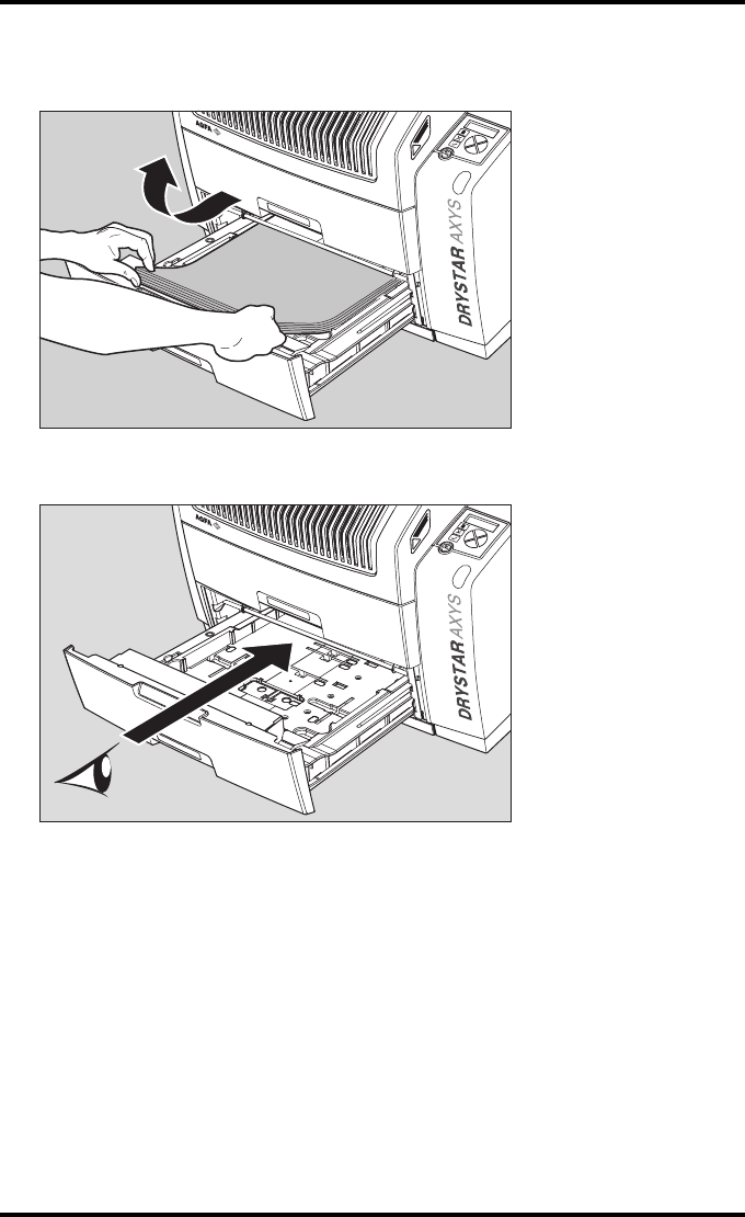
1Open the film input tray.
If a film is jammed, gently remove the sheet. Reposition the film stack in the film tray,
making sure that all the sheets are kept correctly
(refer to “Loading films” on page 76 ).
Note: Never use force to clear the jammed film. If it is not possible to gently
remove the jammed film, call your local service organization.
131
2852 A EN 20070205
DRYSTAR AXYS
2To get a clear view, it may be necessary to remove any remaining film sheets,
including the protective (white) sheet.
3Check if the film feed section of the input tray is clear.
Reposition the film stack in the film tray, making sure that all the sheets are
kept correctly in place (refer to “Loading films” on page 76).
132 2852 A EN 20070205
DRYSTAR AXYS
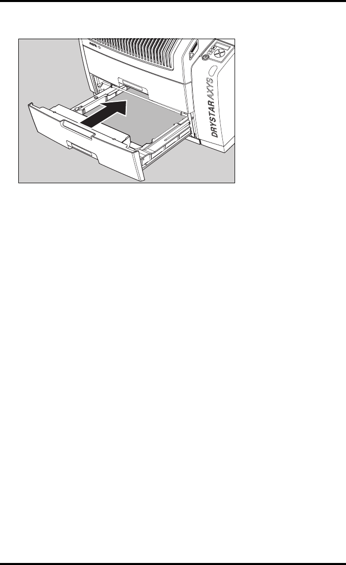
4Close the film input tray.
133
2852 A EN 20070205
DRYSTAR AXYS
Film transport jams (clearing from
the top)
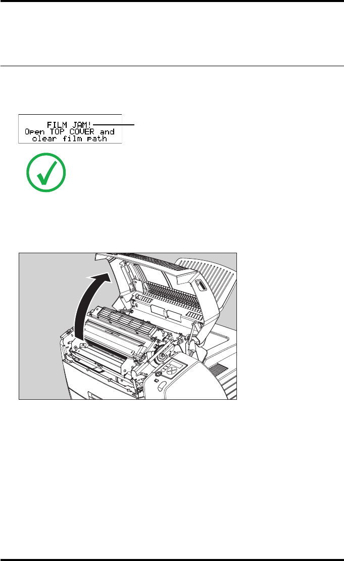
The following screen indicates that a jam occurred in the upper section of the
film transport system.
To remove a jammed film in the transport system:
1Open the top cover.
Note: Please note that instructions for removing a film jam in the transport
section are present on a sticker at the inside of the top cover.
Blinking
134 2852 A EN 20070205
DRYSTAR AXYS
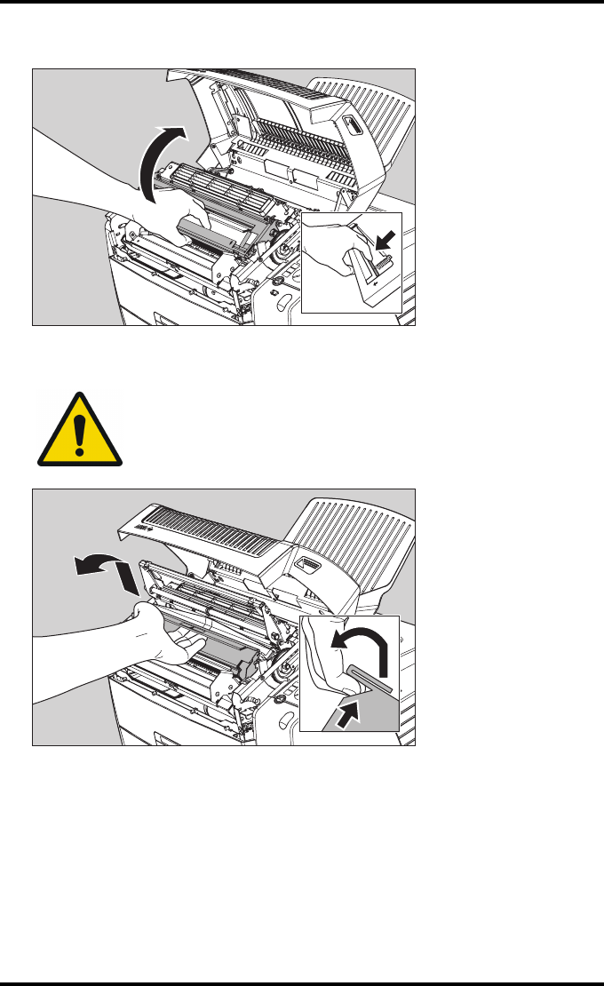
2Open the hold-down bracket.
3Open the print head unit.
WARNING: The print head unit can be warm.
135
2852 A EN 20070205
DRYSTAR AXYS
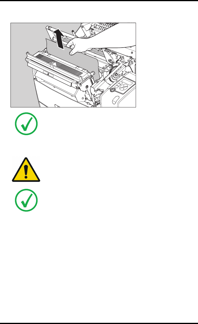
4Gently remove the film sheet(s).
5If the film jam has been cleared, close the printer. You can resume work.
Note: Never use force to clear the jammed film. If it is not possible to gently
remove the jammed film by pressing the transport buttons, proceed with
the procedure as follows.
Note: Verify that no film sheets remain in the print head compartment.
WARNING: Never reuse a jammed film. This may cause damage to
the thermal head and/or dust problems.
Note: If the jam is still not cleared, call your local service organization.
136 2852 A EN 20070205
DRYSTAR AXYS
Unauthorized opening of the printer
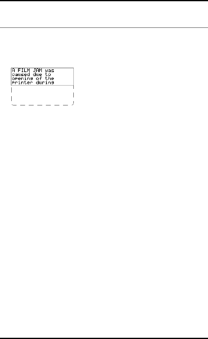
A jam can be caused by opening the printer covers or one of the input trays
while a film is actually being printed.
The following screen indicates that a jam has occurred:
1Remove the jammed sheet.
Refer to “Clearing of film jams” on page 129 .
2Press the Confirm key to continue.
3Make sure to follow carefully the procedures as described in this manual before
attempting to open the printer.
Refer to “Switching off the Drystar AXYS” on page 63 .
Refer to “Switching off the Drystar AXYS” on page 63 .
printing. Next time
wait until printer
is in "Ready"
condition.

137
2852 A EN 20070205
DRYSTAR AXYS
Film identification problems
When you load a new film pack, the new Film Identification tag is read and the
tray film format and type are set based upon the info in the Film Identification
tag (RF-tag).
This tag is only readable when the film pack is inserted in the correct way.
There are three possible error messages regarding film identification:
Q“No identification code detected” on page 138
Q“Invalid content of Film Identification tag” on page 141
Q“Invalid content of Film Identification tag” on page 141
The following sections describe the solution for each of these problems in more
detail.
138 2852 A EN 20070205
DRYSTAR AXYS
No identification code detected
This error message appears when the Film Identification tag is not readable.
There are two possible solutions for this problem:
QReload the current film pack or load another film pack
QOverrule the Film Identification tag of the film pack
To reload the current or another film pack
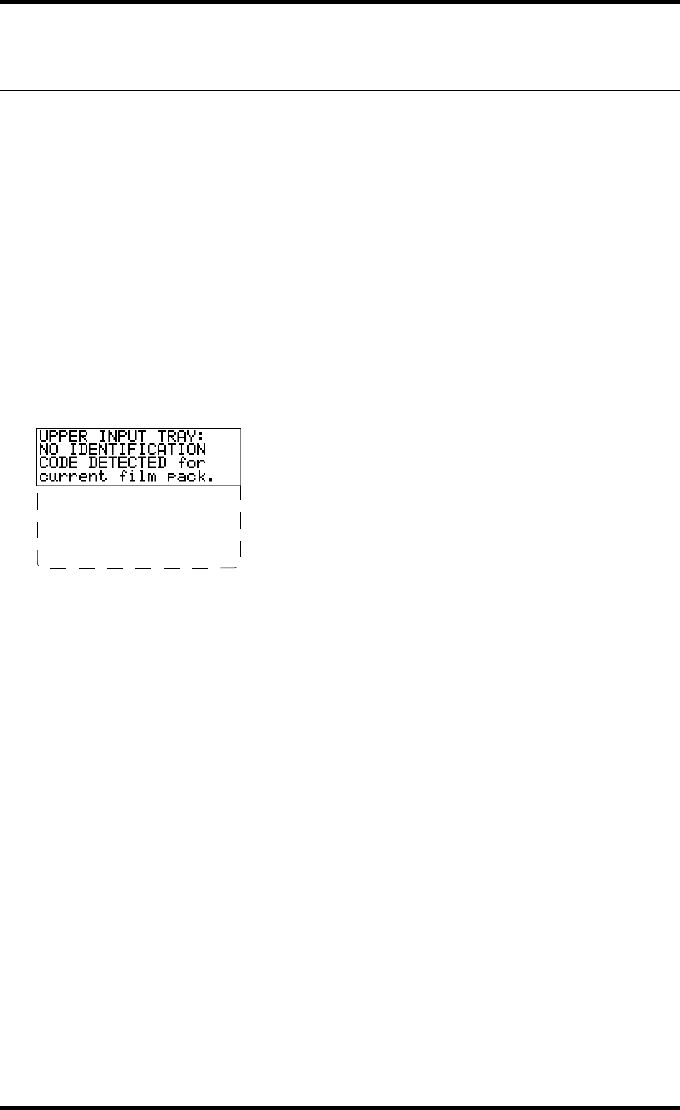
1In case the Drystar AXYS does not start printing after re-inserting a film pack,
first check if this film pack is inserted correctly.
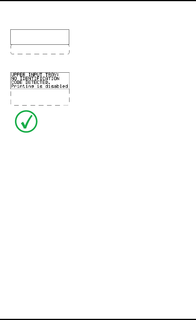
If the Drystar AXYS still does not resume printing, the following message will appear:
2Open the input tray and check again if the film pack is inserted correctly. If you
re-insert the film pack, the Drystar AXYS will perform the same check sequence
until printing is resumed.
Remove and re-insert
film pack -including
protective sheet-
properly. follow
loading instructions
139
2852 A EN 20070205
DRYSTAR AXYS
To overrule the Film Identification tag of the film pack
If the “Overrule RF-tag Reading” setting is active, you can overrule the Film
Identification tag setting of the current film pack. In this case you can continue
printing using a limited Maximum Density.
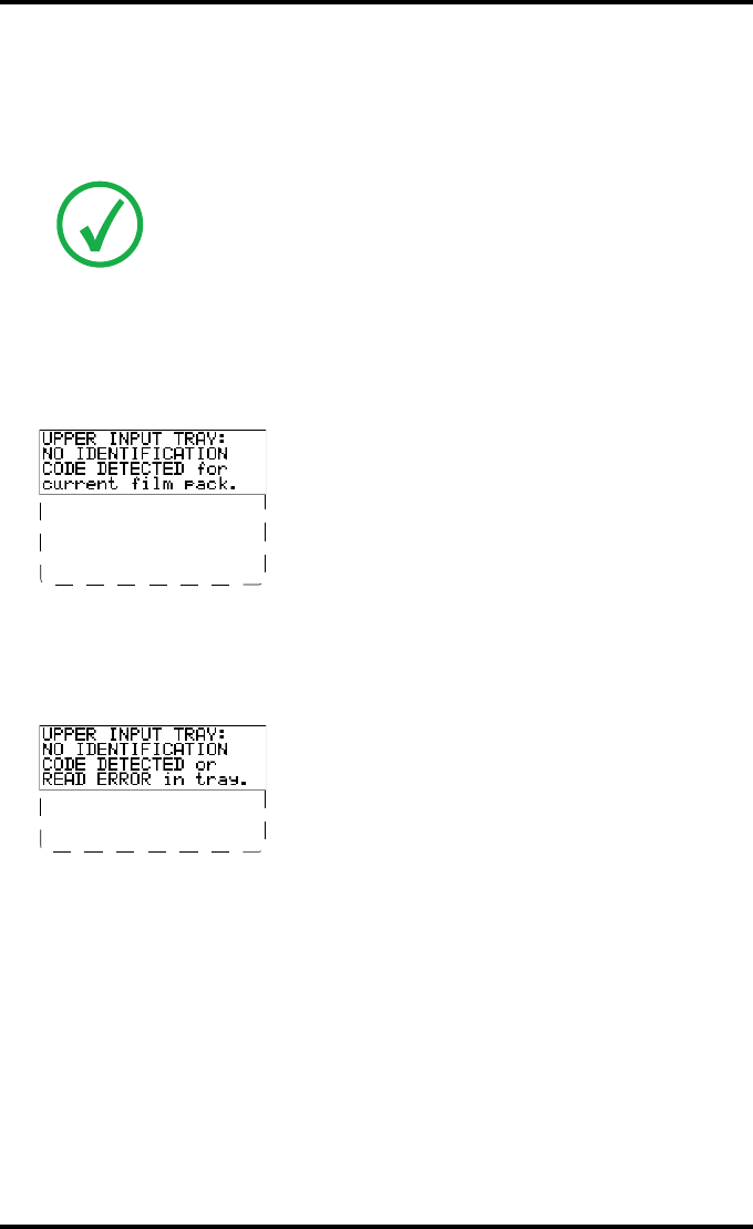
1In case the Drystar AXYS does not start printing after inserting a new film pack,
check if this film pack is inserted correctly.
If the film pack is inserted correctly and the Drystar AXYS does not resume printing,
the following message will appear:
2To continue with the current (unidentified) film pack, press the Continue but-
ton.
The following message is displayed:
If you wish, you can try again to re-insert the current or an other film pack. Open the
input tray to initiate the loading sequence. If you re-insert a film pack, the
Drystar AXYS will perform the check sequence.
Note: Only your local service organization has the possibility to enable the
“Overrule RF-tag Reading” setting!
Remove and re-insert
film pack -including
protective sheet-
properly. follow
loading instructions
Please INSERT
CURRENT FILM PACK or
call service.
140 2852 A EN 20070205
DRYSTAR AXYS
3Press the Confirm button.
•If the “Overrule RF-tag Reading” Setting is active, the following message is displayed:
•If the “Overrule RF-tag Reading” Setting is not activated, the following message will
be displayed:
4Press the Confirm key again to resume printing using a limited Maximum Den-
sity.
Note: In this case, press the Confirm key to initiate the loading procedure
again or call your local service organization to enable the “Overrule RF-tag
Reading” Setting.
OVERRULE
IDENTIFICATION CODE
IS ACTIVE
Dmax is limited due
to safety reasons
Re-enable printing
by inserting correct
film media pack.
141
2852 A EN 20070205
DRYSTAR AXYS
Invalid content of Film Identification
tag
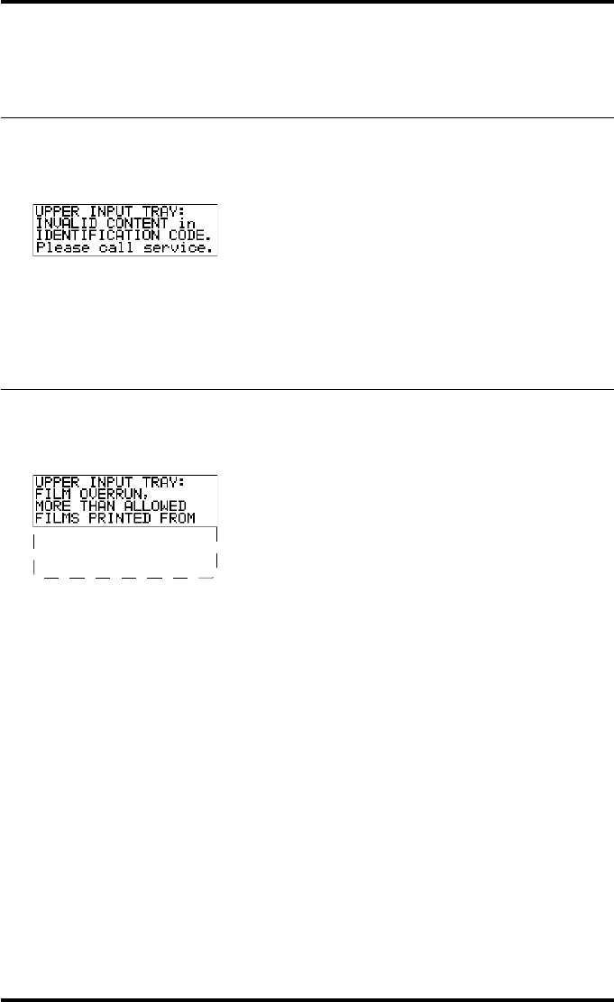
When you insert a new film pack with invalid content in the Film Identification
tag, the following message is displayed:
Try loading another film pack, or call your local service organization to resolve
this problem.
Film overrun from current pack
The following message is presented when more than 110 copies are printed
from the current film pack:
Reload a new film pack to resolve this problem.
THIS PACK. please
insert other film
pack.

142 2852 A EN 20070205
DRYSTAR AXYS

A Equipment information
sheet
This appendix covers the following sections:
❑Specifications
❑Viewing the system info area on a film
144 2852 A EN 20070205
DRYSTAR AXYS
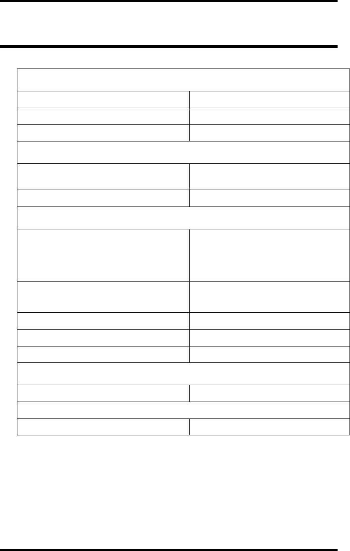
Specifications
Product description
Type of product Printer
Commercial name Drystar AXYS
Original seller/manufacturer Agfa-Gevaert N.V.
Labelling
TÜV-, cULus-Certification Mark,
CE-marking
CCC Mark
Dimensions
Dimensions (approx. values in cm)
Unpacked: width 72.8, length 71.5,
height 67.6
Packed: width 89, length 100,
height 80
Weight Unpacked: approx. 90 kg
Packed: approx. 128 kg
RAM memory 512 Mb
Internal mass storage media Hard Disk
External mass storage media Compact Flash Type II
Electrical connection
Operating voltage 100-120 V; 220-240 V AC
No external main fuses
Mains frequency 50/60 Hz
145
2852 A EN 20070205
DRYSTAR AXYS
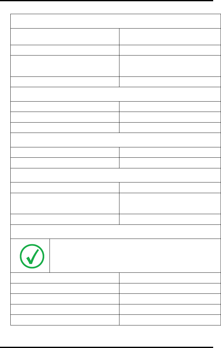
Network connectivity
Ethernet / connectors RJ45 twisted pair for 10/100Base-TX;
Serial RS232 connection
Network protocols (TCP/IP services) FTP, Telnet, HTTP
Image formats DICOM (Default)
TIFF
Postscript Not available
Power consumption - heat dissipation
During operation 250 W - 900 kJ/h
In stand-by 70 W - 252 kJ/h
Peak power (absolute max. rating) 530 W - 1908 kJ/h
Protection against
Electrical shocks Class 1 (grounded)
Ingress of water IPXØ
Environmental conditions (operation)
Room temperature Between +15°C and +30°C
Relative humidity Between 20% and 75%
Note: Films may not become wet!
Atmospheric pressure 70 kPa - 106 kPa
Environmental storage conditions
Note: Climate conditions for storage are in accordance with EN60721-3-1-
class 1K4.
Room temperature Between -25°C and 55°C (storage)
Relative humidity Between 10% and 100%
Absolute humidity Between 0.1 g/m3 and 35 g/m3
Rate of change of temperature 1°C/min
Atmospheric pressure 70 kPa - 106 kPa
146 2852 A EN 20070205
DRYSTAR AXYS
Environmental transport conditions
Note: Climate conditions for transport are in accordance with
EN60721-3-2-class 2K4.
Temperature Between -40°C and 70°C (transport)
Relative humidity not combined with
rapid temperature changes 95% at +45°C
Noise emission (method of measurement in accordance with DIN 45635 part 19)
During operation Max. 64 dBA
In stand-by Max. 54 dBA
Total acoustic A-weighted noise power
During operation 62 dB ( = 6.4Bel = 6.4B)
In stand-by 53 dB ( = 5.3Bel = 5.3B)
Consumables
Drystar DT 2B and Drystar DT 2C 8x10”, 10x12”, 11x14”, 14x14” and
14x17”film sizes
Drystar DT 2 Mammo (optional) 8x10”, 10x12” and 11x14” film sizes
Print technology
Direct thermal printing
Reliability
Estimated product life
(if regularly serviced and maintained
according to Agfa instructions)
> 5 years
Service interventions Max. 2 interventions / 3 years
Earthquake (standard) Meets the CA requirements
Imaging Array - Diagnostic area - General radiography
8x10”
8” dimensions 10” dimensions
pixels mm pixels mm
3852 192,6 4880 244
147
2852 A EN 20070205
DRYSTAR AXYS
10x12”
10” dimensions 12” dimensions
pixels mm pixels mm
4880 244 5860 293
11x14”
11” dimensions 14” dimensions
pixels mm pixels mm
5376 268,8 6922 346,1
14x14”
14” dimensions 14” dimensions
pixels mm pixels mm
6882 344,1 6882 344,1
14x17”
14” dimensions 17” dimensions
pixels mm pixels mm
6922 346,1 8368 418,4
Imaging Array - Diagnostic area - Mammography (optional)
8x10”
8” dimensions 10” dimensions
pixels mm pixels mm
3828 191,4 4958 247,9
10x12”
10” dimensions 12” dimensions
pixels mm pixels mm
4892 244,6 5810 290,5
11x14”
11” dimensions 14” dimensions
pixels mm pixels mm
5376 268,8 6922 346,1
Imaging Array - Diagnostic area - General radiography
148 2852 A EN 20070205
DRYSTAR AXYS
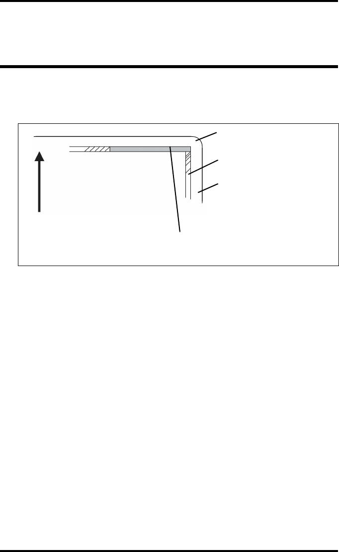
Viewing the system info area on a
film
On the top right corner of each film, a “System info” area will be printed.
This info can only be read using a magnifying glass.
The System info area contains info about:
QPrinter: (serial number, densitometer info, film counts, software version, etc.),
QController (image source, date, time, etc.).
For more detailed information, refer to the Drystar AXYS Service documenta-
tion.
Film
Diagnostic area
Clear border
Black border
System info area
Transport direction

B Quality Control Charts
This appendix covers the following topics:
❑Charts for general radiography QC
❑Charts for mammography QC (optional)
150 2852 A EN 20070205
DRYSTAR AXYS
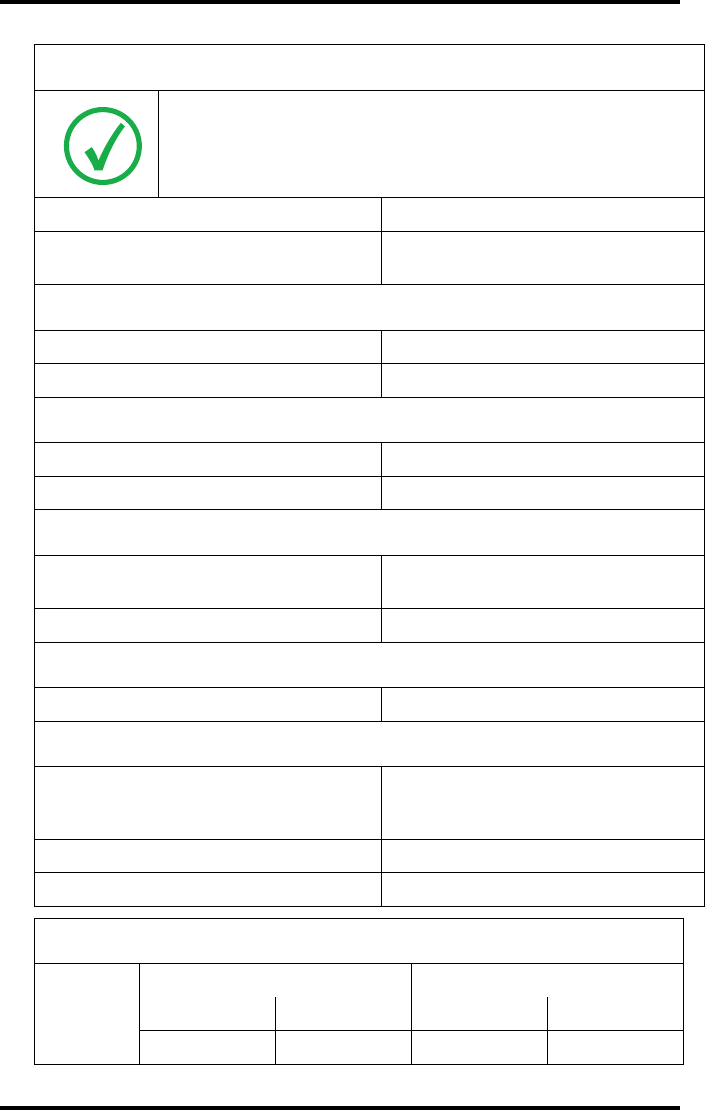
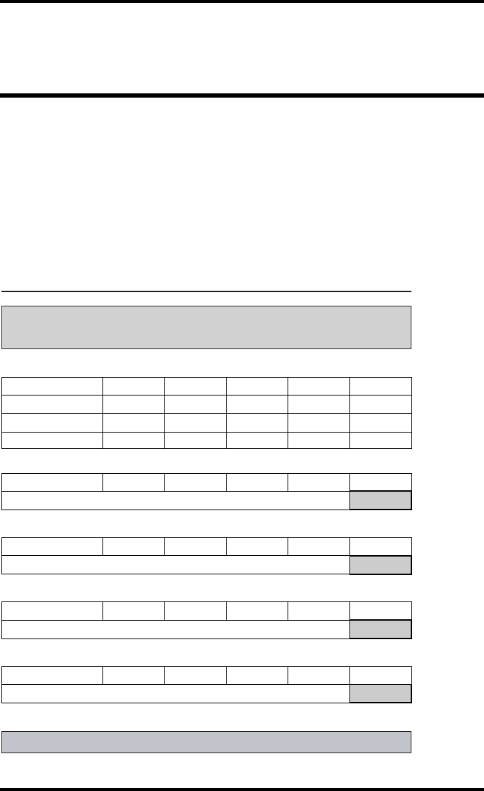
Charts for general radiography QC
Drystar AXYS : Determination of Operating Levels
Imager Type: __________ Serial #: _________________ Date ____________________
Input Tray ________________Film Type: ____________ Emulsion #: ______________
Densitometer: _________________ (default selection)
Day 1 Day 2 Day 3 Day 4 Day 5
Month
Day
Initials
Low Density
Average of 5 Values = calculated reference “Low Density” level
Mid Density
Average of 5 Values = calculated reference “Mid Density” level
High Density
Average of 5 Values = calculated reference “High Density” level
Step 1: Print QC Test images on five consecutive days. Record the optical densities
measurements in the tables below. After five days, average the values to determine
the operating (aim) levels for each of the parameters.
Step 2: Copy the calculated reference levels to Charts 2A/B ('Daily Density Control Chart')
General radiography applications
Quality Control for Chart 1
151
2852 A EN 20070205
DRYSTAR AXYS
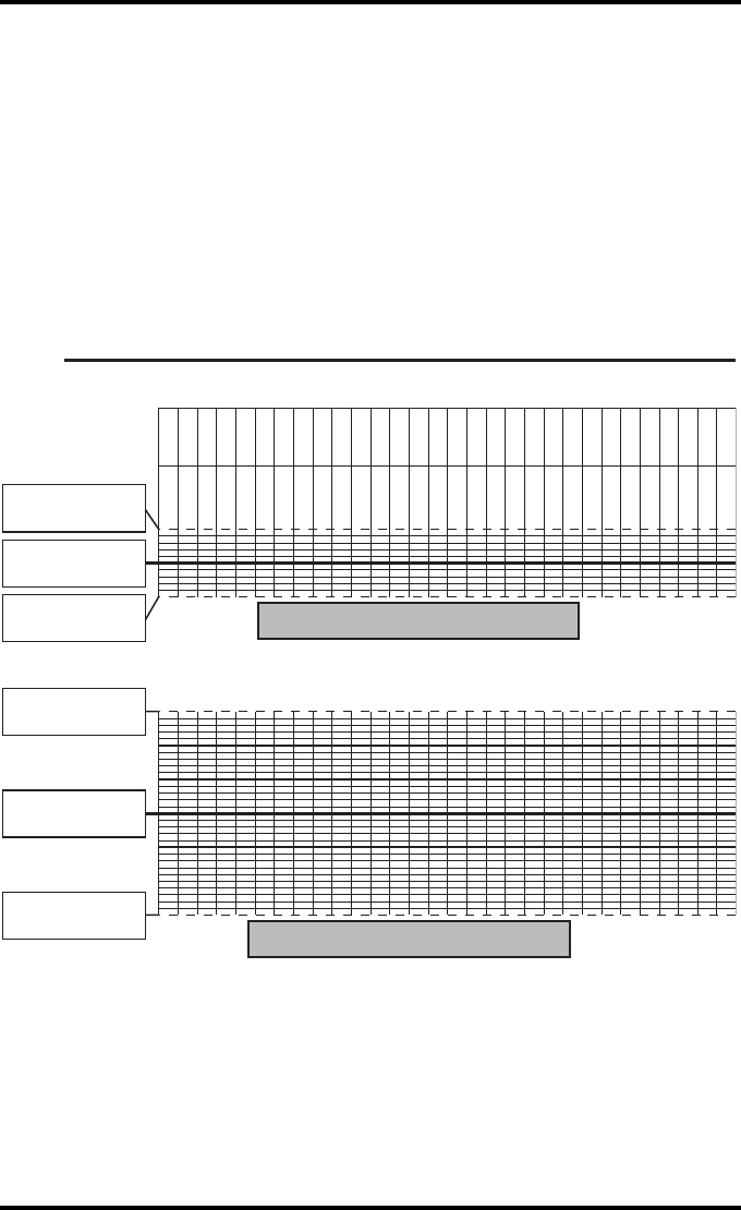
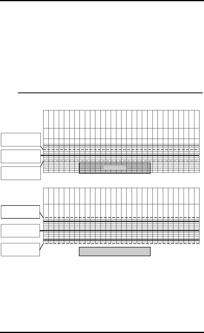
Drystar AXYS Daily Density
Control Chart
Imager Type: __________ Serial #: _____________ Film Type:____________ Emul #:___________
_
Input Tray:_________
Densitometer: ____________________ (default selection)
Date :
Initia ls:
Low Density
Mid Density
Upper Control limit =
+0.05
Calculated Reference
Low Density Level
Lower Control Limit =
-0.05
Upper Control limit =
+0.15
Calculated Reference
Mid Density Level
Lower Control Limit =
-0.15
General radiography applications
Quality Control for Chart 2A
152 2852 A EN 20070205
DRYSTAR AXYS
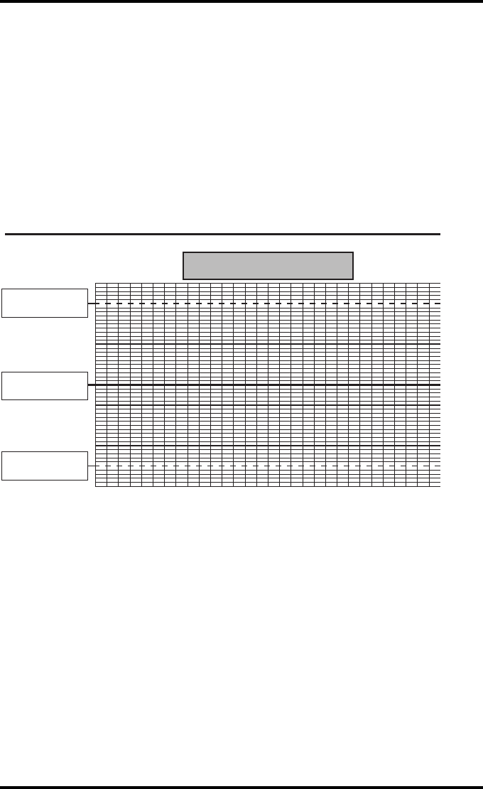
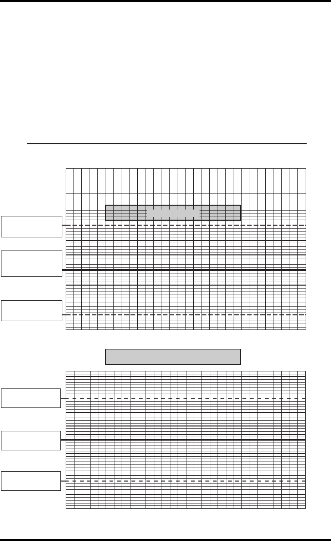
Drystar AXYS Daily Density
Control Chart
Imager Type: __________ Serial #: _____________ Film Type:____________ Emul #:___________
_
Input Tray:_________
Densitometer: ____________________ (default selection)
High Density
Upper Control limit =
+0.20
Lower Control Limit =
-0.20
Calculated Reference
High Density Level
General radiography applications
Quality Control for Chart 2B
153
2852 A EN 20070205
DRYSTAR AXYS
Drystar AXYS Artifacts and Spatial Resolution
Control Chart
Test Frequency: Weekly Drystar AXYS Serial # _____________
Input Tray: ____________
Initial Reference Test Date
Initial Reference Artifacts
Initial Reference Dot Visibility
Initial Reference Low Contrast
Month
Day
Artifacts
Visibility of all Dots
Month
Day
Artifacts
Visibility of all Dots
Month
Day
Artifacts
Visibility of all Dots
Month
Day
Artifacts
Visibility of all Dots
Month
Day
Artifacts
Visibility of all Dots
Low Contrast Visibility
Low Contrast Visibility
Low Contrast Visibility
Low Contrast Visibility
Low Contrast Visibility
General radiography applications
Quality Control for Chart 3
154 2852 A EN 20070205
DRYSTAR AXYS
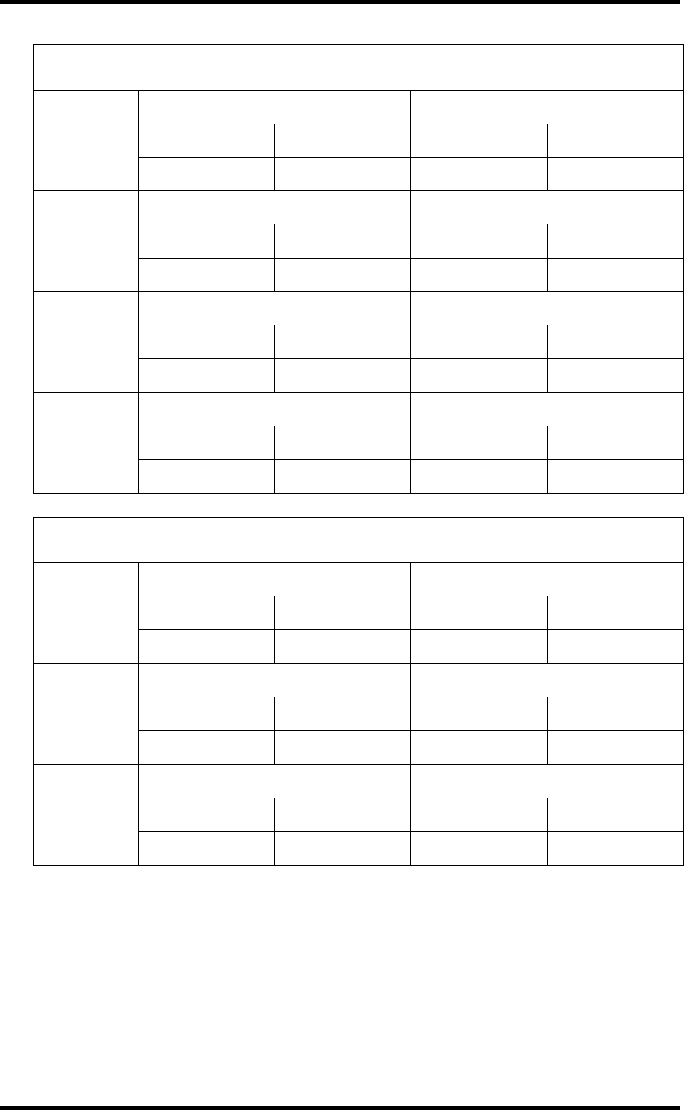
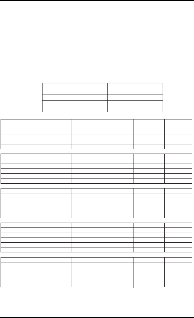
Drystar AXYS Geometric Consistency
Control Chart
Input Tray: _______________________
Test Frequency: Annually or as required Drystar AXYS Serial # ____________
_
Reference Dimensions
Date: Measured Dimensions
Date: Consistency Aspect Ratio
Aref A: A/Aref A/B
Bref B: B/Bref
Reference Dimensions
Date: Measured Dimensions
Date: Consistency Aspect Ratio
Aref A: A/Aref A/B
Bref B: B/Bref
General radiography applications
Quality Control for Chart 4
155
2852 A EN 20070205
DRYSTAR AXYS
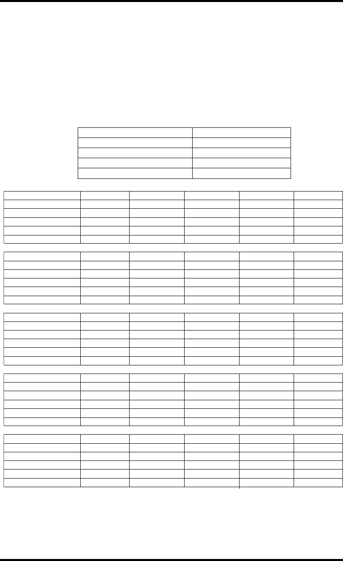
Charts for mammography QC
(optional)
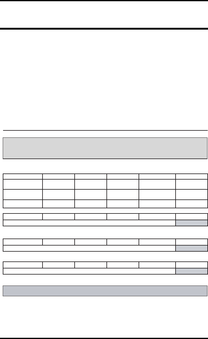
Drystar AXYS : Determination of Operating Levels
Imager Type: __________ Serial #: _________________ Date ____________________
Film Type: ____________ Emulsion #: ______________
Densitometer
: _________________ (default selection)
Step 1: Print QC Test images on five consecutive days. Record the optical densities
measurements in the tables below. After five days, average the values to determine
the reference levels for each of the parameters.
Mammography applications
Month
Day 1 Day 2 Day 3 Day 4 Day 5
Date
Initials
Average of 5 values = calculated reference "Base + Fog" level
Base + Fog
Average of 5 values = calculated reference "Low Density" level
Low Density
Average of 5 values = calculated reference "Mid Density" level
Mid Density
Average of 5 values = calculated reference "High Density" level
High Density
Step 2: Copy the calculated reference levels to Charts 2A/B ('Daily Density Control Chart')
Input Tray: _______________
Quality Control for Chart 1
156 2852 A EN 20070205
DRYSTAR AXYS
Drystar AXYS Daily Density
Control Chart
Imager Type: __________ Serial #: _____________ Film Type:____________ Emul #:__________
_
Densitometer: _________________ (default selection)
Mammography applications
Input Tray: ________
Quality Control for Chart 2A
Date:
Initials:
Upper Control limit =
+0.03
Calculated Reference
Base + Fog Level
Base + Fog
Low Density
Lower Control limit =
-0.03
Date:
Initials:
Upper Control limit =
+0.07
Calculated Reference
Low Density Level
Lower Control Limit =
-0.07
157
2852 A EN 20070205
DRYSTAR AXYS
Drystar AXYS Daily Density
Control Chart
Imager Type: __________ Serial #: _____________ Film Type:____________ Emul #:__________
_
Densitometer: _________________ (default selection)
Mammography applications
Input Tray: ________
Quality Control for
Chart 2B
Date:
Initials:
Upper Control limit =
+0.15
Lower Control limit =
-0.15
Calculated Reference
Mid Density Level
Mid Density
High Density
Upper Control limit =
+0.15
Lower Control Limit =
-0.15
Calculated Reference
High Density Level
158 2852 A EN 20070205
DRYSTAR AXYS
Drystar AXYS Artifacts and Spatial Resolution
Control Chart
Test Frequency: Weekly Drystar AXYS Serial # _____________
Initial Reference Test Date
Initial Reference Artifacts
Initial Reference Dot Visibility
Initial Reference Low Contrast
Month
Day
Artifacts
Visibility of all Dots
Month
Day
Artifacts
Visibility of all Dots
Month
Day
Artifacts
Visibility of all Dots
Month
Day
Artifacts
Visibility of all Dots
Month
Day
Artifacts
Visibility of all Dots
Low Contrast Visibility
Low Contrast Visibility
Low Contrast Visibility
Low Contrast Visibility
Low Contrast Visibility
Mammography applications
Input Tray: ____________
Quality Control for
Chart 3
159
2852 A EN 20070205
DRYSTAR AXYS
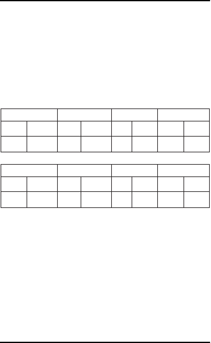
Drystar AXYS Geometric Consistency
Control Chart
Test Frequency: Annually or as required Drystar AXYS Serial # ____________
Reference Dimensions
Date: Measured Dimensions
Date: Consistency Aspect Ratio
Aref A: A/Aref A/B
Bref B: B/Bref
Reference Dimensions
Date: Measured Dimensions
Date: Consistency Aspect Ratio
Aref A: A/Aref A/B
Bref B: B/Bref
Mammography applications
Input Tray: ______________________
Quality Control for Chart 4

160 2852 A EN 20070205
DRYSTAR AXYS

161
2852 A EN 20070205
DRYSTAR AXYS

Printed in Belgium
Published by Agfa-Gevaert N.V., B-2640 Mortsel-Belgium
2852 A EN 20070205