Agilent Technologies Fs2010 Users Manual FS2010_11
FS2010 to the manual 795092d1-d8f7-4e73-a1b3-e6bcf61090cf
2015-02-02
: Agilent-Technologies Agilent-Technologies-Fs2010-Users-Manual-413174 agilent-technologies-fs2010-users-manual-413174 agilent-technologies pdf
Open the PDF directly: View PDF ![]() .
.
Page Count: 36

FuturePlus Systems Corporation
FS2010 Users Manual
For use with Agilent Logic Analyzers
Revision – 1.1
Copyright 2005 FuturePlus® Systems Corporation
FuturePlus is a trademark of FuturePlus Systems Corporation

2
How to reach us ......................................................................................... 4
Product Warranty....................................................................................... 5
Limitation of Warranty...................................................................................5
Exclusive Remedies....................................................................................................5
Assistance..........................................................................................................5
Introduction................................................................................................ 6
How to Use This Manual .................................................................................6
Analyzing the PCI-X Local Bus ................................................................ 7
Accessories Supplied ........................................................................................7
Minimum Equipment Required......................................................................7
Additional Equipment Required.....................................................................7
Signal Naming Conventions ............................................................................8
Determining which logic analyzer card is the Master...................................8
Configuration Files...........................................................................................9
Connecting the 167xx Agilent logic analyzer to the FS2010.......................10
How to install a PCI-X add-in card into the FS2010 ..................................10
System operation with the PCI-X add-in card ............................................10
Setting up the 167xx Analyzer.......................................................................11
Setting up the 1680/90/900 Analyzer ............................................................12
1680/90/900 Licensing....................................................................................12
Loading 1680/90/900 configuration files ......................................................12
Connecting the 1680/90/9xx Agilent logic analyzer to the FS2010 ............12
Offline Analysis ..............................................................................................13
The Format Menu ..........................................................................................16
The PCI-X Transaction Decode Software....................................................17
FS2010 Software and Timing mode........................................................ 18
The ADDR, ADDR_B and DATA variables............................................................18
The CYCLE variable ................................................................................................19
Bit Re-ordering.........................................................................................................20
State Analysis ........................................................................................... 21
Acquiring Data ...............................................................................................21
Configuring the Workspace for PCI-X Analysis.........................................22
The State Listing Display...............................................................................23
Functionality of the FS2010 Transaction Decode Software .......................25
Timing Analysis ....................................................................................... 26
Acquiring Data ...............................................................................................26
The Waveform Display..................................................................................27

3
Use of EyeFinder/Eyescan .............................................................................27
Transaction Viewer.................................................................................. 28
General Information................................................................................ 29
Characteristics................................................................................................29
State/Timing Adapter Probe Interface Compatibility ...............................................29
Card Edge Extender Connector ................................................................................29
Standards Supported.................................................................................................29
Power Requirements.................................................................................................29
Logic Analyzer Required..........................................................................................29
Number of Probes Used............................................................................................29
Minimum Clock Period (State).................................................................................29
Etch length................................................................................................................30
Operations.................................................................................................................30
Environmental Temperature .....................................................................................30
Altitude .....................................................................................................................30
Humidity...................................................................................................................30
Testing and Troubleshooting ....................................................................................30
Servicing...................................................................................................................30
Signal Connections.........................................................................................30
The State/Timing Adapter Probe interface pinout....................................................30
J2 Signal Connector ................................................................................ 31
J3 Signal Connections............................................................................. 33
J4 Signal Connections............................................................................. 35

4
How to reach us
For Technical Support:
FuturePlus Systems Corporation
36 Olde English Road
Bedford NH 03110
TEL: 603-471-2734
FAX: 603-471-2738
On the web http://www.futureplus.com
For Sales and Marketing Support:
FuturePlus Systems Corporation
TEL: 719-278-3540
FAX: 719-278-9586
On the web http://www.futureplus.com
FuturePlus Systems has technical sales representatives in several
major countries. For an up to date listing please see
http://www.futureplus.com/contact.html.
Agilent Technologies is also an authorized reseller of many
FuturePlus products. Contact any Agilent Technologies sales office
for details.

5
Product Warranty
This FuturePlus Systems product has a warranty against defects in material and
workmanship for a period of 1 year from the date of shipment. During the
warranty period, FuturePlus Systems will, at its option, either replace or repair
products proven to be defective. For warranty service or repair, this product must
be returned to the factory.
Due to the complex nature of the FS2010 and the wide variety of customer
target implementations, the FS2010 has a 30 day acceptance period by the
customer from the date of receipt. If the customer does not contact
FuturePlus Systems within 30 days of the receipt of the product it will be said that
the product has been accepted by the customer. If the customer is not satisfied
with the FS2010 they may return the FS2010 within 30 days for a refund.
For products returned to FuturePlus Systems for warranty service, the Buyer
shall prepay shipping charges to FuturePlus Systems and FuturePlus Systems
shall pay shipping charges to return the product to the Buyer. However, the
Buyer shall pay all shipping charges, duties, and taxes for products returned to
FuturePlus Systems from another country.
FuturePlus Systems warrants that its software and hardware designated by
FuturePlus Systems for use with an instrument will execute its programming
instructions when properly installed on that instrument. FuturePlus Systems does
not warrant that the operation of the hardware or software will be uninterrupted or
error-free.
The foregoing warranty shall not apply to defects resulting from improper or
inadequate maintenance by the Buyer, Buyer-supplied software or interfacing,
unauthorized modification or misuse, operation outside of the environmental
specifications for the product, or improper site preparation or maintenance. NO
OTHER WARRANTY IS EXPRESSED OR IMPLIED. FUTUREPLUS SYSTEMS
SPECIFICALLY DISCLAIMS THE IMPLIED WARRANTIES OF
MERCHANTABILITY AND FITNESS FOR A PARTICULAR PURPOSE.
THE REMEDIES PROVIDED HEREIN ARE BUYER’S SOLE AND EXCLUSIVE
REMEDIES. FUTUREPLUS SYSTEMS SHALL NOT BE LIABLE FOR ANY
DIRECT, INDIRECT, SPECIAL, INCIDENTAL, OR CONSEQUENTIAL
DAMAGES, WHETHER BASED ON CONTRACT, TORT, OR ANY OTHER
LEGAL THEORY.
Product maintenance agreements and other customer assistance agreements
are available for FuturePlus Systems products. For assistance, contact
Technical Support.
Limitation of
Warranty
Exclusive Remedies
Assistance

6
Introduction
The FS2010 is a 32/64 bit, 0 to 133Mhz PCI-X State and Timing adapter probe
for use with Agilent logic analyzers. This card has a universal card edge
connector and a 3.3v extender card connector. The FS2010 PCI-X State/Timing
adapter probe and extender card performs three functions.
• The first is to act as an extender card, physically extending a module up
approximately 1.5 inches from the motherboard connector.
• The second is to provide a complete timing analysis interface between any
PCI-X add-in slot and Agilent Logic Analyzers.
• The third is to provide a complete state analysis interface and software
decode of the PCI-X traffic between any PCI-X add-in slot and Agilent Logic
Analyzers.
The State/Timing Adapter Probe interface is a passive bus monitor which does
not assert any signals on the PCI-X bus. Because the FS2010 interface does
not actively buffer the PCI-X bus signals, negligible skew is introduced.
The configuration software on the diskette sets up the format menu of the logic
analyzer for compatibility with your PCI-X bus.
This manual is organized to help you quickly find the information you need.
• Analyzing the PCI-X Local Bus chapter introduces you to the FS2010 and
lists the minimum equipment required and accessories supplied for PCI-X
bus analysis.
• The State Analysis chapter explains how to configure the FS2010 to
perform state analysis on your PCI-X bus.
• The Timing Analysis chapter explains how to configure the FS2010 to
perform timing analysis on your PCI-X bus.
• The General Information chapter provides information on the operating
characteristics, the test point and cable header pinout and the mechanical
drawing for the FS2010 module.
How to Use This
Manual

7
Analyzing the PCI-X
Local Bus
This chapter introduces you to the FS2010 and lists the minimum
equipment required and accessories supplied for PCI-X Local Bus
analysis. This chapter also contains information that is common to both
state and timing analysis.
The FS2010 product consists of the following accessories:
• The FS2010 probe.
• 1 Diskette containing the configuration files and the FS2010 PCI-X
decoder for 167xx analyzer.
• A CD containing the setup file to install the configuration files and
protocol decoder on the 1680/90/900 analyzer or to use as an offline
viewer.
• This operating manual on CD, Quick Start sheet, and SW
Entitlement certificates for the software.
The minimum equipment required for analysis of a PCI-X Local Bus
consists of the following equipment:
• Agilent 16700 analysis frame with the 16715 analyzer card or better.
• Revision 2.80.00 or better of the Agilent Logic analysis frame
software.
• 1680/90/900 Logic analyzer or PC containing Agilent 1680/90/900
OS version 3.00.00 or better.
• The FS2010 Product
• A PCI-X target bus
The type of logic analyzer card used will determine the correct type of
termination adapter needed. For analyzer cards that use the 40 pin
header, 1671x, 1674x, 16750/1/2, 1691x you will need the E5385A
(FuturePlus number is FS1015) termination adapter cables. For
analyzer cards that use the 90 pin header, 16753/4/5/6, 1695x you will
need the E5378A (FuturePlus number is FS1014) termination adapter.
A total of 3 adapter cables are required for 64 bit data width capture.
Accessories
Supplied
Minimum Equipment
Required
Additional
Equipment Required
8
This operating manual uses the same signal notation as the PCI-X
LOCAL BUS SPECIFICATION - REVISION 1.0 That is, a # symbol at the
end of a signal name indicates that the signal’s active state occurs when
it is at a low voltage. The absence of a # symbol indicates that the signal
is active at a high voltage.
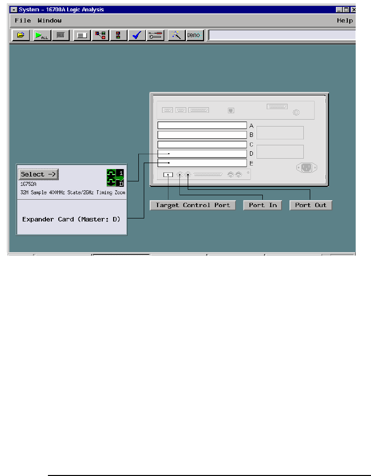
When connecting the logic analyzer cards to the FS2010 it is necessary
to know which logic analyzer card in which slot has been configured as
the Master and which one has been configured as the Expander. Refer
to the SYSTEM view of your 1670x or 1690x mainframe to determine
how the cards have been configured.
Signal Naming
Conventions
Determining which
logic analyzer card is
the Master

9
*For 32 bit analysis load the timing or state configuration file into a single
logic analyzer card. If you are using a 16910 card then only one card is
required for 64 bit analysis.
Configuration Files
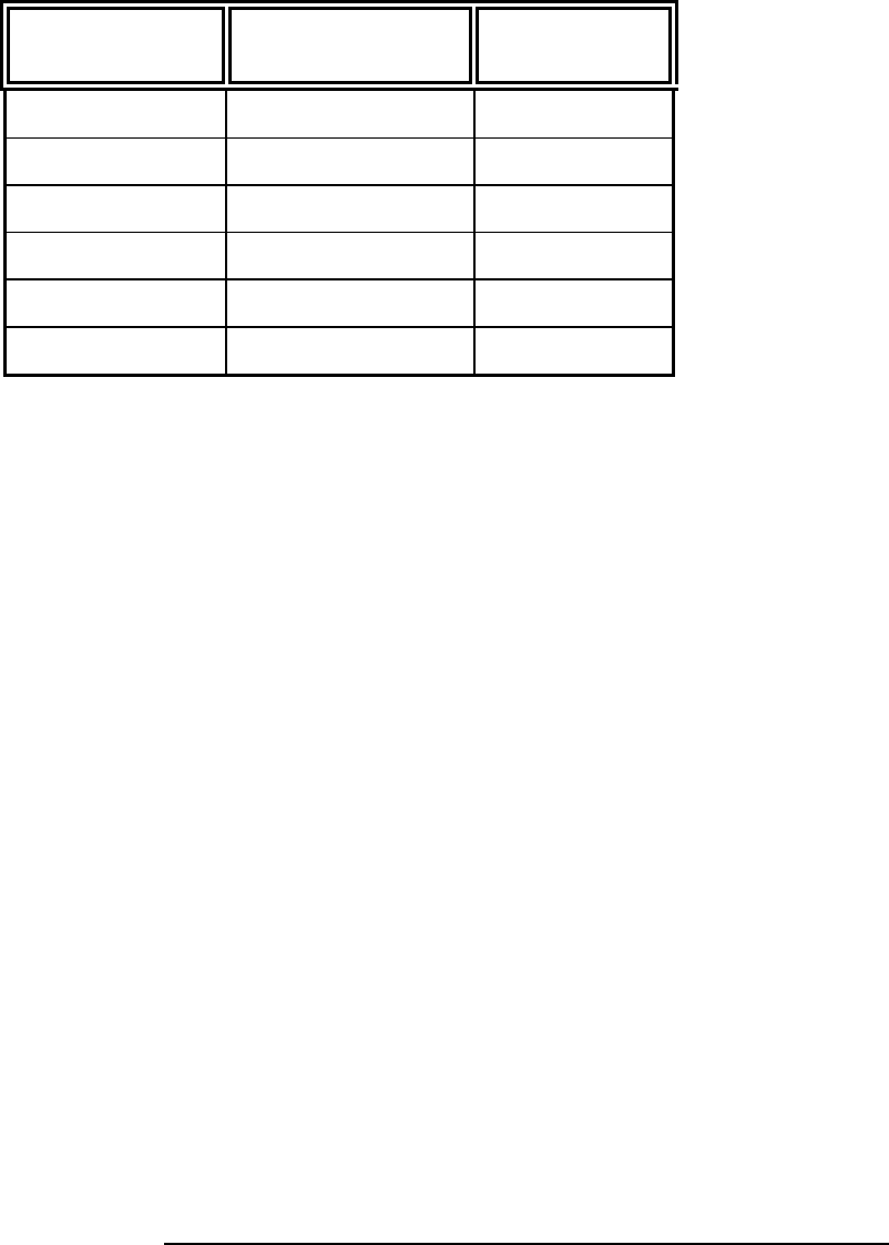
167xx Analyzer 169xx Analyzer File name for
State/Timing Analysis Description
16715/6/7/9 or
1674X or
16750/1/2
1680/90,
16750/1/2,
1691x
CP210_1 *2 card state
analysis
16715/6/7/9 or
1674X or
16750/1/2
1680/90,
16750/1/2,
1691x
CP210_2 *2 card timing
16715/6/7/9 or
1674X or
16750/1/2
1680/90,
16750/1/2,
1691x
CP210_3 1 card eyefinder
config
16753/4/5/6 16753/4/5/6,
1691x CP210_4 1 card eyescan
config
10
The following explains how to connect the logic analyzer to the FS2010
for either state or timing analysis:
1. Connect the logic analyzer PODs 3 adapter cables, either the
E5378A or E5385A depending on the logic analyzer cards used.
2. Plug the Adapter cables into the probe as shown in the table
below.
167XX/1655X PCI-X Analysis Probe
connector Comment
Master POD 1 J2 odd J CLK
Master POD 2 J2 even
Master POD 3 J3 odd
Master POD 4 J3 even
Expander POD 1 J4 odd optional 64 bit
Expander POD 2 J4 odd optional 64 bit
The card edge connector of the FS2010 module can accommodate one
64 or 32 bit 3.3V PCI-X add-in card. To install simply align the module
with the connector and gently push the module in until it is seated in the
connector. There is sufficient clearance for the add-in card front plate.
The FS2010/PCI-X add-in card combination can then be installed in any
slot of the PCI-X Local bus.
When removing the PCI-X add-in card from the card edge extender
connector grasp the FS2010 with one hand and the PCI-X add-in card
with the other. Gently rock the PCI-X add-in card until it is free from the
connector.
The nature of an extender card is that it extends the etch length of the
bus. Due to the sensitivity of some PCI-X designs, extending the etch
length can interfere with the PCI-X add-in card operation. Operation of
the PCI-X add-in card when installed in the card edge extender
connector is not guaranteed.
Connecting the
167xx Agilent logic
analyzer to the
FS2010
How to install a PCI-X
add-in card into the
FS2010
System operation with
the PCI-X add-in card
11
To install the FS2010 software, insert the diskette labeled 16700/702
Installation disk for the FS2010 into the Agilent 16700 diskette drive.
From the SYSTEM ADMINISTRATION TOOLS select INSTALL under
SOFTWARE. From the SOFTWARE INSTALL screen select the
FLEXIBLE DISK and APPLY. Once the title appears select it and then
select INSTALL.
This procedure does not need to be repeated. It only needs to be
done the first time the PCI-X Analysis Probe is used.
When this has completed, load the appropriate configuration file from the
/configs/FuturePlus/FS2010 directory. Refer to the table on the following
pages for a list of analyzers and corresponding configuration files.
The FS2010 product is a licensed product, which is locked to a single
Agilent 1670x frame. Complete instructions for licensing this software
are detailed on the Entitlement Certificate that is enclosed with this
product.
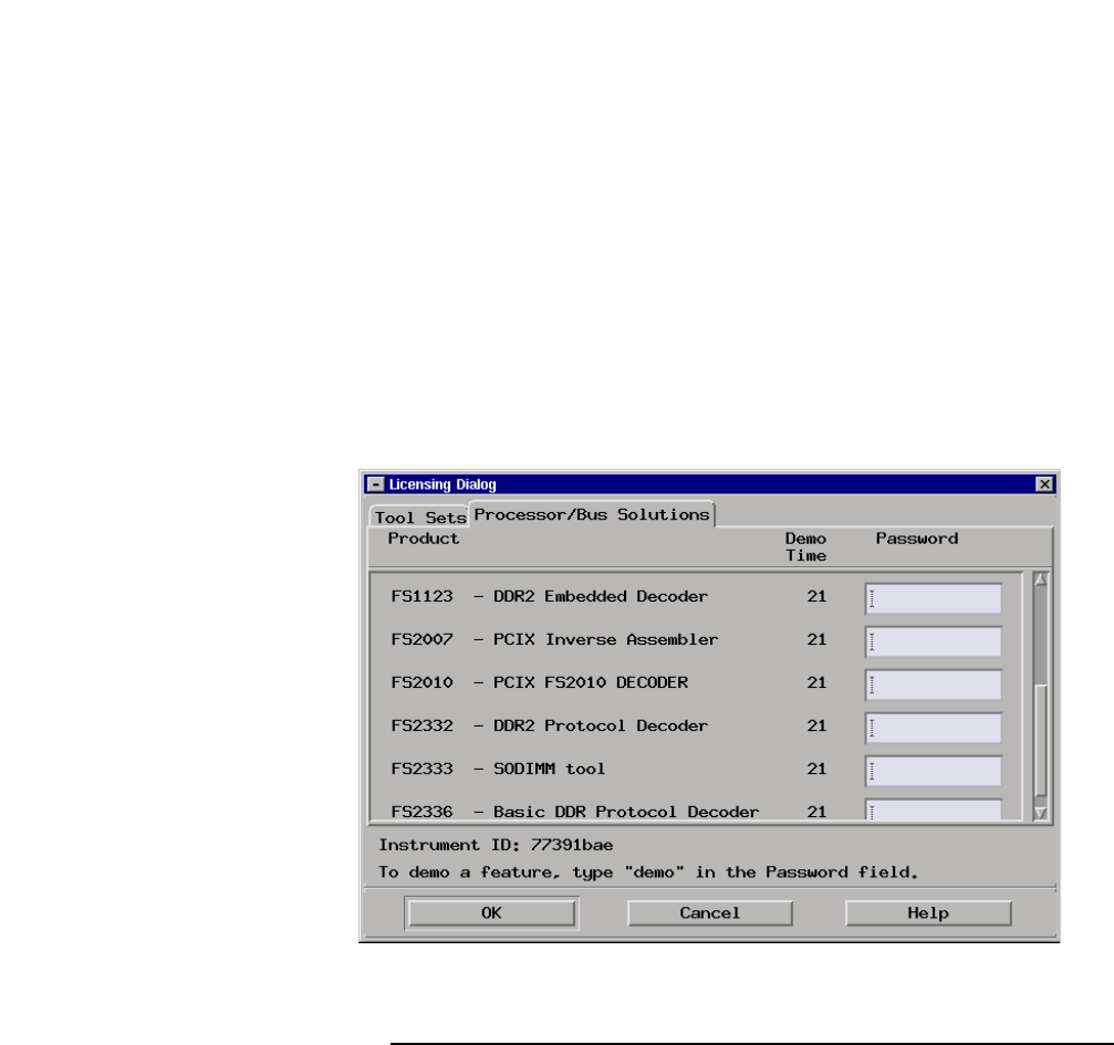
The licensing area for the 1670x mainframe is found under System
Administration. Once you are at the licensing area choose the
Processor/Bus Solutions tab, in here you will find the PCIX inverse
assembler listed. Type your password in the space provided to enable
the use of the inverse assembler. A demo period is provided by typing
the word demo into the password space next to the product name.
The following picture shows the licensing area after pressing the
licensing button on the previous screen. This is where you would enter
the password you will receive after following the instructions on the SW
License Entitlement Certificate.
Setting up the 167xx
Analyzer
167xx
Licensing

12
The 1680/90/900 Analyzer is a PC based application that requires a PC
running Windows OS with the Agilent logic analyzer software installed or
a 16900 frame.
Before installing the protocol decoder for the PCI-X protocol on a PC you
must install the Agilent logic analyzer software. Once the Agilent logic
analyzer software is installed, you can install the FS2010 protocol
decoder by placing the CD-ROM disk into the CD-ROM drive of the
target computer or Analyzer and executing the .exe setup program that
is contained on the disk. The .exe setup file can be executed from within
the File Explorer PC Utility. You must navigate to the .exe file on the CD-
ROM disk and then double click the .exe file name from within the File
Explorer navigation panel.
The installation procedure does not need to be repeated. It only
needs to be done the first time the Analysis Probe Adapter is used.
The PCI Inverse Assembler is a licensed product that is locked to a
single hard drive. The licensing process is performed by Agilent. There
are instructions on this process on the 16900 SW Entitlement certificate
provided with this product.
When the software has been licensed you should be ready to load a
configuration file. You can access the configuration files by clicking on
the folder that was placed on the desktop. When you click on the folder
it should open up to display all the configuration files to choose from. If
you put your mouse cursor on the name of the file a description will
appear telling you what the setup consists of, once you choose the
configuration file that is appropriate for your configuration the 16900
operating system should execute. The protocol decoder automatically
loads when the configuration file is loaded. If the decoder does not load,
you may load it by selecting tools from the menu bar at the top of the
screen and select the decoder from the list.
For a diagram on logic analyzer cable attachment to the probe click the
properties button on the General Purpose Probe icon from the overview
tab. When you click the Properties button another window will open
showing what pods are attached to each cable. If you select one of the
entries from the list in the window another window will open up showing
the signal name on each pin of the connector the cables are attached to.
Refer to the table on page 9 for a list of analyzers and corresponding
configuration files.
Setting up the
1680/90/900 Analyzer
1680/90/900
Licensing
Loading 1680/90/900
configuration files
Connecting the
1680/90/9xx Agilent
logic analyzer to the
FS2010

13
Data that is saved on a 167xx analyzer in fast binary format, or 16900
analyzer data saved as a *.ala file, can be imported into the 1680/90/900
environment for analysis. You can do offline analysis on a PC if you
have the 1680/90/900 operating system installed on the PC, if you need
this software please contact Agilent.
Offline analysis allows a user to be able to analyze a trace offline at a PC
so it frees up the analyzer for another person to use the analyzer to
capture data.
If you have already used the license that was included with your package
on a 1680/90/900 analyzer and would like to have the offline analysis
feature on a PC you may buy additional licenses, please contact
FuturePlus sales department.
In order to view decoded data offline, after installing the 1680/90/900
operating system on a PC, you must install the FuturePlus software.
Please follow the installation instructions for “Setting up 1680/90/900
analyzer”. Once the FuturePlus software has been installed and
licensed follow these steps to import the data and view it.
From the desktop, double click on the Agilent logic analyzer icon. When
the application comes up there will be a series of questions, answer the
first question asking which startup option to use, select Continue Offline.
On the analyzer type question, select Cancel. When the application
comes all the way up you should have a blank screen with a menu bar
and tool bar at the top.
For data from a 1680/90/900 analyzer, open the .ala file using the File,
Open menu selections and browse to the desired .ala file.
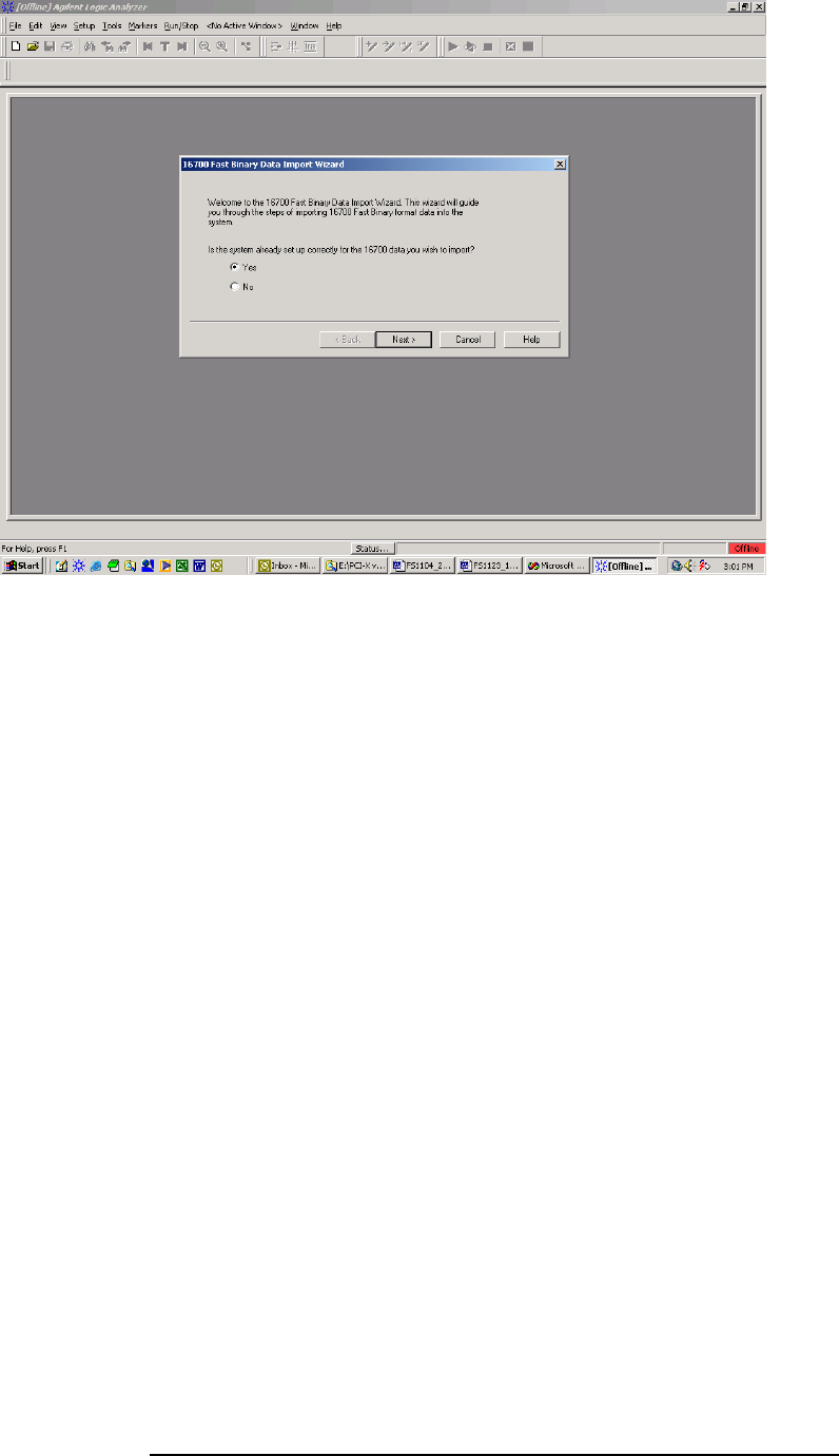
For data from a 16700, choose File -> Import from the menu bar, after
selecting import select “yes” when it asks if the system is ready to import
16700 data.
Offline Analysis
14
After clicking “next” you must browse for the fast binary data file you
want to import. Once you have located the file and clicked start import,
the data should appear in the listing.
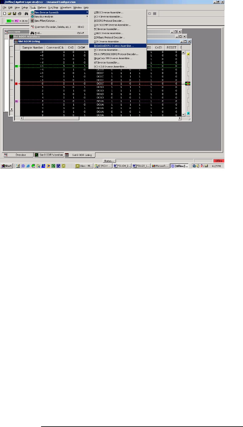
After the data has been imported you must load the protocol decoder
before you will see any decoding. To load the decoder select Tools from
the menu bar, when the drop down menu appears select Inverse
Assembler, then choose the name of the decoder for your particular
product. The figure below is a general picture; please choose the
appropriate decoder for the trace you are working with.
15
After the decoder has loaded, select Preferences if required, from the
overview screen and set the preferences to their correct value in order to
decode the trace properly. This is a general requirement, some
decoders do not have preferences, and if this is the case then no
preference setting is necessary.

16
The FS2010 diskette sets up the format menu as shown in the following
table. This format is the same for both Timing and State Analysis.
Label Clk Inputs Pod 6 Pod 5 Pod 4 Pod 3 Pod 2 Pod 1
ADDR 11,10,9,8,6,5,4,3 11,10,9,6,5,4,3,2 8,7,6,5,3,2,1,0 10:3
ADDR_B 15:0 15:0
STAT K,J,M,L,K 14,13,7,2,1 12,1,0 11,2,1
CLK J
AD_HI 15:0 15:0
AD_LO 11,10,9,8,6,5,4,3 11,10,9,6,5,4,3,2 8,7,6,5,3,2,1,0 10:3
FRAME# 14
IRDY# 2
TRDY# M
STOP# 13
DEVSEL# 1
C/B3_0 L,K 7 12
C/B7_4 K,J 1 0
ACK64# 1
REQ64# 2
PAR 12
PAR_64
REQ# 0
GNT# 10
SERR# 13
PERR# 14
RST# 11
PCIXCAP 0
INTD_A# 15,14 15,14
IDSEL 4
LOCK# 15
M66EN 8
PME# 9
CYCLE M,L,K 14,13,7 12 2,1
TERM CODE M 13 1
The Format Menu
17
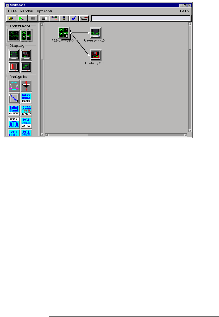
Loading the configuration file will automatically load the PCI-X
Transaction Decode software onto the workspace. If this does not
happen then check to make sure that the PCI-X decode software was
properly installed
The PCI-X
Transaction Decode
Software

18
FS2010 Software and
Timing mode
The FS2010 Decoder should NOT be run when the logic analyzer is
configured in timing mode. This will cause the system to hang.
The ADDR and DATA variables in the FORMAT menu are assigned to
the AD[31:0] signals on the PCI-X bus. The ADDR_B is the AD[63:32]
signals on the PCI-X bus.
The ADDR, ADDR_B and
DATA variables

19
The CYCLE variable is made up of the following signals: TRDY#,
FRAME#, IRDY#, C/BE(3:0), DEVSEL# , and STOP#. This variable has
27 symbols defined that can be used to help make triggering, timing
analysis and pattern filtering easier. The following lists the bit pattern
and the corresponding symbol.
Symbol C/BE(3:0
)
FRAME# IRDY# DEVSEL# TRDY# STOP#
INTACK 0000 0 1 1 1 1
SPECIAL CYCLE 0001 0 1 1 1 1
I/O READ 0010 0 1 1 1 1
I/O WRITE 0011 0 1 1 1 1
RESERVED 0100 0 1 1 1 1
RESERVED1 0101 0 1 1 1 1
MEM RD DWORD 0110 0 1 1 1 1
MEM WRITE 0111 0 1 1 1 1
MEM RD BL 1000 0 1 1 1 1
MEM WR BL 1001 0 1 1 1 1
CONF READ 1010 0 1 1 1 1
CONF WRITE 1011 0 1 1 1 1
SPLIT COMPLETION 1100 0 1 1 1 1
DAC 1101 0 1 1 1 1
MEM RD BLOCK 1110 0 1 1 1 1
MEM WR BLOCK 1111 0 1 1 1 1
IO XACTION 001X 0 1 1 1 1
A
DDR CYCLE XXXX 0 1 1 1 1
DATA XFER XXXX X 0 0 0 1
IDLE XXXX 1 1 X X X
RETRY XXXX X 0 0 1 0
DISC NXT ADB XXXX X 0 0 0 0
DECODE XXXX 0 1 1 1 1
SINGLE DATA DISCON XXXX 0 0 1 0 0
TARGET ABORT XXXX X 1 1 1 0
TARGET RESPONSE
(
WAIT
)
XXXX 0 0 0 1 1
WAIT XXXX 0 0 1 1 1
The CYCLE variable

20
The TERM CODE variable is made up of DEVSEL#, TRDY#, and
STOP#. The following lists the bit pattern and the corresponding symbol.
Symbol DEVSEL# TRDY# STOP#
MASTER ABORT 1 1 1
SPLIT RESPONSE 1 0 1
TARGET ABORT 1 1 0
SINGLE DATA DISC 1 0 0
RETRY 0 1 0
DISC NXT ADB 0 0 0
The hardware layout of the FS2010 made it impossible for the signals to
be connected to the logic analyzer in a logical order. Therefore, bit re-
ordering is done in the configuration file to make the data easier to view.
The bit re-ordering function can be found in the FORMAT menu.
Below is a list of labels that have been re-ordered
ADDR
ADDR_B
STAT
AD_HI
AD_LO
C/B3_0
CYCLE
TERM CODE
Bit Re-ordering

21
State Analysis
This chapter explains how to configure the FS2010 to perform state
analysis on the PCI-X Local Bus. The configuration software sets up the
format specification menu of the logic analyzer for compatibility with the
PCI-X Local Bus. The next chapter explains how to configure the
FS2010 to perform timing analysis.
The FS2010 State/Timing Adapter Probe interface does not require that
a PCI-X add-in card be installed in the FS2010 card edge extender
connector.
Load the logic analyzer configuration file and configure the workspace
for PCI-X analysis.
Configure the trigger menu to acquire PCI-X data. Select RUN and, as
soon as there is activity on the bus, the logic analyzer will begin to
acquire data. The analyzer will continue to acquire data and will display
the data when the analyzer memory is full; the trigger specification is
TRUE or when you select STOP.
The logic analyzer will flash “Slow or Missing Clock” if it does not see the
PCI-X signal CLK toggling.
The logic analyzer will flash “Waiting in level 1” if the trigger specification
has not been met.
If you are analyzing a 32 bit bus, load the configuration file for a 64 bit
bus into a single analyzer card, the upper 64 bit labels will be truncated,
but will work fine.
Acquiring Data
22
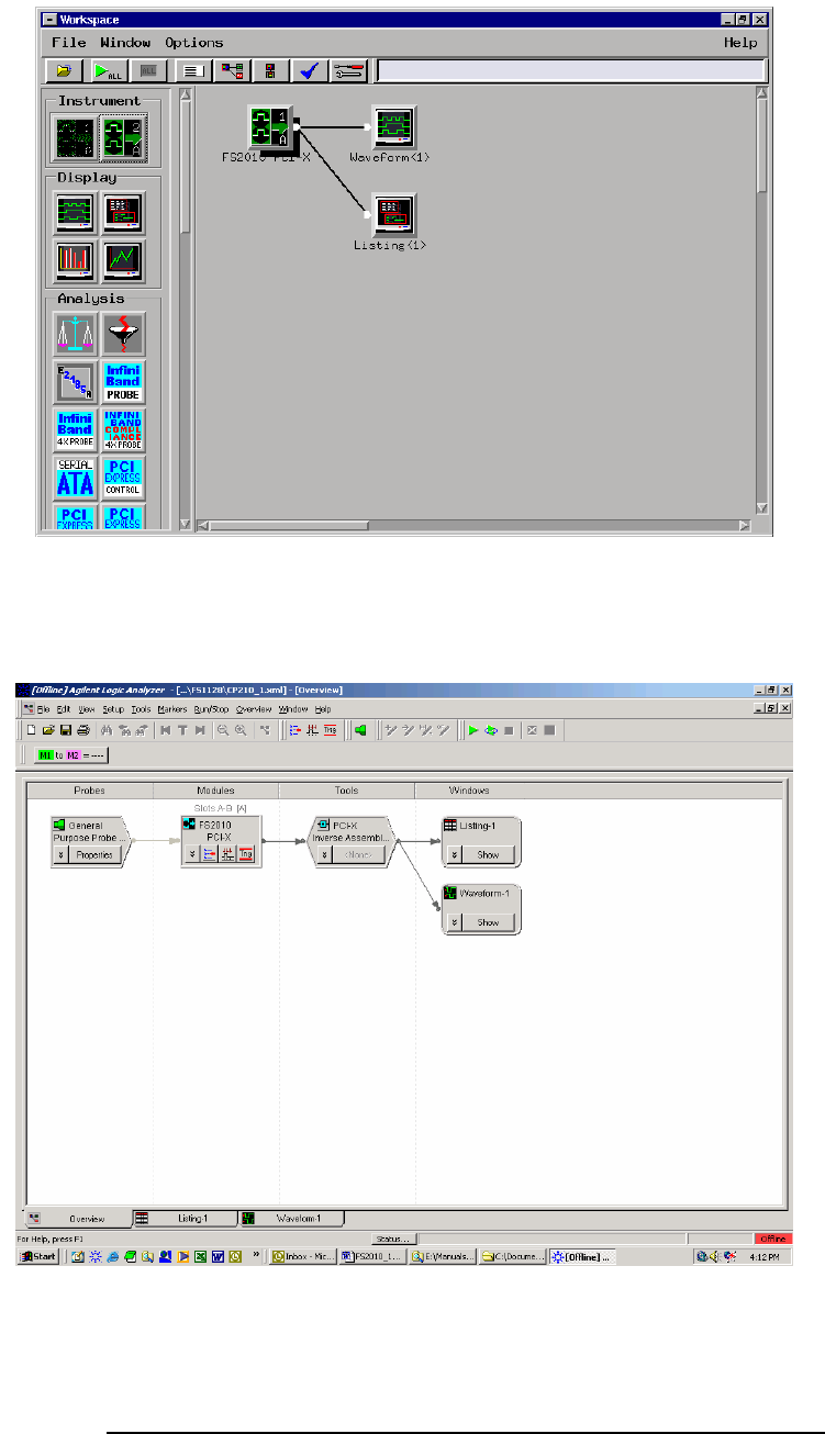
For full analysis, the PCI-X workspace should appear as below.
167xx screenshot
169xx screenshot showing overview
Configuring the
Workspace for PCI-X
Analysis
23
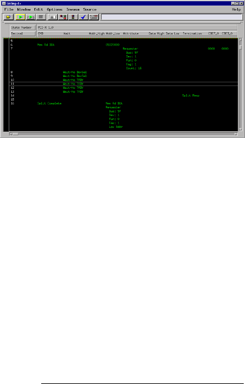
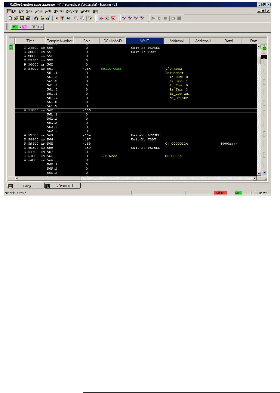
Captured data is as shown in the following figure. The below figure
displays the PCI-X transactor decode on a 167xx frame.
The State Listing
Display
24
T
The above figure shows the listing from the 169xx frame.
25
The FS2010 generates one output column that is sub-divided into the
following sub-columns.
Name Base Description
CMD TEXT The command type displayed in HEX
Wait The type of wait state
ADDR_H TEXT The address as it appears during a 64 bit
address transfer (as defined by a DAC)
ADDR_L HEX The address as it appears on the lower AD
lines (AD[31:0]). This HEX value is
incremented during burst transactions
Data_H TEXT The upper 32 bit AD lines representing data
Data_L TEXT The lower 32 bit AD lines representing data
Termination TEXT Termination type
CBE_H HEX Data byte enables for the upper 32 bit AD
lines (AD[63:32]).
CBE_L HEX Data byte enables for the lower 32 bit AD
lines (AD[31:0]).
The FS2010 Decode Software will perform the following functions:
♦ Decode all PCI-X command and cycle types
♦ Decode Attribute and Split Address fields for easy reading
♦ Color code the data and attribute to match the transaction type
(command). The colors used by the software are as follows:
♦ Memory: Green
♦ Split Completions are colored according to the original request
command ID.
♦ I/O transactions: Yellow
♦ Configuration transactions: Blue
♦ Interrupt Acknowledge, Special Cycle transactions and the DAC
cycle: Purple
♦ Idle: White
♦ Wait cycles: colored in accordance with the rest of the
transaction
♦ Match the Request to the Response by printing the corresponding
address aligned with the data on a Split Response. In addition the
original command will be printed with the Split Response to indicate
what command was originally requested
Functionality of the
FS2010 Transaction
Decode Software

26
Timing Analysis
Since the FS2010 interface does not buffer the PCI-X bus, it introduces
negligible skew to the PCI-X Local Bus signals.
Load the logic analyzer configuration file.
If the FS2010 software is installed, load the logic analyzer
configuration file for timing from the logic/configs/FuturePlus/FS2010
directory on the 167xx analyzer. If using the 1680/90/900 double
click the folder that was placed on the desktop during installation and
choose the appropriate configuration file.
Touch RUN and, as soon as there is activity on the bus, the logic
analyzer will begin to acquire data. The analyzer will continue to acquire
data and will display the data when the analyzer memory is full, the
trigger specification is TRUE or when you touch STOP.
The logic analyzer will flash “Waiting in level 1” if the trigger specification
has not been met.
If you are analyzing a 32 bit bus, load the configuration file for a 64 bit
bus into a single analyzer card, the upper 64 bit labels will be truncated,
but will work fine.
Acquiring Data
27
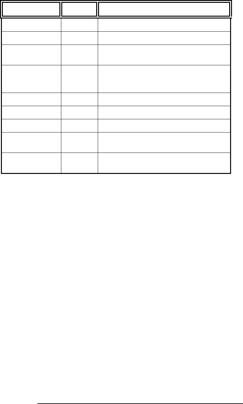
Captured data is displayed as shown in the following figure.
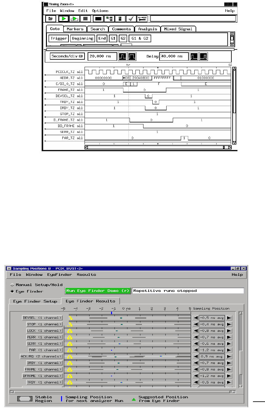
Use of Eye Finder can greatly enhance your timing analysis by helping
find the data valid window of every signal on the bus with respect to the
clock. You can compare the results of Eye Finder to your simulation and
the PCI-X specification to see if your system operates within expected
setup and hold margins. Eye Finder can be found in the setup and hold
area of your logic analysis card FORMAT menu. The configuration file
for Eyefinder, CP201_3 , has clock qualifiers defined to insure that data
is valid during measurements.
EyeScan features are available with 16753/4/5/6 cards that provide
information about signal voltage as well timing windows
The Waveform
Display
Use of
EyeFinder/Eyescan

28
Transaction Viewer
The FS2010 Protocol Decoder version 2.0 or higher is enabled to work
with the FuturePlus Systems Transaction Viewer. The Transaction
Viewer is a powerful tool that allows the user to view PCI-X data
captured with the FS2010 in a graphical environment that presents the
information by Transaction as opposed to State. This tool is fully
integrated with State Listing on the 16900 and allows marker and trigger
settings to be shared between the Protocol Decoder and the Transaction
Viewer.
The Transaction Viewer itself is a separate application that needs to be
downloaded from the FuturePlus Systems website:
www.futureplus.com. The user manual for the Transaction Viewer is also
separate and can be found either on the FuturePlus Systems
Documentation CD on the FuturePlus Systems website.

29
General Information
This chapter provides additional reference information including the
characteristics and signal connections for the FS2010 module.
The following operating characteristics are not specifications, but are
typical operating characteristics for the FS2010 module.
32 or 64 bit PCI-X Local bus universal connector pinout. All PCI-X local
bus ground pins of the universal board pinout are connected to the
ground plane of the FS2010 module.
The FS2010 extender card connector is a 3.3V, 64 bit connector that
accepts either 3.3V or universal 32 or 64 bit long or short card form
factor. All of the signals from the PCI-X bus are routed to the card edge
extender connector.
The PCI-X Local Bus Specification Revision 1.0
The FS2010 State/Timing Adapter Probe logic contains no active
components. The PCI-X add-in card installed in the FS2010 can draw
power from the +/-12V, 3.3V and the 5V pins of the target as if it were
installed without the FS2010.
Agilent 16715/6/7/9, 1674X, or 16750/1/2, 16953/4/5/6 installed in the
16700A or 16700B mainframe. Agilent 1680/90/900, 16953/4/5/6, 1691x,
1695x logic analyzers.
The State/Timing Adapter Probe interface uses 4 cable headers for 32
bit analysis and 6 for 64 bit analysis.
0 to 133Mhz
Characteristics
State/Timing Adapter
Probe Interface
Compatibility
Card Edge Extender
Connector
Standards Supported
Power Requirements
Logic Analyzer Required
Number of Probes Used
Minimum Clock Period
(State)

30
Due to the FS2010 being an interposer all signals are extended 1.2 in. in
length, consisting of 57 ohm single-ended impedance etch.
All PCI-X Local Bus operations are supported by the hardware and the
inverse assembler.
Operating:0 to 55 degrees C (+32 to +131 degrees F)
Non operating:-40 to +75 degrees C (-40 to +167 degrees F)
Operating: 4,6000m (15,000 ft)
Non operating: 15,3000m (50,000 ft)
Up to 90% non-condensing. Avoid sudden, extreme temperature
changes which would cause condensation on the FS2010 module.
There are no automatic performance tests or adjustments for the
FS2010 module. If a failure is suspected in the FS2010 module contact
the factory or your FuturePlus Systems authorized distributor.
The repair strategy for the FS2010 is module replacement. However, if
parts of the FS2010 module are damaged or lost contact the factory for a
list of replacement parts.
The FS2010 contains 3 Samtec connectors which the adapter cables
connect to. Each adapter cable contains 2 connectors to connect to the
Agilent logic analyzer.
The FS2010 module monitors signals for both state and timing analysis.
The following tables list the PCI-X Local Bus signals on the 6 cables.
Etch length
Operations
Environmental
Temperature
Altitude
Humidity
Testing and
Troubleshooting
Servicing
Signal Connections
The State/Timing
Adapter Probe interface
pinout

31
J2 Signal Connector
Signal
Name/Logical
Signal name
Logic Analyzer
channel number SAMTEC
Pin number SAMTEC
Pin number Logic Analyzer
channel number
Signal
name/Logical
Signal Name
Ground 1 2 Ground
NC 3 4 NC
Ground 5 6 Ground
PCIXCAP Odd D0 7 8 Even D0 AD16
Ground 9 10 Ground
DEVSEL# Odd D1 11 12 Even D1 AD18
Ground 13 14 Ground
IRDY# Odd D2 15 16 Even D2 AD20
Ground 17 18 Ground
AD17 Odd D3 19 20 Even D3 AD22
Ground 21 22 Ground
AD19 Odd D4 23 24 Even D4 IDSEL
Ground 25 26 Ground
AD21 Odd D5 27 28 Even D5 AD24
Ground 29 30 Ground
AD23 Odd D6 31 32 Even D6 AD26
Ground 33 34 Ground
AD25 Odd D7 35 36 Even D7 AD28
Ground 37 38 Ground
AD27 Odd D8 39 40 Even D8 AD30
Ground 41 42 Ground
AD29 Odd D9 43 44 Even D9 PME#
Ground 45 46 Ground
AD31 Odd D10 47 48 Even D10 GNT#
Ground 49 50 Ground
REQ# Odd 11 51 52 Even D11 RESET#
Ground 53 54 Ground
NC Odd D12 55 56 Even D12 NC

32
Signal
Name/Logical
Signal name
Logic Analyzer
channel number SAMTEC
Pin number SAMTEC
Pin number Logic Analyzer
channel number
Signal
name/Logical
Signal Name
Ground 57 58 Ground
NC Odd D13 59 60 Even D13 NC
Ground 61 62 Ground
INTD# Odd D14 63 64 Even D14 INTC#
Ground 65 66 Ground
INTB# Odd D15 67 68 Even D15 INTA#
Ground 69 70 Ground
NC 71 72 NC
Ground 73 74 Ground
NC 75 76 NC
Ground 77 78 Ground
CLK Odd D16P/Odd
CLKN 79 80
Even DP16P/Even
CLKN C/BE3#
Ground 81 82 Ground
Ground Odd DP16N/Odd
CLKN 83 84
Even DP16N/Even
CLKN Ground
Ground 85 86 Ground
Odd External Ref 87 88 Even External Ref
Ground 89 90 Ground
NC 91 92 NC
Ground 93 94 Ground
Ground 95 96 Ground
+5V +5V 97 98 +5V +5V
+5V 99 100 +5V +5V

33
J3 Signal Connections
Signal
Name/Logical
Signal name
Logic Analyzer
channel number SAMTEC
Pin number SAMTEC
Pin number Logic Analyzer
channel number
Signal
name/Logical
Signal Name
Ground 1 2 Ground
NC 3 4 NC
Ground 5 6 Ground
C/BE4# Odd D0 7 8 Even D0 PAR64
Ground 9 10 Ground
ACK64# Odd D1 11 12 Even D1 C/BE5#
Ground 13 14 Ground
AD1 Odd D2 15 16 Even D2 REQ64#
Ground 17 18 Ground
AD3 Odd D3 19 20 Even D3 AD0
Ground 21 22 Ground
AD5 Odd D4 23 24 Even D4 AD2
Ground 25 26 Ground
AD7 Odd D5 27 28 Even D5 AD4
Ground 29 30 Ground
AD8 Odd D6 31 32 Even D6 AD6
Ground 33 34 Ground
NC Odd D7 35 36 Even D7 C/BE0#
Ground 37 38 Ground
M66EN Odd D8 39 40 Even D8 AD9
Ground 41 42 Ground
AD10 Odd D9 43 44 Even D9 AD11
Ground 45 46 Ground
AD12 Odd D10 47 48 Even D10 AD13
Ground 49 50 Ground
AD14 Odd 11 51 52 Even D11 AD15
Ground 53 54 Ground
C/BE1# Odd D12 55 56 Even D12 PAR

34
Signal
Name/Logical
Signal name
Logic Analyzer
channel number SAMTEC
Pin number SAMTEC
Pin number Logic Analyzer
channel number
Signal
name/Logical
Signal Name
Ground 57 58 Ground
SERR# Odd D13 59 60 Even D13 STOP#
Ground 61 62 Ground
PERR# Odd D14 63 64 Even D14 FRAME#
Ground 65 66 Ground
LOCK# Odd D15 67 68 Even D15 NC
Ground 69 70 Ground
NC 71 72 NC
Ground 73 74 Ground
NC 75 76 NC
Ground 77 78 Ground
C/BE2# Odd D16P/Odd
CLKN 79 80
Even DP16P/Even
CLKN TRDY#
Ground 81 82 Ground
Ground Odd DP16N/Odd
CLKN 83 84
Even DP16N/Even
CLKN Ground
Ground 85 86 Ground
Odd External Ref 87 88 Even External Ref
Ground 89 90 Ground
NC 91 92 NC
Ground 93 94 Ground
Ground 95 96 Ground
+5V +5V 97 98 +5V +5V
+5V 99 100 +5V +5V

35
J4 Signal Connections
Signal
Name/Logical
Signal name
Logic Analyzer
channel number SAMTEC
Pin number SAMTEC
Pin number Logic Analyzer
channel number
Signal
name/Logical
Signal Name
Ground 1 2 Ground
NC 3 4 NC
Ground 5 6 Ground
AD33 Odd D0 7 8 Even D0 AD32
Ground 9 10 Ground
AD35 Odd D1 11 12 Even D1 AD34
Ground 13 14 Ground
AD37 Odd D2 15 16 Even D2 AD36
Ground 17 18 Ground
AD39 Odd D3 19 20 Even D3 AD38
Ground 21 22 Ground
AD41 Odd D4 23 24 Even D4 AD40
Ground 25 26 Ground
AD43 Odd D5 27 28 Even D5 AD42
Ground 29 30 Ground
AD45 Odd D6 31 32 Even D6 AD44
Ground 33 34 Ground
AD47 Odd D7 35 36 Even D7 AD46
Ground 37 38 Ground
C/BE4# Odd D8 39 40 Even D8 C/BE5#
Ground 41 42 Ground
AD51 Odd D9 43 44 Even D9 AD50
Ground 45 46 Ground
AD53 Odd D10 47 48 Even D10 AD52
Ground 49 50 Ground
AD55 Odd 11 51 52 Even D11 AD54
Ground 53 54 Ground
AD57 Odd D12 55 56 Even D12 AD56

36
Signal
Name/Logical
Signal name
Logic Analyzer
channel number SAMTEC
Pin number SAMTEC
Pin number Logic Analyzer
channel number
Signal
name/Logical
Signal Name
Ground 57 58 Ground
AD59 Odd D13 59 60 Even D13 AD58
Ground 61 62 Ground
AD61 Odd D14 63 64 Even D14 AD60
Ground 65 66 Ground
AD63 Odd D15 67 68 Even D15 AD62
Ground 69 70 Ground
NC 71 72 NC
Ground 73 74 Ground
NC 75 76 NC
Ground 77 78 Ground
C/BE6# Odd D16P/Odd
CLKN 79 80
Even DP16P/Even
CLKN C/BE7#
Ground 81 82 Ground
Ground Odd DP16N/Odd
CLKN 83 84
Even DP16N/Even
CLKN Ground
Ground 85 86 Ground
Odd External Ref 87 88 Even External Ref
Ground 89 90 Ground
NC 91 92 NC
Ground 93 94 Ground
Ground 95 96 Ground
+5V +5V 97 98 +5V +5V
+5V 99 100 +5V +5V
