Agilent Technologies G3180B Users Manual
G3180B to the manual 0f9a330b-71c6-4850-8640-5645215a1326
2015-02-02
: Agilent-Technologies Agilent-Technologies-G3180B-Users-Manual-413162 agilent-technologies-g3180b-users-manual-413162 agilent-technologies pdf
Open the PDF directly: View PDF ![]() .
.
Page Count: 52

Agilent Technologies
Agilent G3180B
Two-Way Splitter Kit
With Makeup Gas
Installation and Operation
Guide

2 Installation and Operation Guide
Notices
©Agilent Technologies, Inc. 2006
No part of this manual may be reproduced in
any form or by any means (including elec-
tronic storage and retrieval or translation
into a foreign language) without prior agree-
ment and written consent from Agilent
Technologies, Inc. as governed by United
States and international copyright laws.
Manual Part Number
G3180-90120
Supercedes G3180-90110
Edition
First edition, April 2006
Printed in USA
Agilent Technologies, Inc.
2850 Centerville Road
Wilmington, DE 19808-1610 USA
Warranty
The material contained in this
document is provided “as is,” and
is subject to being changed, with-
out notice, in future editions. Fur-
ther, to the maximum extent
permitted by applicable law,
Agilent disclaims all warranties,
either express or implied, with
regard to this manual and any
information contained herein,
including but not limited to the
implied warranties of merchant-
ability and fitness for a particular
purpose. Agilent shall not be
liable for errors or for incidental
or consequential damages in
connection with the furnishing,
use, or performance of this
document or of any information
contained herein. Should Agilent
and the user have a separate
written agreement with warranty
terms covering the material in this
document that conflict with these
terms, the warranty terms in the
separate agreement shall control.
Safety Notices
CAUTION
A CAUTION notice denotes a haz-
ard. It calls attention to an operat-
ing procedure, practice, or the like
that, if not correctly performed or
adhered to, could result in damage
to the product or loss of important
data. Do not proceed beyond a
CAUTION notice until the indicated
conditions are fully understood and
met.
WARNING
A WARNING notice denotes a
hazard. It calls attention to an
operating procedure, practice, or
the like that, if not correctly per-
formed or adhered to, could result
in personal injury or death. Do not
proceed beyond a WARNING
notice until the indicated condi-
tions are fully understood and
met.
Acknowledgement
Microsoft® is a U.S. registered trademark
of Microsoft Corporation.
Installation and Operation Guide 3
In this Guide. . .
This Installation and Operation Guide contains information for installing and
using an effluent splitter on an Agilent 6890 gas chromatograph (GC). The
G3180 splitter is intended for use with capillary columns and uses makeup gas
to maintain adequate flows throughout the system.
1 Introduction
This chapter describes how the splitter works, the GC and software
requirements of the system and the contents of the installation kit.
2 Hardware Installation
See this chapter for a detailed procedure for installing the splitter hardware
and connecting the makeup gas supply.
3 Splitter Configurations
The split ratio (how the column effluent divides between the two detectors) is
governed by two restrictors, which are lengths of deactivated fused silica
tubing. This chapter presents a set of precalculated “typical” configurations. If
desired, you can create a custom configuration to meet specific needs. The
chapter describes a set of software tools, included in the kit, to assist you in
designing such configurations. Finally, installation of the column and
restrictors is covered.
4Operation
This chapter contains a worked-out custom configuration, plus a few special
topics.
4 Installation and Operation Guide
Installation and Operation Guide 5
Contents
1 Introduction
Overview 8
How It Works 9
Details 10
Metal ferrules 10
Microfluidic plate 10
Constant pressure operation 10
Calculation of chromatographic parameters 11
GC Requirements 12
Other Requirements 12
Parts Supplied 13
Part Identification 14
Parts Not Supplied 15
Tools Required 15
2 Hardware Installation
Prepare the GC 18
Install the Column Clips 20
Install the Bracket and Splitter 21
Connect the Makeup Gas Supply 24
To supply the makeup gas froma PCM 24
To supply the makeup gas from an Auxiliary Pressure
controller 24
6 Installation and Operation Guide
3 Splitter Configurations
Typical Configurations 26
Splitting to an MSD 28
Custom Configurations 29
Restrictor id and length 32
Maximum and minimum flows 33
Column outlet pressure 34
Inlet pressure 34
Restrictor and Column Installation 35
Install the column 35
Connect the splitter 35
Disconnect tubing from the splitter 37
4Operation
An Example 40
Column flow 40
Select restrictors 42
Calculate column flow 43
Calculate ECD restrictor flow 44
Calculate MSD restrictor flow 45
Changing Columns Without Venting the MSD 46
Backflushing the Column 47

7
Agilent G3180B Splitter Kit
Installation and Operation Guide
Agilent Technologies
1
Introduction
Overview 8
How It Works 9
Details 10
Metal ferrules 10
Microfluidic plate 10
Constant pressure operation 10
Calculation of chromatographic parameters 11
GC Requirements 12
Other Requirements 12
Parts Supplied 13
Part Identification 14
Parts Not Supplied 15
Tools Required 15
This manual covers the installation and operation of the G3180B effluent
splitter with makeup gas kit on the Agilent 6890 series gas chromatograph
(GC).
8 Installation and Operation Guide
1Introduction
Overview
Splitter installation is done in three steps:
1Hardware installation. This gets the hardware installed and the gas flows
connected.
2Restrictor configuration. You can choose to use a typical, precalculated
configuration or create a custom one using software tools supplied on a CD.
3Restrictor and column installation. Using the results of step 2, cut the
appropriate lengths of the appropriate diameter tubing for the restrictors.
Install the restrictors and the analytical column.
Introduction 1
Installation and Operation Guide 9
How It Works
The splitter divides the effluent from a column between two different
detectors. The detectors can be operating at different pressures, that is, any
mix of the following can be used:
• Atmospheric pressure
FID (flame ionization detector)
TCD (thermal conductivity detector)
NPD (nitrogen phosphorus detector)
ECD (electron capture detector)
FPD (flame photometric detector)
• Below atmospheric pressure
MSD (mass selective detector)
• Above atmospheric pressure
AED (atomic emission detector)
The split ratio is determined by the length and diameter of tubing connecting
the splitter to the detectors. Tubing dimensions may be determined from
Table 2 on page 26 in this manual or from a spreadsheet calculator that is
included for calculating tubing dimensions for special situations.
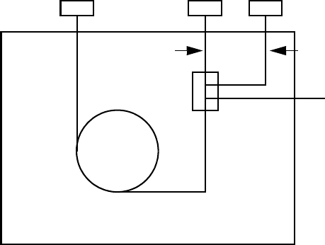
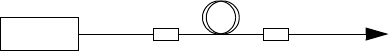
Figure 1 shows the plumbing configuration for the G3180B splitter.
Figure 1 Splitter plumbing
Restrictor 1 Restrictor 2
Constant pressure
makeup gas supply
Column
Splitter
GC oven
Det 1 Det 2Inlet
10 Installation and Operation Guide
1Introduction
The column flow mixes with the makeup flow in the splitter. This mixture then
flows through lengths of uncoated, deactivated, fused-silica tubing to each
detector. These tubes act as flow restrictors. While the flow through each
restrictor changes with oven temperature, the ratio of the two flows at any
temperature is the same.
Details
The G3180B kit addresses several limitations of previous approaches to
splitting column effluent between two detectors:
Metal ferrules
The splitter uses metal column ferrules, which eliminate air leakage into the
sample stream. Unlike polyimide, metal ferrules do not loosen upon thermal
cycling of the oven. They also do not outgas contaminants or shed particles
(like graphite) that can result in chromatographic problems.
Microfluidic plate
The splitting hardware is based on microfluidic plate technology. This allows
very low dead volume connections between the column end and the two
detector restrictor tubes. The thin metal plate has fast thermal response and is
mounted solidly on the oven wall for ease of use. The interior plate surfaces
are deactivated to prevent adsorption by active compounds.
Constant pressure operation
The splitter uses a source of makeup gas supplied by electronic pneumatics
control (EPC). This maintains the splitter at a known and constant pressure.
Constant pressure allows easier splitting to vacuum detectors like the MSD. It
simplifies choice of splitter parameters, allowing all aspects of the
chromatographic setup to be calculated. Constant pressure makeup allows the
column to be run in constant flow mode while still maintaining a constant
split ratio between two detectors of different operating pressures such as the
FPD and the MSD. Because the EPC pressure can be time programmed, useful
operations like backflushing unwanted heavy materials from the column and
changing columns in MSD systems without venting are possible.
Introduction 1
Installation and Operation Guide 11
Calculation of chromatographic parameters
Because the pressure at the split point is known and constant, the
chromatographic parameters can be calculated before setup. This is especially
useful with GC/MSD setups, where there are limitations on the flow rates of
carrier gas allowed into the MSD. If a method that was originally developed on
an MSD is converted to a splitter setup, a new inlet pressure can be calculated
to produce retention times very similar to the original method.
12 Installation and Operation Guide
1Introduction
GC Requirements
The splitter mounts in an Agilent 6890 series GC.
The splitter requires an electronically controlled pressure source such as the
Three Channel Pressure controller (6890 option 205, 301, or 308) or a
Pneumatics Control Module (PCM).
Other Requirements
The calculator requires Microsof®t Excel 97 (or later), which is not supplied
with this kit.

Introduction 1
Installation and Operation Guide 13
Parts Supplied
The G3180B kit contains the following parts (Table 1).
Table 1 Parts supplied
Part number Description Quantity
0100-0124 Union, stainless steel, 1/16-inch tubing 2
0100-0241 Union, stainless steel, 1/8 to 1/16-inch reducing 1
G1580-00130 Valve box blanking plate 1
G1530-01340 Capillary column spring clips 4
0515-0374 Screw, M3 × 10 mm 7
G2855-60140 Oven bracket assembly 1
G2855-60560 T-screw oven bracket retainer 2
G2855-80022 Manual and calculator CD 1
G3180-90120 Manual, G3180B
0100-2354 Tubing, stainless steel, 1/16-inch od × 0.01-inch id, 1 m 1
G3180-61500 Compact splitter with makeup gas assembly 1
G2855-60150 Supplies and spares kit 1
14 Installation and Operation Guide
1Introduction
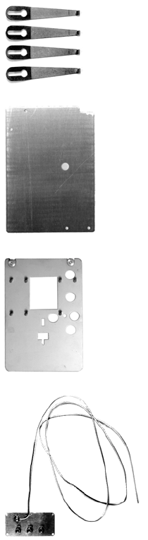
Part Identification
Most of the kit parts are easily recognized. The unique ones are identified in
Figure 2.
Figure 2 Part identification
Capillary column
spring clips
Valve box
Oven bracket
Compact splitter
blanking plate
assembly
with makeup gas
assembly
This assembly is shipped in a
plastic bag to keep contaminants
out of the tubing and the fittings.
Do not open the bag until you are
ready to install the splitter.
Introduction 1
Installation and Operation Guide 15
Parts Not Supplied
Brown-dot frit (19231-60610)
Tools Required
Side cutter, large
Open-end wrenches
16 Installation and Operation Guide
1Introduction

17
Agilent G3180B Splitter Kit
Installation and Operation Guide
Agilent Technologies
2
Hardware Installation
Prepare the GC 18
Install the Column Clips 20
Install the Bracket and Splitter 21
Connect the Makeup Gas Supply 24
This chapter describes the procedure for installing the splitter hardware and
connecting the makeup gas supply.
18 Installation and Operation Guide
2Hardware Installation
Prepare the GC
1Raise the GC top cover to expose the oven top.
2Remove the valve box cutout using a side cutter (Figure 3).
WARNING Turn the power off and disconnect the power cord before proceeding.
Figure 3 Remove the valve box cutout
Cut tabs
around edges
and remove
Hardware Installation 2
Installation and Operation Guide 19
3This exposes a layer of soft insulation. Remove it to expose the hard oven
insulation. Remove the precut insulation piece at the location shown in
Figure 4.
4Replace the soft insulation. Install the valve box blanking plate, using one
screw at the front and one at the rear to secure it. See Figure 5.
Figure 4 Remove the insulation cutout
Figure 5 Install valve box blanking plate
Remove
this
cutout
Two screws

Hardware Installation 2
Installation and Operation Guide 21
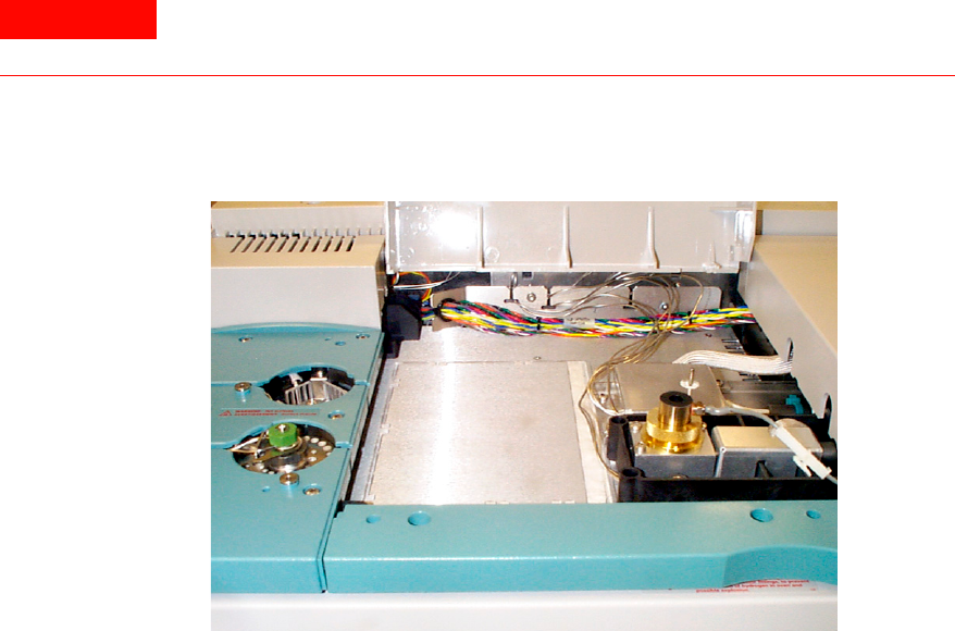
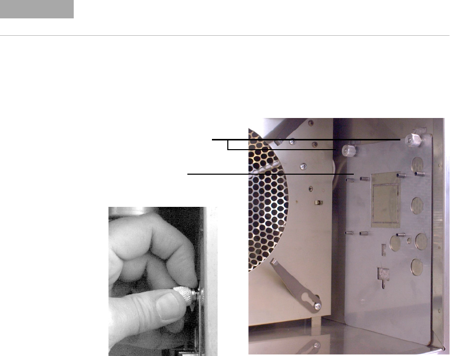
Install the Bracket and Splitter
The splitter is usually installed on the right side of the oven.
1Place the bracket against the side of the oven. The two notches should be up
and the standoffs should face the center of the oven.
2Use two T-shaped thumbscrews to fasten the bracket to the T-slots in the
oven wall (Figure 7).
NOTE The body of the splitter may be discolored as a result of the deactivation process. This is
not a defect.
Figure 7 Installing the bracket
Thumbscrews
Detail
Bracket
22 Installation and Operation Guide
2Hardware Installation
3Open the plastic bag and remove the splitter assembly. Install a plastic cap
on the end of the makeup gas tubing. Place small pieces of tape over the
open end of the fittings.
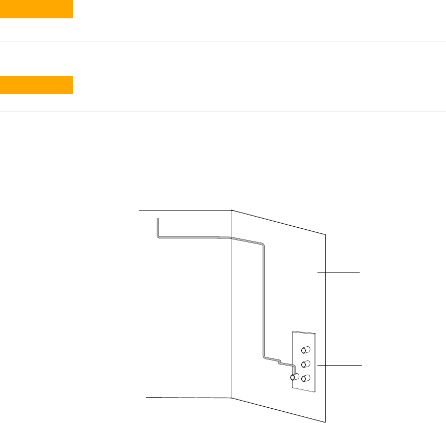
4Prebend the tubing according to Figure 8. This will make splitter
installation much easier.
5Push the end of the makeup gas tubing up through the top oven wall so that
the end of the tubing comes out in the hole of the valve box blanking plate.
CAUTION Use extreme care to prevent any fragments of insulation or other material from
entering the makeup gas tubing or the fittings on the splitter assembly. Such materials
could block the internal passages in the splitter or the bore of the capillary restrictors.
CAUTION In the following steps, bend the tubing over an object such as your thumb to avoid
kinks.
Figure 8 Prebending the splitter tubing
45 mm
140 mm
60 mm
Dimensions are approximate
195 mm
Splitter assembly
Oven side wall
Up through hole
in oven top and
blanking plate
All bends are 90°
Hardware Installation 2
Installation and Operation Guide 23
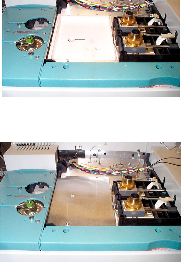
6Route the prebent tubing against the oven wall and top to keep it clean for
future maintenance. It should be behind the back detector location.
7Screw the splitter assembly to the bracket (three screws). See Figure 9.
Figure 9 Installing the splitter assembly
Makeup gas tubing
Splitter assembly
Mounting screw
Mounting screws
Ferrule release hole
24 Installation and Operation Guide
2Hardware Installation
Connect the Makeup Gas Supply
Connect the makeup gas source to the PCM or Auxiliary Pressure controller.
To supply the makeup gas froma PCM
1Connect the tubing from the PCM to the 1 meter length of stainless steel
tubing from the kit with a union.
2Connect the free end of the stainless steel tubing to the tubing from the
splitter assembly with a union. See Figure 10.
To supply the makeup gas from an Auxiliary Pressure controller
1Install the brown-dot frit (part no. 19231-60610) in the output channel. See
your GC manual for details.
2Connect the tubing from the Auxiliary Pressure controller to the tubing
from the splitter assembly with the 1/8 to 1/16-inch stainless steel reducing
union.
This completes the hardware installation.
Figure 10 Plumbing a PCM makeup supply
PCM
Union Union
To splitter
Stainless
steel
tubing

25
Agilent G3180B Splitter Kit
Installation and Operation Guide
Agilent Technologies
3
Splitter Configurations
Typical Configurations 26
Splitting to an MSD 28
Custom Configurations 29
Restrictor id and length 32
Maximum and minimum flows 33
Column outlet pressure 34
Inlet pressure 34
Restrictor and Column Installation 35
Install the column 35
Connect the splitter 35
Disconnect tubing from the splitter 37
The combination of restrictor diameters and lengths determines how the
column effluent is divided (the split ratio) between the two detectors. There
are two approaches to setting up a splitter method.
•Use a typical configuration. A set of eight configurations is discussed
beginning on the next page. They apply to a variety of detector
combinations and split ratios. All of the flows have been calculated.
•Create a custom configuration. If the typical configurations do not meet
your needs, you can create one that does. The CD shipped with the splitter
kit provides tools for the necessary calculations.
We suggest examining the typical configurations first, since they cover a wide
variety of splitter applications and require no calculations.

26 Installation and Operation Guide
3Splitter Configurations
Typical Configurations
The important parameters when setting up a splitter are the lengths and
diameters of the restrictor tubes that go to the two detectors. The dimensions
of the restrictors are chosen to give the desired split ratio, flow to the detector,
and to minimize peak broadening.
The splitter restrictors are chosen based on:
•The range of column flows that will be used with the method
•The operating pressure of the two detectors
•The flow rate requirements of the two detectors
Table 2 lists typical splitting configurations. Table 3 shows the resulting gas
flows. All calculations assume helium as the carrier gas.
Table 2 Restrictor configurations
Configuration Det 1 Det 2 Split ratio,
Det 2/Det 1
Diam R1,
mm id
Length R1,
m
Diam R2,
mm id
Length R2,
m
1atm* atm 1 0.25 0.544 0.25 0.544
2atm atm 5 0.18 0.418 0.25 0.311
3atm MSD,D** 1 0.18 1.060 0.18 2.890
4atm MSD, T*** 1 0.18 0.530 0.18 1.440
5atm MSD, D 2 0.18 2.130 0.18 2.890
6atm MSD, T 2 0.18 1.064 0.18 1.443
7atm MSD, D 5 0.10 0.507 0.18 2.890
8atm MSD, T 5 0.18 2.660 0.18 1.443
* atm Atmospheric pressure detectors such as FID, TCD, ECD, FPD and NPD
** MSD, D MSD with diffusion pump or standard turbo pump (2 mL/min flow capability)
*** MSD, T MSD with performance turbo pump (4 mL/min flow capability); makeup pressure supply is set to 3.8 psig

Splitter Configurations 3
Installation and Operation Guide 27
To use the tables, select the configuration you wish to set up. For example,
Configuration 1 splits column effluent equally between two atmospheric
pressure detectors (FID, TCD, ECD, FPD, and NPD). To plumb this system,
0.544-m lengths of 0.25-mm id uncoated deactivated fused silica tubing are
connected as restrictors from the splitter to the two detectors.
The makeup supply (either Aux EPC or PCM module) is set to 3.8 psig. This
will add sufficient makeup flow to the column flow to maintain the splitter
(and thus the column outlet) at 3.8 psi. Column flow can be varied from 0 to a
maximum flow which is determined by the upper temperature of the GC oven
program.
If Configuration 1 is used with a method that programs to 200 °C using helium,
the flow through each restrictor at 200 °C will be 7.3 mL/min. The total flow
will be 14.6 mL/min. The maximum column flow should be equal to the total
flow minus about 1 mL/min to ensure that there is some flow for the makeup
supply to regulate with.
The column flow at 200 °C should be no more than 13.6 mL/min. This becomes
important when the column is run in constant flow mode. If constant flow
mode is used with Configuration 1 and the method programmed to 400 °C, the
column flow should not exceed 6.8 mL/min ([3.9 + 3.9] –1).
Table 3 Splitter flows
40 °C 200 °C 300 °C 400 °C
Configuration Flow R1,
mL/min
Flow R2,
mL/min
Flow R1,
mL/min
Flow R2,
mL/min
Flow R1,
mL/min
Flow R2,
mL/min
Flow R1,
mL/min
Flow R2,
mL/min
114.7 14.7 7.3 7.3 5.2 5.2 3.9 3.9
25.1 25.6 2.5 12.7 1.8 9.1 1.4 6.8
322110.70.70.540.54
444221.41.41.11.1
51 2 0.5 1 0.36 0.72 0.27 0.54
624120.711.40.531.06
70.4 2 0.2 1 0.14 0.7 0.1 0.5
80.8 4 0.4 2 0.28 1.4 0.21 1.1
28 Installation and Operation Guide
3Splitter Configurations
For constant pressure methods, first find the maximum flow as above. Use the
GC, ChemStation, Flow Calculator Software or the Method Translation
Software to find the inlet pressure that gives the maximum flow at the upper
temperature of the method (make sure the column outlet pressure is set to
3.8 psig for the calculation).
For example, if a 30 m × 0.32-mm id column is used with Configuration 1, using
helium carrier and programming to 300 °C, the pressure that gives a flow of
9.4 mL/min ([5.2 + 5.2] – 1 = 9.4) is 56.3 psig. This is the maximum pressure at
which the inlet should be set. The inlet should not be set at or below 3.8 psig.
If you decide to use a typical configuration, note the restrictor dimensions
from Table 2 and proceed to “Restrictor and Column Installation" on page 35.
Splitting to an MSD
Note that the maximum column flows for an MSD are quite low. This limit is
imposed by the rating of the turbo or diffusion pump. Configurations with
split ratios greater than 1 can be used but peak broadening and/or tailing
should be expected. They are shown in the configuration tables more as a
caution than as a recommendation.
In practice, the column flow can be set to within 0.5 mL/min of the total flow
if necessary. For example, the 1:1 split to an MSD with a performance turbo
pump running a method programmed to 300 °C should have a column flow of
no more than 2.3 mL/min ([1.4 + 1.4] – 0.5) at 300 °C.
Split ratios to the MSD greater than 1 are very limited due to these flow
considerations and should be avoided if possible.
Splitter Configurations 3
Installation and Operation Guide 29
Custom Configurations
The CD supplied with this kit contains three software tools:
Effluent Splitter Calculator (with Makeup) Calculates dimensions (length and
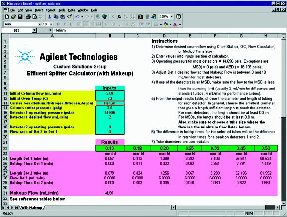
inside diameter) of restrictors to obtain a desired split ratio (Figure 11).
Figure 11 Effluent Splitter Calculator

Splitter Configurations 3
Installation and Operation Guide 31
Column Pressure/Flow Calculator Calculates flows and pressures for a given
set of column (or restrictor) dimensions (Figure 13).
These tools allow you to perform all the calculations needed to create a
custom splitter configuration. We recommend that you load the CD software
into your PC.
1Insert the CD into the drive and click the Start icon in the bottom left of the
screen. Select Run and type X:\ Setup, where X is the letter assigned to the
CD drive.
2Click Start, then select Programs and the program you wish to run.
Figure 13 Column Flow/Pressure Calculator
32 Installation and Operation Guide
3Splitter Configurations
Restrictor id and length
1Run the Effluent Splitter Calculator and enter the following information.
The calculator provides a list of possible restrictors.
•Column flow. Use the ChemStation, GC, Flow Calculator, or Method
Translation Software to determine the column flow in mL/min (with the
column outlet at 3.8 psig) at the initial oven temperature.
•Initial oven temperature. This is the temperature setpoint for an
isothermal method or the initial temperature for a programmed method.
•Carrier gas type. Enter Helium, Hydrogen, Nitrogen, or Argon.
•Detectors 1 and 2 operating pressure (psia). The operating pressure
must be in absolute units. Most detectors (FID, TCD, ECD, NPD, and
FPD) operate at atmospheric pressure (14.696 psia). Exceptions are the
MSD (0 psia) and AED (16.196 psia).
•Flow Ratio of Detector 2 to Detector 1. This is the desired split ratio
between the two detectors. Usually this number is 1, meaning the
effluent divides equally between the detectors. This can be adjusted to
higher values, but should normally not exceed five.
•Splitter (column outlet) pressure (psig). This is the desired pressure at
which the splitter (and thus the end of the column) will operate. It can be
set between 2 and 4 psig, but is usually set to 3.8 psig. This number can
be varied to obtain an acceptable combination of restrictors that will
have sufficient flow velocity to give good peak shapes.
2Choose the id tubing that gives a length closest to (and at least) 0.3 m for
most detectors and 0.8 m for MSDs. The green fields with tubing diameters
in mm can be edited if you have other sizes of deactivated tubing available.

Splitter Configurations 3
Installation and Operation Guide 33
Maximum and minimum flows
The maximum suggested flow for MSDs depends on the vacuum pump used.
For diffusion pump and standard turbo systems, the flow should not exceed
2 mL/min. For performance turbo systems, the flow should not exceed
4 mL/min. These flow limits restrict the column flows and split ratios that can
be used with MSDs.
Make sure that the flow through each restrictor tube is at least equal to the
suggested minimum flow in Table 4. Restrictors that fail this test will still
work, but peak broadening and/or tailing may result.
1The makeup flow is listed in cell B 31 of the effluent splitter calculator. You
should have at least 0.5 mL/min for stable pressure regulation. Note that
this value will decrease as the oven temperature programs up.
2Use the Column Pressure/Flow Calculator to determine the flow through each
restrictor at the maximum oven temperature of the method, add them and
subtract the calculated column flow at that temperature. This value should
be greater than 0.5 mL/min.
Table 4 Suggested minimum restrictor flows
Minimum carrier gas flow, mL/min
Restrictor internal
diameter, mm Helium Hydrogen Nitrogen Argon
0.10 0.400 0.500 0.125 0.110
0.18 0.720 0.900 0.225 0.198
0.20 0.800 1.000 0.250 0.220
0.25 1.000 1.250 0.313 0.275
0.32 1.280 1.600 0.400 0.352
0.45 1.800 2.250 0.563 0.495
0.53 2.120 2.650 0.663 0.583
34 Installation and Operation Guide
3Splitter Configurations
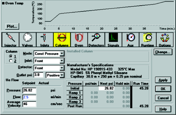
Column outlet pressure
The 6890 GC needs to know the pressure at the end of the column to be able to
calculate column flows. Use either the GC keyboard or the ChemStation to set
the outlet pressure for the column to 3.8 psig. The ChemStation screen where
the column outlet pressure is set is shown in Figure 14.
Inlet pressure
If this is a method used previously, you may want to reset the inlet pressure to
give similar retention times with the new column outlet pressure. Do this by
calculating the inlet pressure needed to keep the void (holdup) time the same
as the previous method. For constant inlet pressure methods, this will also
keep the elution order the same. The Method Translation Software tool or the
Flow Calculator tool can be used to do this calculation.
Figure 14 Column outlet pressure screen

Splitter Configurations 3
Installation and Operation Guide 35
Restrictor and Column Installation
Install the column
1Hang the analytical column on the column clips. The clips hold the outside
of the wire “basket” that supports the column. Adjust the clips if necessary.
2Connect the column to the inlet fitting.
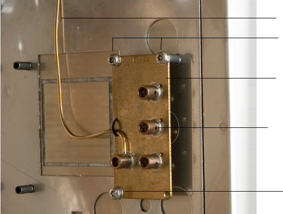
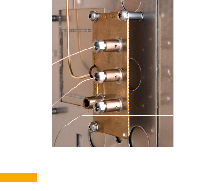
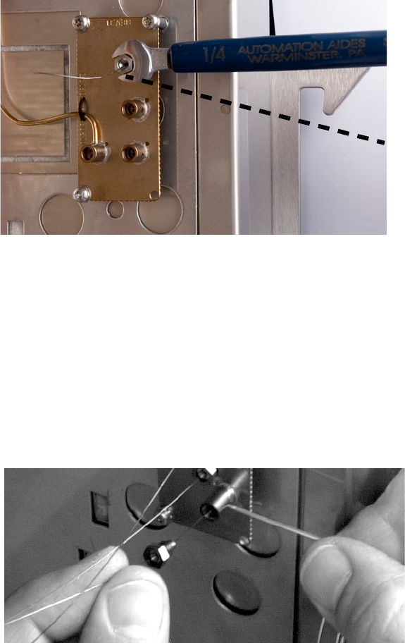
Connect the splitter
1Connect the restrictors to the connectors on the splitter (Figure 15).
Finger-tighten until just snug, then tighten with a wrench an additional 15°
(Figure 16). Install the back restrictor first.
2Connect the restrictors to the appropriate detectors.
3Connect the column exit to the splitter. Tighten as you did the restrictors.
NOTE Restrictors and the column exit are connected to the splitter assembly using internal nuts
and SilTite ferrules. See “Swaging SilTite Ferrules” on the CD for details.
CAUTION Arrange the tubing (restrictors and column) so that it does not touch the oven walls.
This could create a cold spot.
36 Installation and Operation Guide
3Splitter Configurations
Figure 15 Restrictor and column connections
Column exit
Restrictor 1
to Detector 1
Restrictor 2
to Detector 2
To ma keup
gas supply
CAUTION Do not overtighten the fittings. The dashed line in Figure 16 (about 15° clockwise from
finger-tight) is usually enough.
Splitter Configurations 3
Installation and Operation Guide 37
Disconnect tubing from the splitter
Loosen and remove the internal nut from the splitter fitting. Usually the
tubing and ferrule will fall out of the fitting.
Occasionally the ferrule will stick in the fitting. If this happens, use a pointed
object like a pen or a paper clip and insert it in the ferrule release hole in the
side of the fitting (Figure 17). Press firmly. The ferrule will click when it
breaks free.
Figure 16 Tightening the connections
15°
Figure 17 Releasing a ferrule
38 Installation and Operation Guide
3Splitter Configurations
Protect the column and restrictors
Column and restrictor tubes with swaged metal ferrules can be disconnected
and reconnected several times. To protect the tubing end, use one of the
brass-sealing caps from the kit. Tighten to finger-tight plus 15 degrees.
Protect the splitter
Seal the ports of the splitter assembly with plugs when the splitter is not
connected. This keeps particulates and contamination out. To make a plug, cut
about 2 inches of the stainless steel wire and swage it as you would a column.
Use the metal ferrule that fits 0.25-mm id columns. After swaging, clip the
wire to within 0.5 mm of the ferrule end with a small high-quality wire cutter.
Leave the excess wire on the other end to serve as a handle when removing the
plug.

39
Agilent G3180B Splitter Kit
Installation and Operation Guide
Agilent Technologies
4
Operation
An Example 40
Column flow 40
Select restrictors 42
Calculate column flow 43
Calculate ECD restrictor flow 44
Calculate MSD restrictor flow 45
Changing Columns Without Venting the MSD 46
Backflushing the Column 47
This chapter contains a worked-through custom configuration, plus some
special topics.
40 Installation and Operation Guide
4Operation
An Example
Assume we have a method that uses an HP-5MS column (30 m × 250 µm
id × 0.25-µm film thickness) to measure pesticides with an MSD. The initial
oven temperature is 70 °C and is programmed to 280 οC. The method is run in
constant pressure mode at 19.44 psig inlet pressure and the carrier gas is
helium. The initial column flow listed by the ChemStation is 2.1 mL/min.
We want to create a new splitter method with the column effluent split 1:3
between the ECD (detector 1) and an MSD (detector 2). We would also like to
preserve the retention times and relative elution order in the new method.
Column flow
Since the column outlet pressure will be much higher in the new method, the
first step is to calculate the new inlet pressure and the resulting column flow.
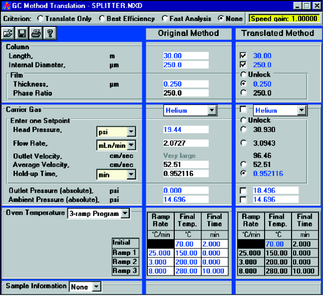
The Method Translation software (Figure 18) is useful for this. Use the None
mode and check the button to make the hold-up times the same.
Operation 4
Installation and Operation Guide 41
The outlet pressure entered for the new splitter method must be in absolute
pressure units. Since the outlet of the column will be 3.8 psig, we need to
convert this to psia for the method translator. Absolute pressure = gauge
pressure + 14.696. Hence, 3.8 + 14.696 = 18.496 will be entered.
The calculated inlet pressure for the new splitter method is 30.93 psig and the
new column flow is 3.09 mL/min.
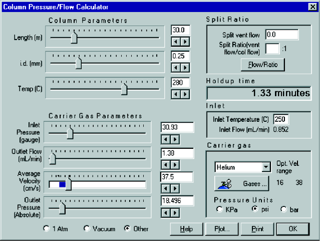
Figure 18 Calculating column flow
42 Installation and Operation Guide
4Operation
Select restrictors
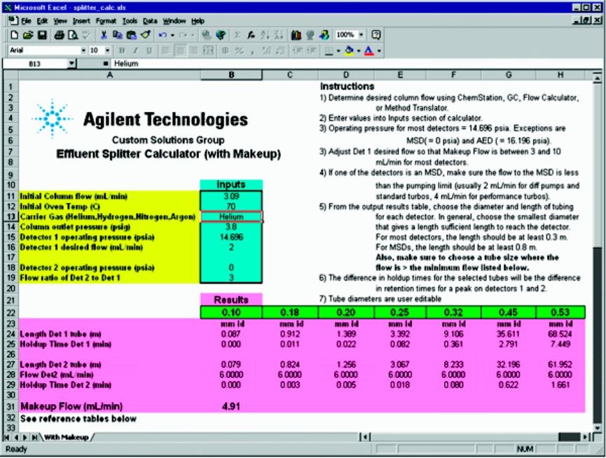
Start up the spreadsheet "splitter_calc.xls" in Excel. We will choose to have
2 mL/min go to the ECD initially. With a split ratio of 3, this will send
6 mL/min to the MSD. This flow is acceptable with a performance turbo
system but will give somewhat degraded detection limits. Fill in the input
column as shown (Figure 19) with the ECD assumed to be Detector 1 and the
MSD as Detector 2.
Figure 19 The Effluent Splitter calculator
Operation 4
Installation and Operation Guide 43
The calculator lists the lengths required for the different sizes of uncoated,
deactivated, fused-silica, restrictor tubing available. Choose the id tubing that
gives the shortest length of at least 0.3 m for most detectors and 0.8 m for
MSDs. In this case 0.18-mm id is the choice, requiring 0.912 m for the ECD
restrictor and 0.824 m for the MSD restrictor.
Table 4 on page 33 shows that in both cases the flow is higher than the
minimum 0.72 mL/min suggested for helium in 0.18-mm id tubing.
Calculate column flow
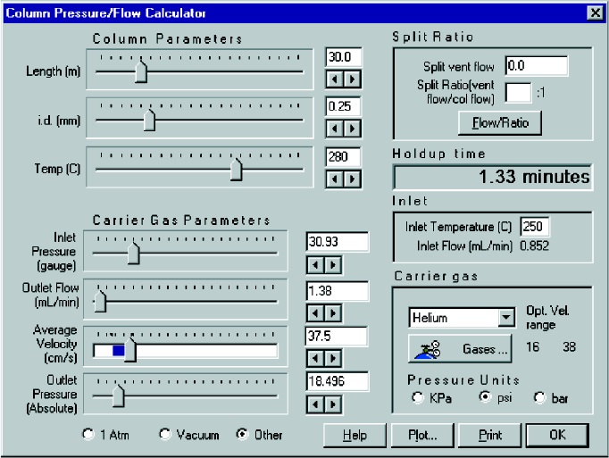
To find the makeup flow at 280 °C, first find the column flow at 280 °C. The
Flow Calculator software (Figure 20) requires that the output pressure be
entered in psia. Therefore 18.496 psia (3.8 psig) is entered.
The column flow drops to 1.38 mL/min at 280 °C.
Figure 20 Column flow calculation

Operation 4
Installation and Operation Guide 45
Calculate MSD restrictor flow
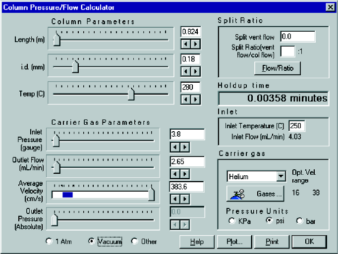
The flow through the MSD restrictor (Figure 22) at 280 °C is:
The flow to the MSD at 280 °C is 2.65 mL/min. This flow is higher than the
minimum 0.72 mL/min suggested for helium in 0.18-mm id tubing. The
calculated makeup flow is then [0.88 + 2.65] – 1.38 = 2.15 mL/min. This should
work well.
The configuration can now be installed and used.
Figure 22 MSD restrictor flow calculation
46 Installation and Operation Guide
4Operation
Changing Columns Without Venting the MSD
For systems that use an MSD attached to the splitter, one added advantage is
the GC column can be changed without venting the MSD. When the column is
disconnected from the splitter plate, the makeup gas purges air out of the
fitting, preventing air from reaching the MSD.
To change columns with the splitter, the recommended steps are:
1Cool down the inlet to which the column to be removed is connected.
2Disconnect the column from the splitter plate.
3Immediately install a plug in the plate where the column was connected.
4Change column in the inlet and turn on carrier gas to purge air from the
column.
5Preswage metal ferrule on the outlet end of the column.
6Remove plug from the connector.
7Connect the new column to the splitter.
Operation 4
Installation and Operation Guide 47
Backflushing the Column
One useful feature available with EPC control of the makeup is the ability to
backflush unwanted higher boiling analytes from the column. Use of this
feature requires that the split/splitless inlet be used. Backflushing reduces the
hold at the end of the run to clean out the column.
To backflush, the splitter makeup pressure is time-programmed to rise rapidly
after elution of the last peak of interest while the inlet pressure decreases
rapidly. These pressure changes reverse the flow through the column. Heavy
materials are then carried out the split vent of the inlet.
The inlet pressure is programmed to decrease to 0.5 psig. The makeup
pressure is programmed to rise to a maximum pressure determined by the
detectors and cleanout temperature used. Using the example from above, the
MSD will limit the flow, and thus pressure, that can be used for backflushing.
The flow allowed to go to the MSD (with a performance turbo) must be
8 mL/min or less. The backflushing conditions must be calculated to not
exceed this. We need to use the MSD restrictor tubing dimensions and the
backflushing temperature to find the backflushing pressure.
48 Installation and Operation Guide
4Operation
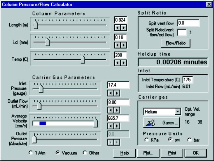
The restrictor to the MSD was 0.824 m of 0.18-mm id tubing. The backflushing
temperature used here is the hold temperature at the end of the run in the
original method (280 °C). The flow calculator (Figure 23) shows that the
makeup pressure can be programmed to 17.4 psig at 280 °C.
The time required for complete backflushing of heavy materials is then
determined empirically. Blank runs after samples with different backflush
hold times are used to determine the minimum time to remove all heavy
material.
Figure 23 Column backflush flow calculation
Installation and Operation Guide 49
Index
A
Absolute pressure, 41
Aux EPC, 27
Auxiliary Pressure controller, 24
B
Backflushing, 47
C
Changing columns, 46
Column
connections, 35
flow, 10, 26, 27, 43
outlet pressure, 34
Column clips, 35
Column effluent, 27
Configuration, 9
custom, 25, 29
typical, 25, 26
Constant flow mode, 27
Constant pressure mode, 28
Constant pressure operation, 10
Custom configuration, 29
Example, 40
D
Detector
Above atmospheric pressure, 9
Atmospheric pressure, 9
Below atmospheric pressure, 9
flow rate, 26
operating pressure, 26
Diffusion pump, 26, 28
E
Effluent Splitter Calculator, 29, 32, 42
Electronic pneumatic control, 10
Excel, 12
F
Ferrule
release hole, 37
Flow
column, 10, 26, 27
detector, 26
makeup, 10
maximum and minimum, 33
Flow Calculator, 34
Fused silica tubing, 27
G
GC Method Translation, 30
GC requirements, 12
I
Inlet pressure, 28, 34, 47
M
Makeup flow, 33
Makeup pressure, 47
Makeup supply, 24, 27
Metal ferrules, 10
Method Translation, 34, 40
Microfluidic plate, 10
MSD, 10, 28, 33, 40, 45, 46
O
Outlet pressure, 41
P
Parameter calculation, 11
Parts supplied, 13
PCM, 12, 27
Peak broadening, 26, 28
Plugs, 38
Pneumatic Control Module, 12
Pressure controller, 12
psia, 41
psig, 41
R
Restrictor, 8, 27
dimensions, 26
flow, 44, 45
Retention times, 34
S
Software tools
Column Pressure/Flow Calculator, 31
Effluent Splitter Calculator, 29
GC Method Translation, 30
loading, 31
Split ratio, 9, 26, 28, 29
Splitter connections, 35
Spreadsheet calculator, 9
T
Tailing, 28
Turbo pu mp, 26, 28
Installation and Operation Guide 50

Agilent Technologies
© Agilent Technologies, Inc.
Printed in USA, April 2006
G3180-90120
